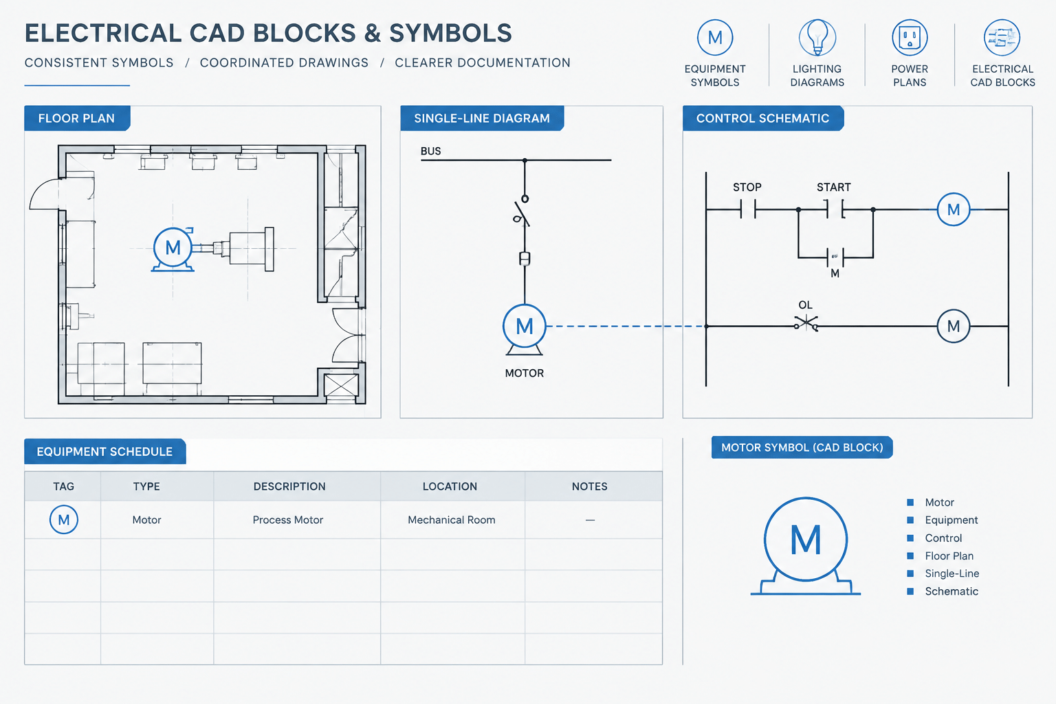
Motor control documentation in CAD depends on more than selecting the correct symbol. The equipment identity, source, controller, field devices, control functions, and supporting references must remain consistent wherever they appear.
The following guidance focuses on the drafting structure behind that coordination. It explains how plans, single-line diagrams, control schematics, schedules, details, block attributes, and review workflows can work together without forcing every type of information onto the same sheet.
Motor control documentation rarely fits on a single drawing. A motor may appear as an equipment connection on a floor plan, as a load on a single-line diagram, and as part of a sequence on a control schematic. It may also be referenced by a panel schedule, equipment connection schedule, mechanical drawing, or control narrative.
The drafting challenge is not simply placing a motor symbol. It is maintaining one coordinated identity and a clear design intent across every drawing where that motor appears. This guide explains how to organize motor control documentation in CAD while keeping plans, diagrams, schedules, and details consistent.
What Motor Control Documentation Communicates
A complete drawing package may need to answer several different questions about the same motor-driven equipment:
- Where is the equipment located?
- What electrical source serves it?
- What type of control arrangement is intended?
- Which devices are located near the equipment?
- Which functions are provided by electrical, mechanical, or controls disciplines?
- Where can the reader find connection data, control logic, or installation details?
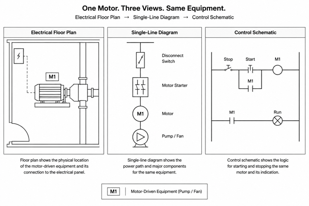
No single drawing type answers all of these questions well. The floor plan emphasizes location and routing. The single-line diagram emphasizes distribution. The control schematic explains logical relationships. Schedules organize repeatable data. Good documentation assigns each type of information to the drawing best suited to communicate it.
Establish One Equipment Identity
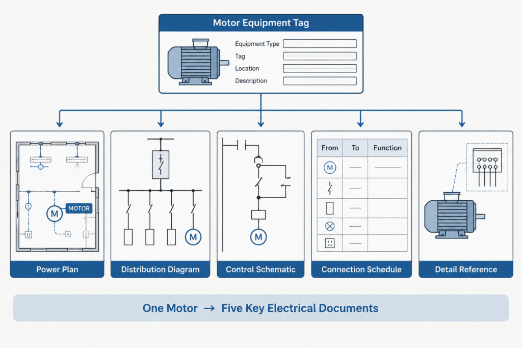
Start with a stable equipment tag that can be used across disciplines and drawing types. The tag should represent the motor-driven equipment or the motor according to the project’s established naming convention. Avoid creating separate, unrelated identifiers on the plan, diagram, and schedule unless the documentation system intentionally distinguishes them.
For example, a mechanical equipment tag might identify a fan, pump, or air-handling component. The electrical drawings can use that same tag as the primary coordination reference while adding an electrical device tag where necessary. If a controller or disconnect has its own identifier, the relationship between those tags should be visible in a schedule, note, or diagram.
Useful CAD block attributes
A motor or equipment-connection block can include attributes such as:
- Equipment tag
- Serving source
- Circuit or feeder reference
- Controller reference
- Disconnect reference
- Schedule key
- Drawing or detail reference
- Remarks
Not every value needs to be displayed beside the symbol. Some attributes may support extraction or quality control while remaining hidden in the plotted drawing. Keep visible annotations limited to information that helps the reader understand or navigate the documents.
Show Location and Relationships on the Plan
The electrical floor plan should show where the motor-driven equipment and associated field devices are located. Depending on the project scope, these devices may include a disconnect, controller, local control station, sensor interface, or connection point.
Place symbols relative to the coordinated architectural or mechanical background, but do not let a diagrammatic symbol imply a verified mounting location. If exact placement depends on manufacturer information, access clearances, or another discipline’s layout, communicate that dependency with an appropriate note or coordination reference.
Use circuiting lines, leader notes, or connection callouts consistently. A plan should make the association between the motor and its serving devices understandable without tracing several overlapping lines through a congested area. Where the arrangement is complex, use an enlarged plan or a referenced detail rather than compressing excessive information into the main floor plan.
Avoid treating the plan as a control schematic
A common drafting problem is trying to show the complete control sequence on the floor plan. This creates crowded leaders and ambiguous crossing lines. The plan should normally communicate physical or diagrammatic location, source association, and document references. Detailed control logic belongs in a schematic, point list, sequence, or dedicated control diagram.
Represent Distribution on the Single-Line Diagram
The single-line diagram shows how power reaches the motor load through the distribution system. It may depict the upstream source, protective device, feeder, controller, disconnecting device, and motor using a simplified path.
Symbols on a single-line diagram are functional rather than spatial. Their position on the sheet does not indicate field distance or physical orientation. Keep the diagram focused on electrical relationships and avoid importing plan geometry into it.
Each motor branch shown on the single-line diagram should be traceable to the corresponding equipment tag and plan location. If several similar loads are grouped diagrammatically, provide enough labeling to prevent the group from becoming an anonymous collection of motor symbols.
| Document | Primary purpose | Typical motor information |
|---|---|---|
| Floor plan | Location and coordination | Equipment tag, nearby devices, source reference, routing intent |
| Single-line diagram | Power distribution relationship | Source path, controller relationship, feeder identification |
| Control schematic | Functional logic | Commands, status, permissives, interlocks, control relationships |
| Equipment connection schedule | Organized connection data | Tag, source, connection method, control notes, remarks |
| Detail or elevation | Arrangement clarification | Device grouping, interfaces, mounting concept, references |
Use Schematics to Explain Control Intent
A control schematic should explain how commands and conditions relate, not reproduce the physical route of every conductor. Arrange the graphic so a reviewer can follow the intended sequence in a predictable direction.
Control functions may include start and stop commands, remote enable signals, status indication, alarms, permissives, and interlocks. The drawing should make clear which functions are hardwired, which are communicated through a control system, and which are only referenced to another discipline’s documents. Do not draw a continuous hardwired connection when the design intent is actually a networked or software-based interface.
Separate functional and physical information
Physical terminal assignments, conductor identification, and manufacturer-specific wiring may not be available during early design. Avoid inventing those details. A design schematic can document functional intent and interface responsibility while reserving final point-to-point information for verified submittals or later documentation.
Use consistent line conventions for power, control, and communications relationships. Define those conventions in the drawing legend rather than assuming every reader will interpret them the same way.
Coordinate Controllers and Disconnects Carefully
Terms such as starter, controller, variable-frequency drive, combination unit, and disconnect describe different functions or equipment arrangements. A generic block should not be used in a way that falsely implies a specific construction.
Before selecting a symbol, determine what the drawing actually needs to communicate:
- Is the symbol identifying a functional controller or a particular equipment assembly?
- Is a disconnect shown as separate from or integral to another device?
- Does the plan show a physical device while the single-line diagram shows its electrical function?
- Is the controller furnished under the electrical scope, another discipline, or an equipment package?
- Does the control schematic need to distinguish local and remote commands?
If these answers are not settled, use neutral terminology and clearly marked coordination notes instead of selecting an overly specific symbol.
Build a Cross-Drawing Coordination Matrix
For projects with many motor loads, a simple coordination matrix can help the CAD team find omissions and conflicting references. Each row represents an equipment tag, while columns record where the item appears.
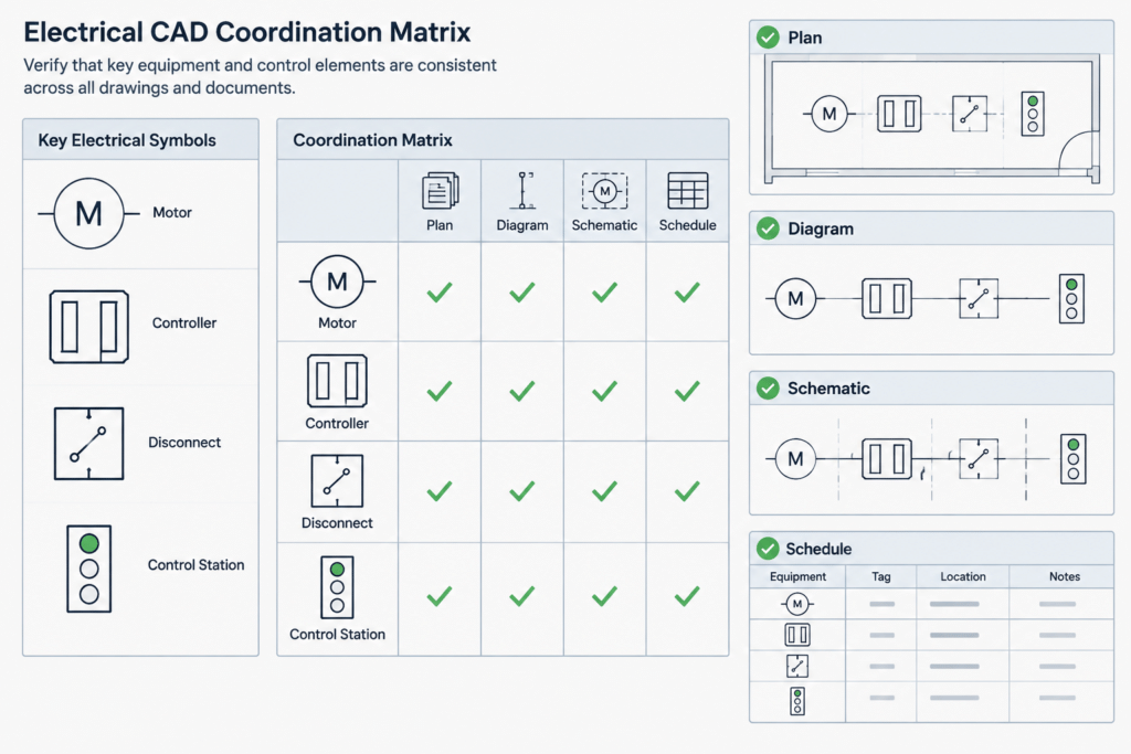
- Plan sheet and location
- Single-line diagram reference
- Panel or distribution source
- Connection schedule entry
- Control schematic reference
- Detail reference
- Mechanical schedule match
- Open coordination comment
The matrix can exist in a worksheet, database, or CAD table workflow. It does not have to become a contract drawing. Its value is in checking that each motor has a complete and consistent documentation path.
Organize CAD Layers and Blocks by Purpose
Keep motor equipment symbols, circuiting, control relationships, tags, and reference annotations separable. This makes it easier to control plot hierarchy and display information differently on power plans, control plans, and coordination backgrounds.
Blocks should have a consistent insertion point and a predictable text arrangement. Create separate plan and diagram representations when their graphic needs differ, but connect them through shared tag values or data-management procedures. Stretching or rotating one block into every possible use often produces inconsistent text and misleading graphics.
Include a revision note or library status for office-standard blocks. A symbol copied from an older project may carry obsolete layer assignments, unexplained attributes, or project-specific assumptions.
Perform a Motor Documentation Review
Before issuing the drawings, review motor-related information as a coordinated set rather than checking each sheet in isolation.
- Confirm that equipment tags match the latest coordinated background and schedules.
- Verify that every plan connection has an identifiable serving source.
- Compare single-line labels with plan and schedule references.
- Check that controller and disconnect symbols describe the intended functions without unsupported specificity.
- Verify that control lines are distinguished from power and communications relationships.
- Look for duplicate tags, orphaned symbols, and references to removed details.
- Confirm that notes assigning scope or responsibility are consistent across sheets.
- Flag unresolved ratings, wiring details, and equipment configurations for design verification rather than guessing.
Keep the Documentation Traceable
Clear motor control documentation is built around traceability. A reader should be able to begin with a motor symbol on a plan, identify its source, find its distribution path, understand its control intent, and locate any supporting schedule or detail.
CAD blocks support that process, but the blocks are only part of the system. Stable tags, disciplined cross-references, appropriate drawing types, and coordinated revisions are what turn separate symbols into a useful technical record. All final equipment selections, ratings, connection requirements, and project-specific details should be verified by the responsible design team before the drawings are used for construction.
Managing Changes Across the Drawing Set
Motor documentation should be reviewed whenever an equipment tag, serving source, controller arrangement, device location, or control responsibility changes. A revision that appears minor on one sheet may affect several related documents.
Use the equipment tag as the primary search key during revision review. Check every plan symbol, diagram branch, schematic reference, schedule row, detail callout, and coordination note associated with that identity. This reduces the risk of leaving an outdated source reference or control description elsewhere in the set.
Distinguish design intent from pending information
CAD annotations should make a clear distinction between confirmed design information and unresolved coordination items. Do not fill incomplete attributes with assumed equipment characteristics or manufacturer-specific connections. Instead, record the open issue in the project’s coordination process and keep the published drawing terminology appropriately neutral.
Check deliverables as connected records
A useful final review follows the documentation path from the plan to the source diagram, schedule, schematic, and supporting detail. The reverse check is also valuable: every scheduled or diagrammed motor load should lead back to an identifiable plan location or a clearly explained exception.
This approach treats CAD entities as connected records rather than isolated graphics. It also makes later revisions easier because the drafting team can identify which references must change when equipment information is updated.
Motor Control CAD Documentation FAQ
Should the same motor symbol be used on every drawing?
Not necessarily. A plan symbol communicates location, while a single-line symbol communicates a distribution relationship and a schematic symbol communicates function. The graphics may differ, but their equipment tags and cross-references should remain coordinated.
What information should remain visible beside a plan symbol?
Show information that helps readers identify the equipment, understand its source association, or locate related documentation. Data used only for extraction or checking can remain in hidden block attributes when supported by the office workflow.
How should unresolved controller information be documented?
Use neutral functional language and a clear coordination note. Avoid showing a specific assembly, internal wiring arrangement, or device configuration until that information has been verified by the responsible design team.
Why should power, control, and communications lines be separated?
Distinct line conventions help readers understand the type of relationship being shown. They also prevent a communications interface from being mistaken for a hardwired control connection or a power path.
Can a coordination matrix replace the drawing schedules?
A coordination matrix is primarily a quality-control tool. It can track where equipment appears and expose missing references, but it does not automatically replace schedules or other documents required by the drawing package.
What should be checked after a motor tag changes?
Review the plan, single-line diagram, control schematic, connection schedule, details, notes, and references from other disciplines. Also check hidden block data and extracted records that may retain the previous identity.




Leave a Reply
You must be logged in to post a comment.