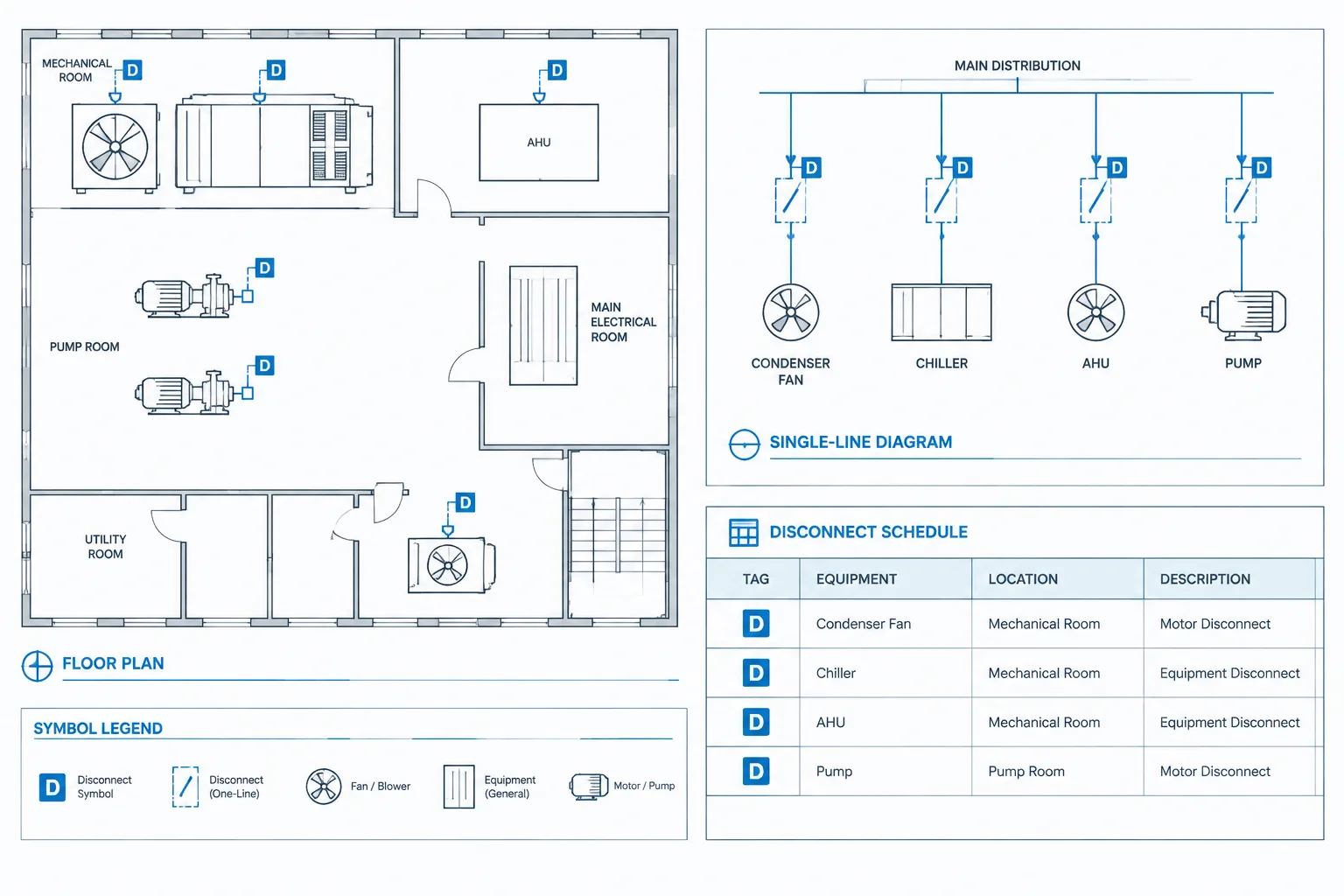
Electrical disconnect documentation in CAD depends on more than placing a symbol near the equipment it serves. The same device may also appear in a one-line diagram, equipment schedule, control schematic, detail, or coordination view. Each representation has a different purpose, but all should retain a consistent device identity.
This reference explains how to connect those representations without treating a generic CAD block as a complete product specification. It focuses on tagging, drawing relationships, schedule structure, attributes, layers, revision control, and quality review.
Electrical disconnects often appear simple on a floor plan, but their documentation can touch several parts of an electrical drawing set. A disconnect may need a plan symbol, equipment tag, circuit or feeder reference, single-line representation, schedule entry, mounting note, and coordination information for connected equipment.
When these references are developed independently, discrepancies are easy to introduce. A plan may show a disconnect that is missing from the single-line diagram, or a schedule may describe a different device type from the one indicated elsewhere. A coordinated CAD workflow treats each disconnect as one documented device with multiple drawing representations.
What a disconnect symbol communicates
On an electrical plan, a disconnect symbol primarily identifies location and design intent. It does not usually communicate every characteristic of the device. The surrounding tags, schedules, diagrams, and notes provide the remaining information.
Depending on project conventions, disconnect documentation may identify:
- A unique equipment tag or device identifier
- The equipment served
- The source panel, switchboard, motor control assembly, or other upstream equipment
- A circuit or feeder reference
- Whether the device is fused or non-fused
- Whether the disconnect is separate from or integral to the connected equipment
- An enclosure or environmental classification when required by the design
- A reference to a schedule, detail, elevation, or control diagram
The symbol should remain readable at the intended plot scale. Dense technical descriptions placed beside every symbol can overwhelm the plan. A short tag linked to a controlled schedule is often clearer than repeating the full device description throughout the drawing.
Choose a consistent plan representation
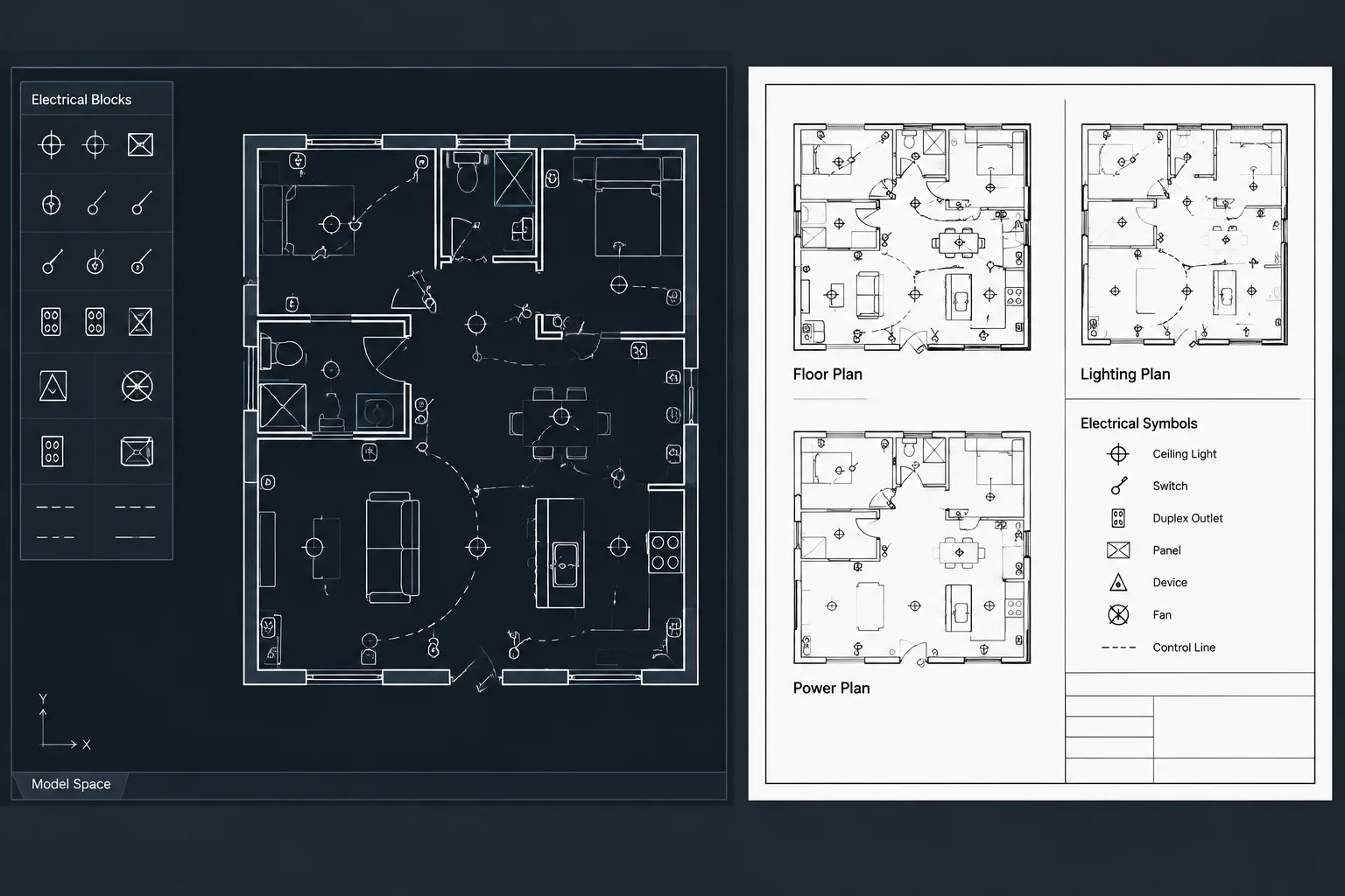
A CAD library may contain several disconnect symbols, including wall-mounted devices, safety switches, local isolating devices, combination units, and diagrammatic switch symbols. These blocks should not be used interchangeably without checking their intended context.
Plan-view symbols
A plan-view symbol indicates approximate placement and helps coordinate the device with walls, equipment, doors, piping, and access areas. It may be diagrammatic rather than a literal outline of the enclosure. If physical size affects coordination, use a verified equipment footprint or a clearly labeled placeholder instead of assuming that the generic symbol represents actual dimensions.
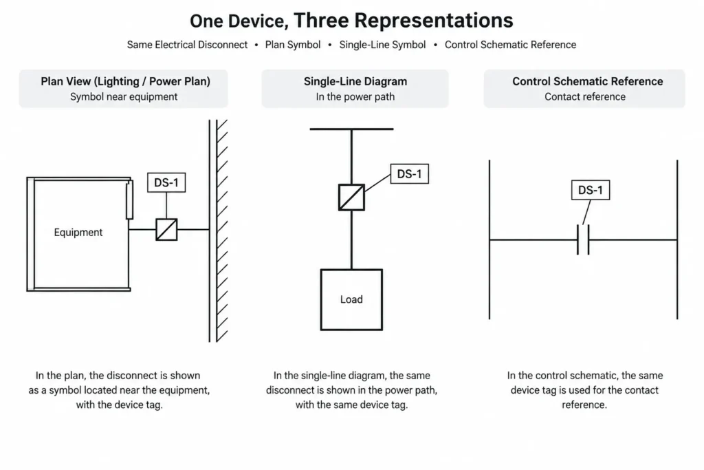
Single-line symbols
A single-line symbol describes the disconnect’s position in the power path. It is normally selected for diagram clarity rather than physical appearance. Additional notation may distinguish device functions, but the drawing legend must explain any project-specific graphics or abbreviations.
Schematic and control symbols
Control diagrams may show auxiliary contacts, interlocks, control power, or status points associated with a disconnect. These symbols communicate functional relationships and should not be mistaken for plan locations. Cross-references can connect control functions to the physical device tag.
Create a stable tagging method
Every separately documented disconnect should have a stable identifier. The tag allows reviewers to follow the same device across plans, diagrams, schedules, details, and revisions.
A useful tag system should be:
- Unique within the drawing set
- Short enough to remain legible on plans
- Independent of temporary CAD selection order
- Compatible with equipment schedules and database exports
- Stable when a device moves to another location
Avoid relying only on nearby equipment text, such as labeling a symbol with the name of the served unit. Similar equipment may occur in several locations, and equipment names may change during coordination. A unique disconnect tag can remain constant while its description and references are updated.
If block attributes are used, separate the device identifier from source, load, type, and notes. Combining all information into one text attribute makes filtering, schedule creation, and revision checking more difficult.
Coordinate the plan and single-line diagram
The floor plan answers where the disconnect is located. The single-line diagram answers where it sits electrically. Both views should refer to the same device without forcing the reader to infer the connection.
| Documentation item | Plan emphasis | Single-line emphasis |
|---|---|---|
| Device tag | Identifies the physical symbol | Connects the electrical representation to the same device |
| Source | May appear as a circuit, feeder, or home-run reference | Shown through the upstream connection |
| Served load | Shown by proximity, a connection line, or equipment tag | Shown as the downstream load or continuation |
| Device function | Communicated by symbol, abbreviation, or schedule reference | Communicated by the diagram symbol and notation |
| Physical location | Coordinated against the building background | Usually not represented geographically |
When a disconnect appears on only one drawing type, confirm whether that is intentional. Some local devices may be omitted from a simplified distribution diagram, while major distribution disconnects may appear on a diagram and an equipment-room plan. The project documentation rules should define the expected level of representation.
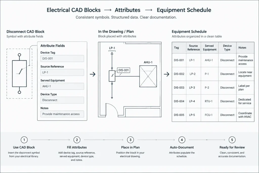
Build a disconnect schedule around coordination needs
A disconnect schedule can centralize data that would otherwise be repeated across the drawing set. The schedule structure should reflect the project’s documentation needs rather than copying every possible product field.
Common schedule fields include:
- Disconnect tag
- Location or area
- Served equipment tag
- Source equipment reference
- Device description
- Fused or non-fused designation, where applicable
- Drawing or detail reference
- Mounting or coordination note
- Remarks
Technical ratings and enclosure requirements must come from verified design information. Do not infer them from a generic CAD block, a previous project, or the apparent size of connected equipment. If information is unresolved, use an agreed placeholder status that is easy to find during quality control.
Show the relationship to connected equipment
A plan should make it clear which equipment a local disconnect serves. Proximity alone may be ambiguous in crowded mechanical rooms, rooftops, production areas, or service spaces.
Possible documentation methods include a short connection line, matching equipment references, coordinated keynotes, or an equipment connection schedule. Whichever method is selected, use it consistently. Avoid long connection lines that cross unrelated devices or resemble branch-circuit routing.
Also distinguish between a separate disconnect and one that is part of another assembly. Showing an additional standalone symbol for an integral device can imply duplicate equipment. Conversely, failing to identify a separate device may leave its location and scope unclear.
Coordinate access and mounting information
The plan symbol should be checked against architectural and equipment backgrounds. Review wall orientation, door swings, equipment service zones, piping, ducts, structural elements, and other electrical enclosures. If the device is mounted on or near served equipment, confirm that the host equipment location is current.
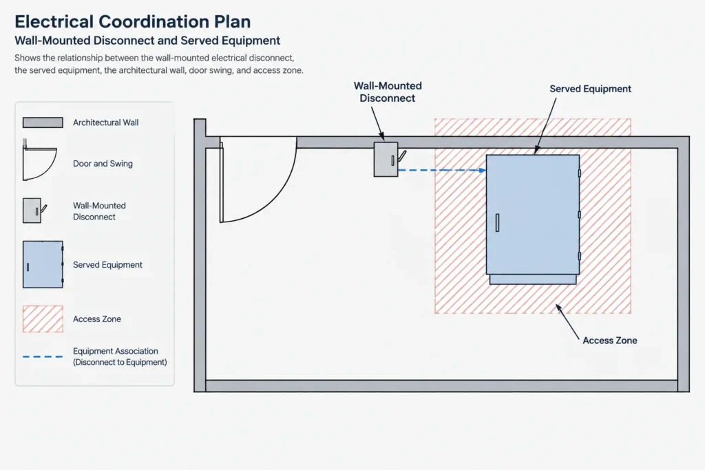
Do not treat a generic block boundary as a verified enclosure or access dimension. Where spatial coordination matters, show a separate, clearly classified zone based on validated project criteria. Keep these coordination graphics on controlled layers so they can be displayed on working drawings without necessarily appearing on every issued sheet.
Use layers and attributes deliberately
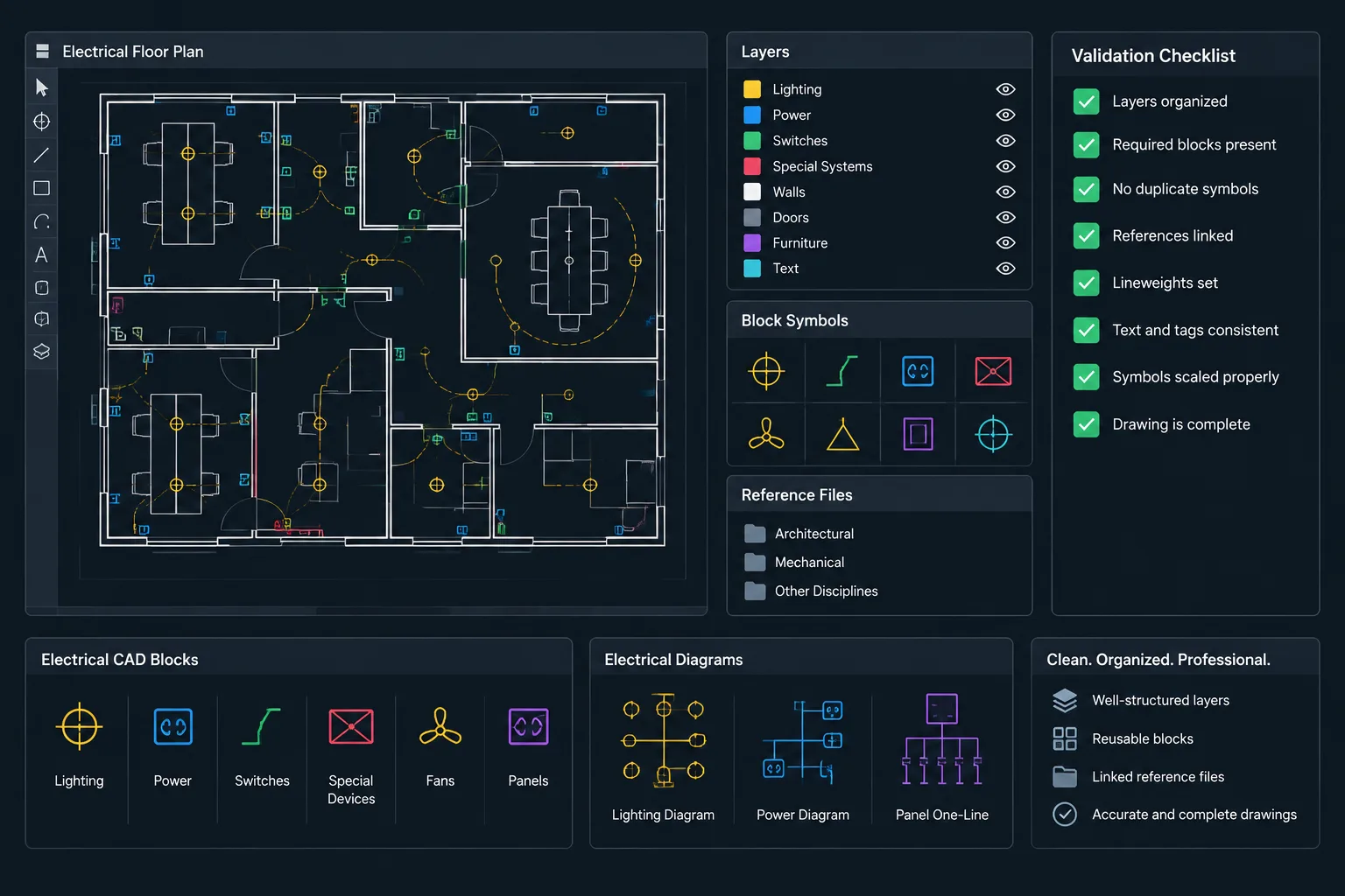
Disconnect blocks should follow the project’s layer, color, linetype, and plotting conventions. A practical block may contain separate components for the symbol, tag, descriptive text, and optional connection graphics. This allows the drawing team to control visibility without exploding the block.
Useful attribute fields can include the unique tag, served equipment, source reference, device classification, schedule status, and drawing note. Attribute names should be understandable to someone reviewing the file later. Hidden data should not become the only location of information needed to interpret the issued drawing.
Review disconnects as a coordinated device list
Quality control is more reliable when disconnects are reviewed as a complete population rather than one sheet at a time. An attribute export, schedule comparison, or drawing search can help locate missing and duplicated tags.
Before issue, check that:
- Every plan symbol has a unique and readable tag
- The served equipment is unambiguous
- Source references agree with the applicable diagram or schedule
- Fused and non-fused descriptions are consistent across drawings
- Separate and integral devices are clearly distinguished
- Single-line symbols and plan symbols refer to the same devices
- Deleted devices have been removed from schedules and diagrams
- Relocated devices retain correct references and coordination notes
- Generic blocks are not being used as verified equipment footprints
- Unresolved information is visibly tracked for later confirmation
Maintain one source of truth
The most effective workflow assigns each data field a primary location. The device tag and location may originate on the plan, while electrical relationships may be controlled by the single-line diagram and descriptive information by the schedule. Other drawings can then reference that information instead of recreating it independently.
Good electrical disconnect documentation is less about adding notes and more about building dependable relationships. When blocks, tags, schedules, and diagrams share a controlled identity, the drawing set becomes easier to review, revise, and use for coordination.
A practical reconciliation workflow
A coordinated review can begin with a device list generated from plan symbols or maintained in a controlled schedule. Compare that list with the one-line diagram, connected-equipment references, and any control drawings that identify the same disconnects. The objective is not to force every device onto every drawing, but to confirm that each required representation is present and uses the same identity.
Define where each field is controlled
Assign an authoritative location for the disconnect tag, source relationship, served equipment, device description, and coordination notes. Referenced drawings may display those fields, but independent copies can drift apart during revisions. Where the CAD platform supports linked data or attribute extraction, use it to reduce manual transcription while keeping issued drawings understandable without access to hidden data.
Separate identity from specification
The block name, graphic shape, and device tag serve different purposes. A block name helps manage the CAD library, the symbol communicates drawing intent, and the tag identifies the documented device. Product characteristics should come from verified design information rather than assumptions based on any of these items.
Record intentional omissions
Not every local disconnect must appear on a simplified distribution diagram, and not every diagram device requires a geographically precise plan symbol. Document the project rule governing those choices. This helps reviewers distinguish an intentional omission from a coordination error.
Review changes by device rather than by sheet
When equipment is added, removed, renamed, or relocated, search for its disconnect tag throughout the drawing set. Review the plan, one-line diagram, schedule, details, control references, and annotation together. This device-centered approach is more dependable than assuming that a revision made on one sheet has propagated everywhere else.
Common documentation conflicts to flag
- A disconnect tag appears more than once but refers to different served equipment.
- The plan and one-line diagram use different tags for the same apparent device.
- A schedule lists a separate disconnect while the equipment note describes an integral device.
- The source reference points to equipment that has been renamed or removed.
- A generic block is interpreted as a verified enclosure footprint.
- Unresolved device information is hidden in attributes and is not visible to drawing reviewers.
- A relocated symbol retains obsolete connection graphics, notes, or detail references.
These checks support drawing coordination only. Final device selection, ratings, installation requirements, and field conditions require review against verified project design information.
Frequently asked questions
Should the plan symbol match the physical appearance of the disconnect?
Not necessarily. A plan symbol may be diagrammatic and intended mainly to communicate location and device type. When actual enclosure geometry affects coordination, use a verified footprint or identify the geometry as a placeholder.
Should every disconnect shown on a plan also appear on the one-line diagram?
That depends on the drawing set’s representation rules. Simplified diagrams may omit some local devices, but the omission should be intentional and consistently applied. A documented device list can help reviewers identify missing references.
What is the purpose of a unique disconnect tag?
The tag connects the physical plan symbol to its electrical, schedule, detail, and control representations. It also helps the drawing team locate duplicates, omissions, and outdated references during revisions.
Can a CAD block determine whether a disconnect is fused or non-fused?
No. The graphic may represent a documented classification, but the required device characteristics must come from verified design information. Do not infer them from a generic block name or appearance.
What information belongs in block attributes?
Attributes can hold the device tag, served-equipment reference, source reference, classification, schedule status, and drawing notes. Keep fields separate so they can be filtered and checked, and do not hide information that readers need to interpret the issued drawing.
How should integral disconnects be documented?
Clearly associate the disconnect function with the equipment assembly and avoid adding a separate plan symbol that could imply another device. The plan, schedule, and diagram should use consistent wording and references.








Leave a Reply
You must be logged in to post a comment.