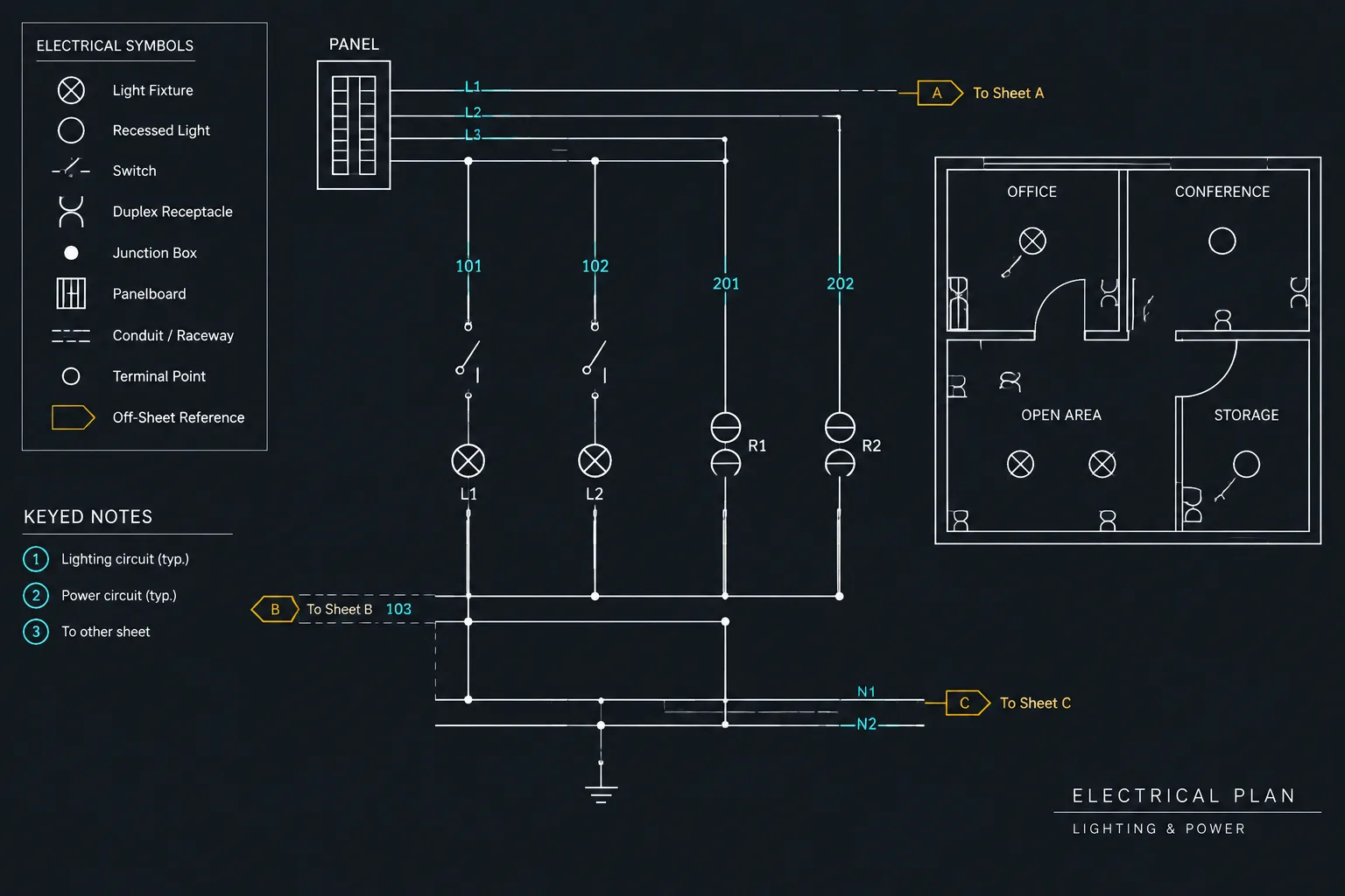
Wire numbering in electrical schematics works best when identifiers are treated as coordinated drawing data rather than isolated text labels. A clear workflow connects each conductor designation with its terminals, devices, continuation references, cable records, and related schedules.
This guide explains the drafting decisions behind a maintainable identification system. It focuses on CAD organization, drawing readability, cross-document coordination, and revision control without prescribing a universal numbering convention.
Wire numbers help readers follow electrical connections through schematics, terminal diagrams, panel drawings, and related documentation. Their value does not come from the numbering format alone. A useful wire identification system must remain consistent as conductors pass through devices, cross drawing boundaries, enter terminal strips, and appear in schedules.
In CAD, wire numbering is therefore both a graphic task and a data-management task. The drafter must decide where identifiers appear, what causes an identifier to change, and which drawing or schedule controls the information. The project design criteria, owner requirements, and applicable documentation standards should establish the final convention. The workflow below focuses on drawing clarity and coordination rather than prescribing a universal numbering method.
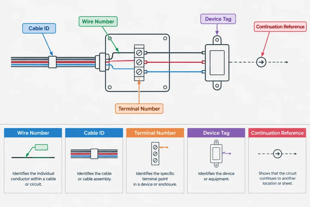
Wire Numbers, Cable IDs, and Terminal Numbers Are Different
Several identifiers can appear near the same connection, but they do not describe the same thing. Treating them as interchangeable is a common source of confusing schematics.
| Identifier | What it identifies | Typical documentation role |
|---|---|---|
| Wire number | An individual electrical connection or conductor | Supports tracing between connected points |
| Cable ID | A grouped cable assembly | Connects cable schedules, routes, and termination information |
| Conductor reference | A specific conductor within a cable | Distinguishes cores, pairs, or members of the same cable |
| Terminal number | A connection position on a terminal strip or device | Defines the physical or documented termination point |
| Device tag | A component, instrument, relay, or other device | Links symbols to schedules and related drawings |
| Connection reference | A continuation location elsewhere in the drawing set | Directs readers to another rung, sheet, zone, or diagram |
A single schematic connection may legitimately show several of these values. The graphic hierarchy should make clear which text is the wire number and which text belongs to the terminal, cable, or device.
Define What a Wire Number Represents
Before placing tags, document the project rule for electrical continuity. Some systems assign one identifier to an uninterrupted connection. Others change the identifier when the connection passes through a terminal, contact, connector, or device. Either approach can be documented clearly, but mixing the rules within one drawing set makes troubleshooting and review difficult.
The drafting convention should answer questions such as:
- Does a pass-through terminal preserve the same wire number?
- Does each side of a component receive a different identifier?
- How are spare conductors represented?
- How are cable members associated with the parent cable ID?
- What event causes a wire number to be retired or replaced?
- How are connections that leave the sheet continued?
Record these decisions in the project CAD manual, design criteria, schematic legend, or drawing notes as appropriate. Avoid relying on an unwritten office habit that outside reviewers cannot interpret.
Choose a Numbering Logic That Can Survive Revisions
A wire identification system may be sequential, location-based, drawing-derived, circuit-derived, or generated from project data. Each method has tradeoffs.
Sequential identifiers
Sequential numbering is straightforward and can remain independent of sheet layout. However, inserted connections may require new identifiers that do not appear in a visually neat order. Renumbering existing wires merely to restore the sequence can create unnecessary revision impacts.
Drawing-derived identifiers
An identifier based on a sheet, rung, grid, or drawing location can help readers find its source. Its weakness is sensitivity to document reorganization. Moving a rung or dividing a drawing may make the existing identifier look outdated, while renumbering it can affect terminal plans, reports, and field records.
Functional or circuit-based identifiers
Identifiers related to a system or function can communicate design intent, but they require a controlled naming structure. Similar abbreviations can become ambiguous, especially when several systems share a panel or enclosure.
The best project choice is not necessarily the shortest label. Prefer a convention that remains unique, readable, and stable when the design changes. For existing facilities, compatibility with the owner’s established identification system may be more important than introducing a new office preference.
Place Wire Numbers for Unambiguous Reading
A wire number should visually belong to one conductor line. Place it close enough to establish that relationship without covering junction dots, contact symbols, terminal markers, or crossing lines.
Use consistent offsets and text orientation throughout the drawing set. On dense schematics, a small text gap or break in the conductor line may improve readability, but it must not make the connection appear open. Background masks can help in selected situations, although excessive masking may hide nearby geometry.
When parallel conductors run close together, staggered tags may be easier to read than labels forced into one column. Leaders should be used cautiously because they can resemble conductor lines. If leaders are necessary, give them a distinct graphic treatment and keep their endpoints unmistakable.
Repeat identifiers where they add value
An identifier does not always need to appear along every visible segment of a continuous wire. It should appear often enough that a reader can trace the connection without guessing. Repeating it near terminals, connectors, off-sheet transitions, or crowded branches can improve usability.
Repeated labels must remain coordinated. If the same number is typed independently in several places, one revision can leave conflicting values. Attribute-based symbols, linked data, or controlled review reports may reduce this risk, depending on the CAD platform and project workflow.
Coordinate Branches, Junctions, and Crossings
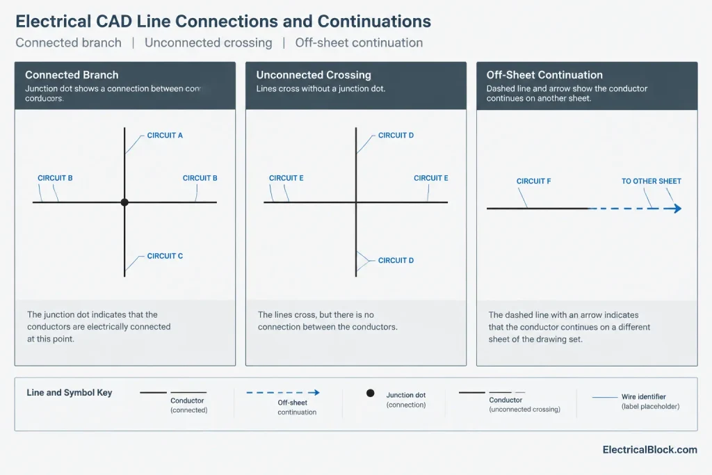
Wire numbering depends on a clear distinction between connected and unconnected linework. A branch with a junction is not the same as two lines that merely cross. Junction dots, line jumps, spacing, and drawing conventions should be applied consistently before wire identifiers are assigned.
For branched connections, the project rules should establish whether each branch retains the common identifier or receives a separate one. Do not use numbering to compensate for unclear junction graphics. The connection itself must be readable even before the labels are considered.
Handle Terminals and Connectors as Coordinated Data
At a terminal strip, readers may need to see the wire number, terminal number, terminal strip tag, destination, and cable information. Attempting to place all of this directly beside every symbol can overwhelm the diagram.
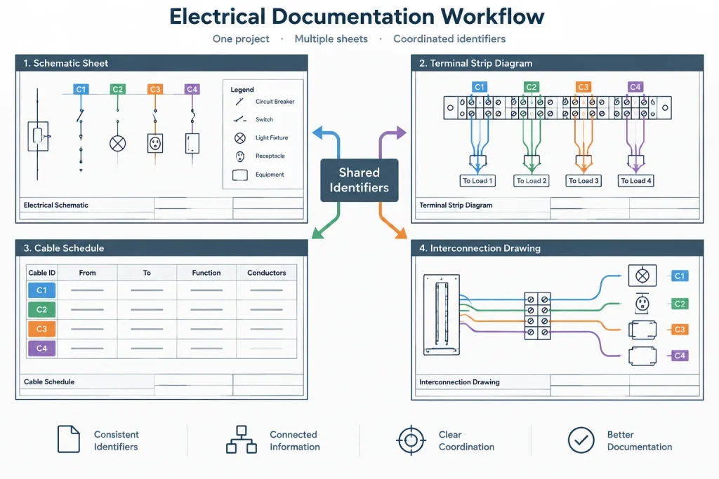
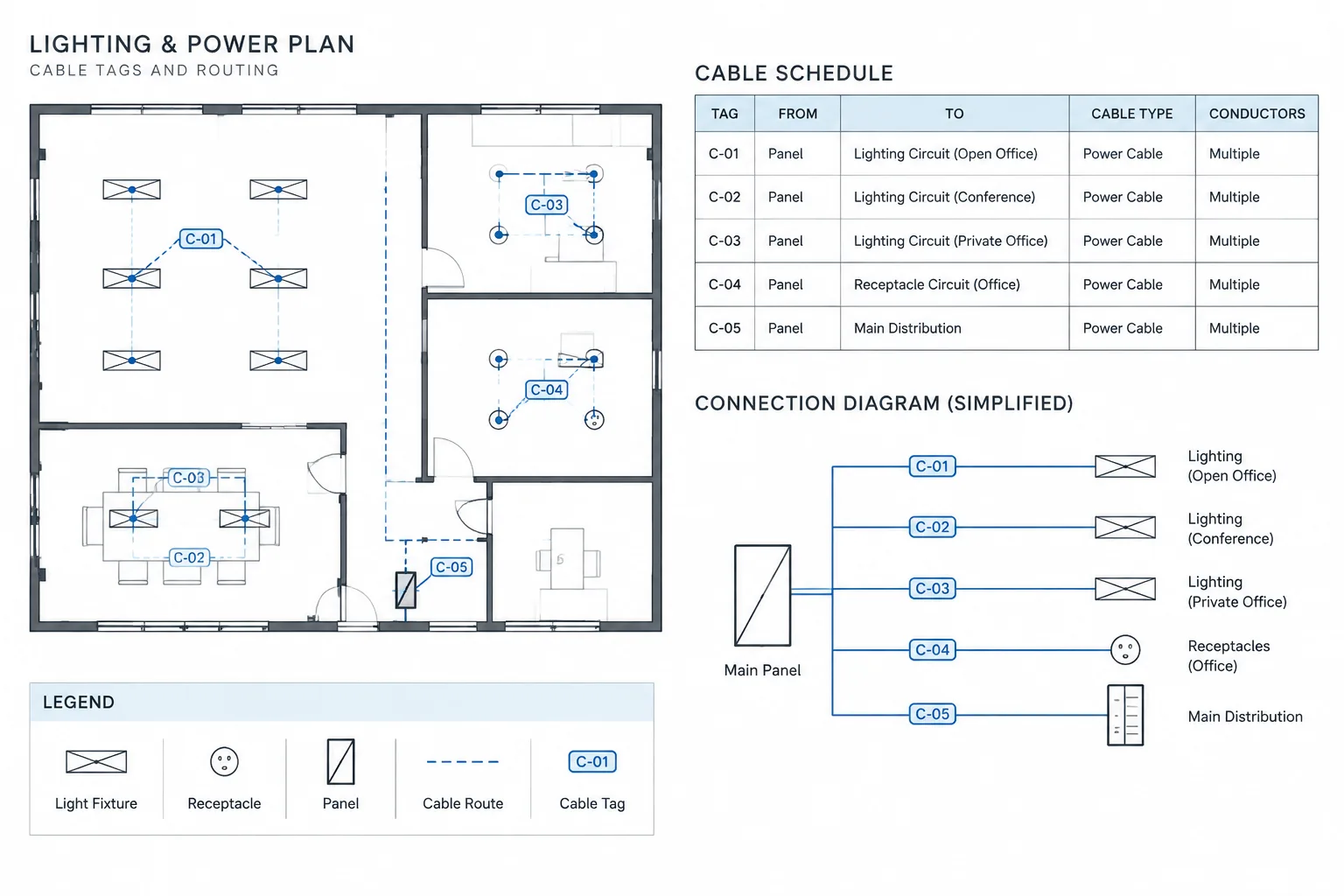
Divide the information among the schematic, terminal diagram, and schedule according to each document’s purpose. The schematic should explain electrical relationships. A terminal drawing can organize physical termination positions. A schedule can hold structured from-to, cable, conductor, destination, or remark fields.
Whatever division is selected, use stable keys between documents. A terminal strip tag and terminal number should point to one documented position. A cable ID should match the cable schedule. A wire number should not change merely because it appears in a different view.
Manage Off-Sheet Continuity
When a wire continues beyond the current sheet or diagram area, the continuation reference and wire identifier should work together. The identifier answers “which connection is this?” while the cross-reference answers “where does it continue?”
A continuation marker may refer to another sheet, drawing zone, rung, or destination device. Use the reference structure established for the project and verify both ends. A one-way reference or an obsolete destination can make an otherwise correct wire number difficult to use.
During review, trace each off-sheet connection in both directions. Confirm that the wire identity, source, destination, and continuation reference agree.
Build a CAD Layer and Object Strategy
Keep conductor geometry, wire-number text, terminal symbols, device graphics, and cross-references logically separated. This does not require a layer for every possible data type, but it should allow the drawing team to control visibility and plotting without selecting individual objects.
A practical structure should support:
- Consistent plotting of conductor lines and annotation
- Temporary isolation of wire numbers during review
- Filtering or extraction of tagged objects
- Protection against accidental movement of background geometry
- Clear distinction between live project data and reference graphics
Avoid exploding intelligent tags merely to adjust their appearance. Exploded text may look correct on one sheet while losing the data relationship needed for later updates or extraction.
Use a Controlled Revision Workflow
Wire-number changes can affect more than the edited schematic. Before revising an identifier, find every related occurrence in terminal drawings, interconnection diagrams, cable documentation, panel drawings, reports, and issued records.
Identify the design change. Determine whether electrical continuity changed or only the graphic layout moved.
Preserve stable IDs where practical. Do not renumber unaffected wires solely to make a sequence appear tidy.
Update coordinated documents. Revise every schedule, terminal, continuation, and connection reference that uses the identifier.
Run duplicate and orphan checks. Look for one number assigned to unrelated connections and for tags no longer attached to valid linework.
Compare against the previous issue. Confirm that changed identifiers are intentional and included in the documented revision scope.
Quality-Control Checklist
- Every wire identifier follows the project naming convention.
- Identifiers are unique wherever uniqueness is required.
- Text is visibly associated with the correct conductor.
- Junctions and crossings are clear without relying on labels.
- Both ends of off-sheet connections agree.
- Wire numbers match terminal and interconnection documentation.
- Cable IDs are not being used as substitutes for individual wire identifiers.
- Repeated occurrences of the same identifier are coordinated.
- Spare, abandoned, and future connections use defined project terminology.
- Revision checks include schedules and diagrams, not only the edited sheet.
Make the Identification System Part of the Drawing Language
Effective wire numbering in electrical schematics is not simply a matter of placing text beside lines. It is a documentation system connecting schematic logic, termination points, cables, devices, and drawing references.
Define the continuity rule first, select identifiers that can tolerate project changes, and give each type of tag a clear graphic role. When wire numbers are treated as coordinated project data rather than isolated annotations, the drawing set becomes easier to review, revise, and navigate.
A Practical Review Method for Wire Identification
A useful review begins with connectivity rather than typography. First confirm what the conductor line connects, where its electrical identity begins and ends, and whether junctions or continuation markers are unambiguous. Then verify that the displayed identifier follows the documented project rule.
Reviewers should also compare the schematic against related terminal, cable, interconnection, and panel documentation. A label can be graphically correct yet still conflict with a schedule or destination reference. These comparisons are especially important after device substitutions, terminal changes, drawing reorganization, or revisions to off-sheet connections.
Separate appearance checks from data checks
- Appearance review: Confirm that text orientation, placement, spacing, masking, and plotting make the identifier easy to associate with the correct conductor.
- Connectivity review: Confirm that branches, crossings, terminals, and continuation points represent the intended connection.
- Data review: Check for duplicated, missing, conflicting, or orphaned identifiers.
- Coordination review: Compare wire numbers with terminal drawings, cable records, connection schedules, and drawing references.
- Revision review: Distinguish intentional identity changes from labels that moved only because the drawing layout changed.
Keeping these checks separate helps the drawing team identify whether a problem belongs to graphic drafting, electrical documentation logic, or project data management.
Wire Numbering Deliverables in a CAD Workflow
The schematic is usually the primary visual tracing document, but it should not be expected to display every related data field at every connection. Terminal positions, cable membership, destinations, and remarks may be distributed among coordinated drawings and schedules.
The important requirement is a stable relationship between those records. Readers should be able to start with a wire identifier, locate its documented termination or continuation, and distinguish it from nearby cable IDs, terminal numbers, and device tags. Final conventions should follow the project design criteria, owner requirements, and applicable documentation practices.
Frequently Asked Questions
Should a wire number change at every terminal?
Not necessarily. The answer depends on the project’s defined continuity rule. Some documentation systems preserve an identifier through selected pass-through points, while others assign a new identifier across particular terminals, contacts, connectors, or devices. The rule should be documented and applied consistently.
Is a wire number the same as a cable ID?
No. A wire number identifies an individual conductor or documented electrical connection. A cable ID identifies the grouped cable assembly. A conductor reference may also be needed to distinguish a particular member within that cable.
Where should wire numbers be placed in a schematic?
Place each identifier close enough to its conductor to make the association clear without obscuring junctions, terminals, symbols, or crossing linework. Consistent offsets and orientation make dense drawings easier to scan.
Should wire numbers be based on drawing locations?
They can be, but location-derived identifiers may become awkward when sheets, rungs, or drawing zones are reorganized. The project team should consider how the convention will respond to revisions before adopting it.
How should repeated wire-number labels be managed?
Repeated labels should be linked or checked through a controlled workflow whenever the CAD platform permits. Independently typed copies can become inconsistent after a revision, even when they originally matched.
What is an orphaned wire tag?
An orphaned tag is an identifier that remains in the drawing or project data after its valid conductor relationship has been removed or changed. It may result from deleted linework, copied objects, broken associations, or incomplete revisions.
What should be checked at an off-sheet connection?
Verify the wire identity, source, destination, and continuation reference at both ends. The identifier explains which connection continues, while the cross-reference explains where the reader should find it.
Leave a Reply
You must be logged in to post a comment.