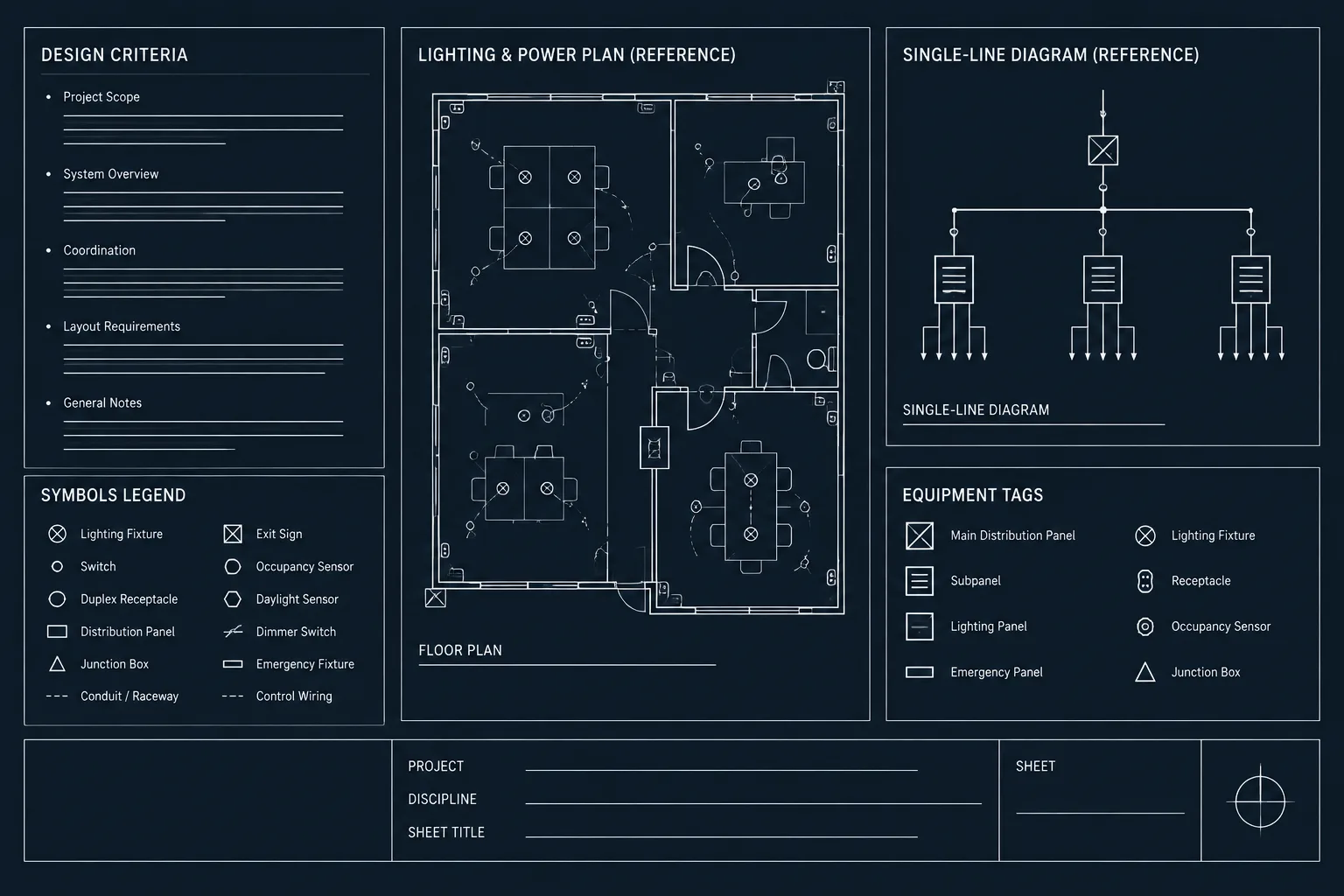
An electrical design criteria sheet in CAD establishes the documentation logic behind a drawing set. It gives project participants a common place to interpret assumptions, source information, system terminology, drafting conventions, and unresolved coordination items.
The most effective criteria sheets are project-specific and easy to audit. They direct users to the controlling plans, diagrams, schedules, calculations, or specifications without duplicating those documents. The guidance below focuses on structuring this information so that it remains clear as the drawing set develops.
An electrical design criteria sheet gives drawing users a concise explanation of the assumptions, references, and documentation rules behind an electrical drawing set. It can help reviewers understand how systems are represented, help drafters apply consistent notation, and help project teams identify information that still requires confirmation.
The sheet should not become a collection of copied specifications, unexplained calculations, or generic notes carried from an unrelated project. Its value comes from presenting project-relevant information in a controlled, readable format that coordinates with plans, diagrams, schedules, and details.
What an Electrical Design Criteria Sheet Does
A design criteria sheet records the framework used to develop the electrical documents. Depending on the project, that framework may include system descriptions, drawing conventions, environmental assumptions, coordination responsibilities, and references to calculations maintained elsewhere.
The sheet can serve several audiences:
- Drafters use it to apply consistent tags, linework, terminology, and system classifications.
- Designers and engineers use it to communicate assumptions and identify items requiring verification.
- Reviewers use it to understand the intended relationship among plans, schedules, and diagrams.
- Other disciplines use it to find electrical coordination requirements without searching every sheet.
- Record-document teams use it to distinguish original criteria from later verified conditions.
A criteria sheet provides context, but it does not replace project calculations, specifications, equipment submittals, applicable requirements, or professional review.
Criteria, Notes, Specifications, and Calculations Are Different
One of the most important drafting decisions is determining where information belongs. Repeating the same statement in several places increases the chance that one copy will become outdated.
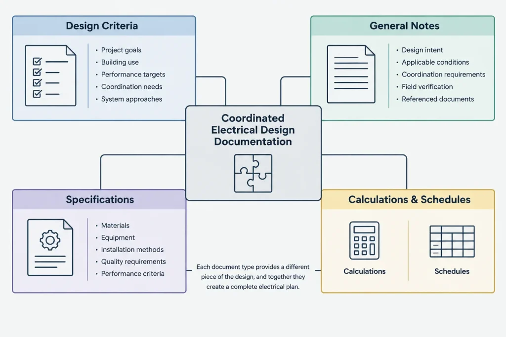
| Document element | Primary purpose | Typical content |
|---|---|---|
| Design criteria | Explain the basis and assumptions used to prepare the drawings | System categories, source assumptions, coordination approach, drawing conventions |
| General notes | Provide instructions that apply broadly to the drawing set | Interpretation notes, coordination directions, and documentation requirements |
| Sheet notes or keynotes | Address a location, plan, diagram, or condition | Area-specific work, equipment interfaces, and exceptions |
| Specifications | Define detailed product, material, execution, and quality requirements | Performance requirements, submittals, installation provisions, and testing expectations |
| Calculations | Record the technical analysis supporting design decisions | Load studies, lighting analysis, fault studies, and other engineering evaluations |
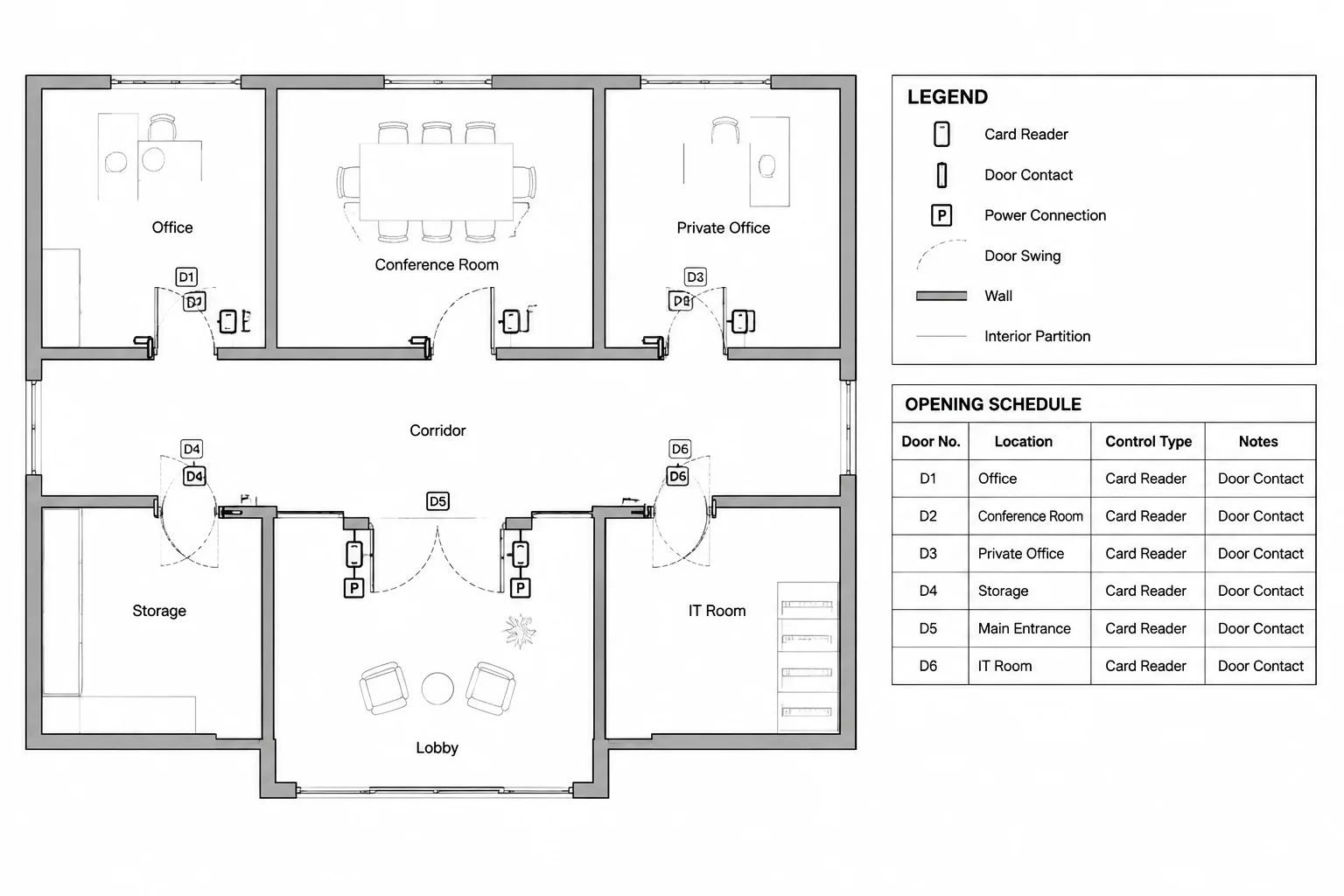
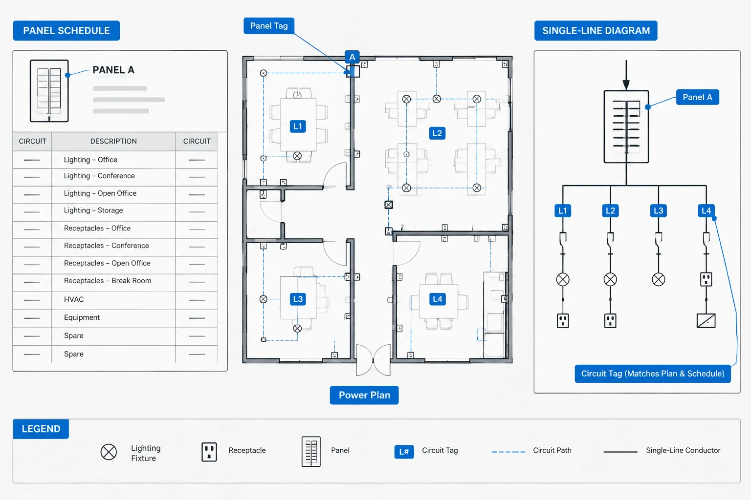
| Schedules | Organize repeated project data | Equipment identifiers, circuit information, fixture types, and connection data |
When a detailed requirement already resides in another controlled document, the criteria sheet should identify the relationship rather than reproduce the entire requirement. This reduces contradictions and keeps the CAD sheet focused.
Useful Content Categories
System Overview
Begin with a short description of the electrical systems represented in the set. Use the same names found in sheet titles, legends, schedules, and diagrams. If drawings distinguish normal power, backup power, lighting controls, communications, or other systems, the criteria sheet should follow that classification.
A system overview is not a substitute for a single-line diagram or riser. It should explain the document structure rather than repeat every connection.
Sources and Distribution Assumptions
Record the source information used to develop the documents and clearly identify its status. For example, information may be based on an owner record, a utility response, an equipment submittal, a field observation, or a design assumption awaiting confirmation.
Avoid presenting an unverified value as an established condition. Where source data may change, use a visible status phrase and assign a coordination action. The affected plans, schedules, and diagrams should use the same terminology.
Drawing Conventions
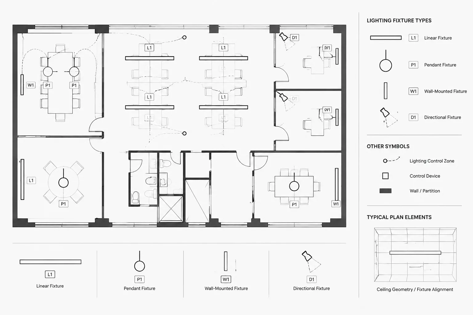
The criteria sheet can explain conventions that affect interpretation across several sheets. Relevant topics may include:
- How existing, new, relocated, and removed work is differentiated.
- Whether routing linework indicates exact geometry or diagrammatic intent.
- How concealed and exposed pathways are distinguished.
- How equipment, circuits, feeders, and raceways are tagged.
- Where continuation references and detail callouts are used.
- Which information is shown on plans versus schedules or diagrams.
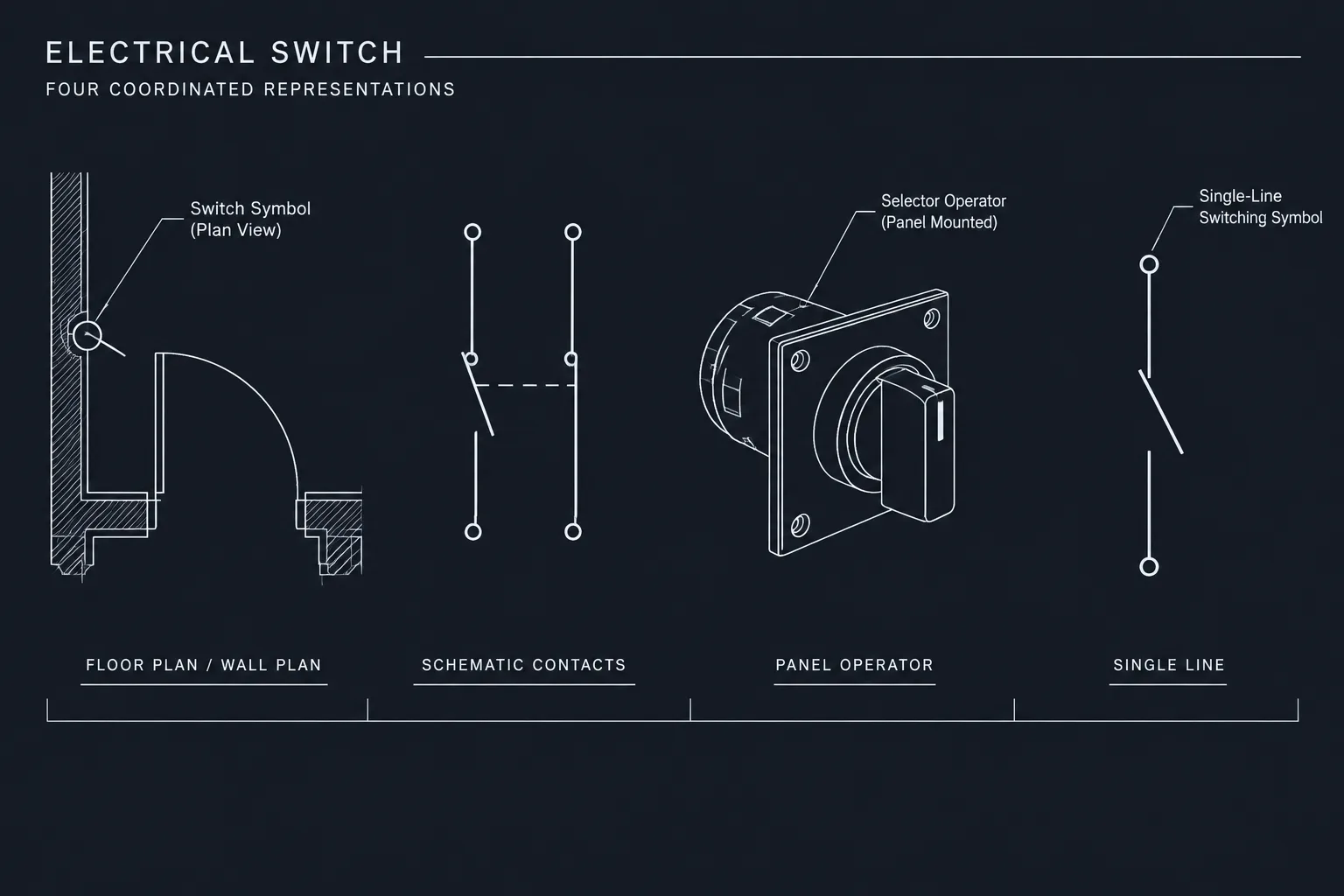
Keep these statements consistent with the symbol legend and actual plotted graphics. A convention described in text but not followed on the drawings creates uncertainty.
Coordination and Responsibility
Criteria notes can identify coordination interfaces, but responsibility language should be specific. Broad phrases such as “coordinate all work” provide little guidance. Instead, state what information must be coordinated and where the controlling information is documented.
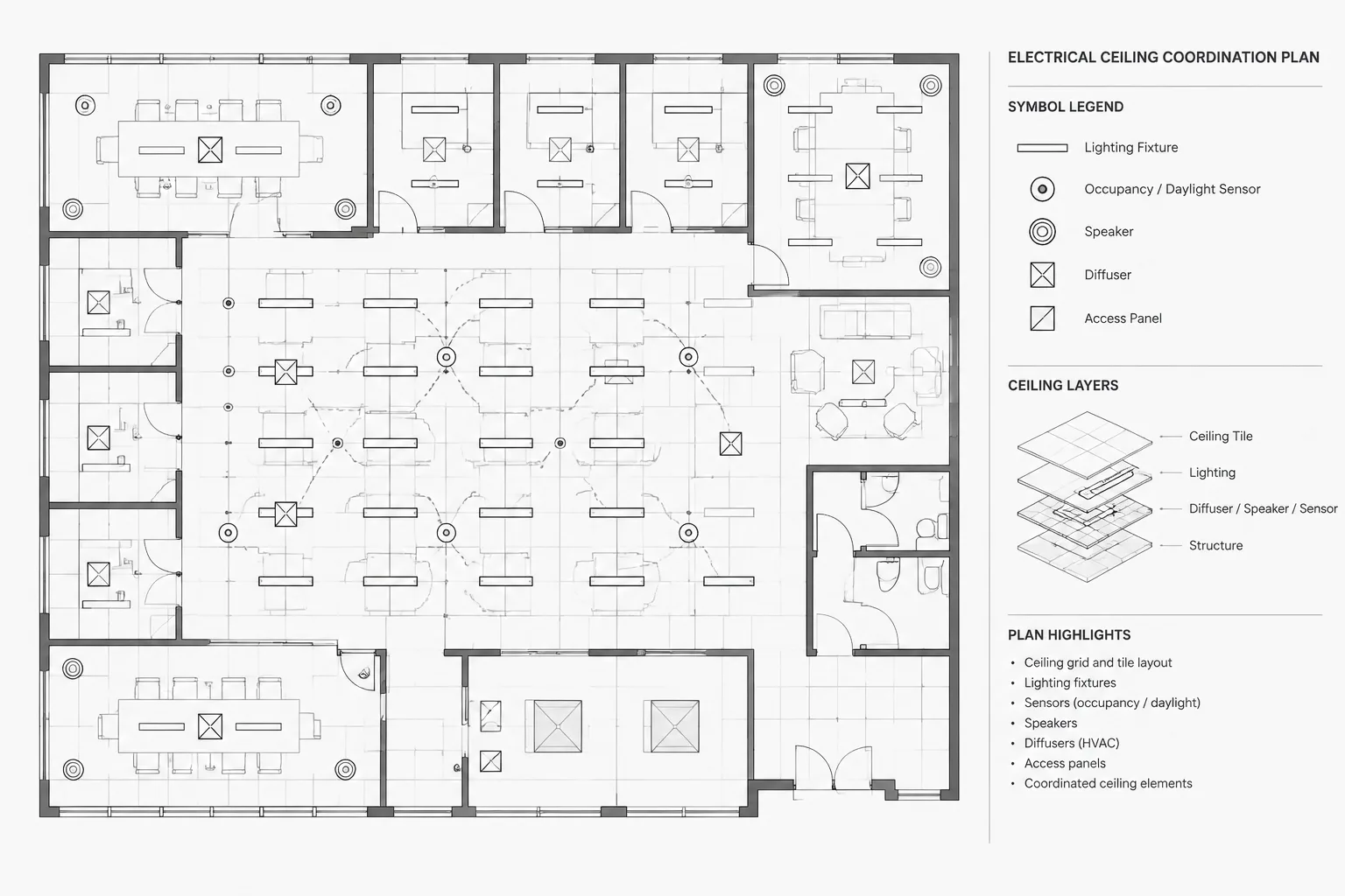
Common interfaces include architectural room data, reflected ceiling layouts, mechanical equipment connections, structural openings, equipment access zones, technology systems, and utility service information. If work is by an owner, vendor, utility, or another discipline, use consistent scope language throughout the set.
Items Requiring Confirmation
Open items should be visible rather than buried in paragraphs. A compact confirmation list can identify the item, its current basis, the responsible source, and the drawings that may be affected.
Do not leave internal drafting comments or informal placeholders in an issued sheet. Convert unresolved matters into controlled notes, an issue log, or another project-approved tracking method.
Building the Sheet in CAD
Use a Clear Information Hierarchy
Divide the sheet into short, named sections instead of creating one long note block. Headings such as “System Basis,” “Drawing Conventions,” “Coordination,” and “Pending Information” make the sheet easier to scan.
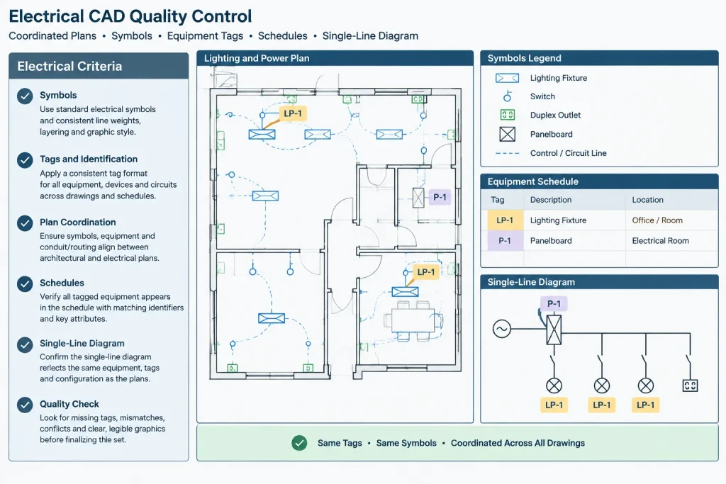
Use the project’s established text styles, spacing, and numbering method. Criteria text should remain readable at the intended plot size and should not depend on color alone to communicate status.
Keep Repeated Data Linked by Identifier
When criteria relate to a particular panel, transformer, switchboard, control panel, or other item, reference the same equipment identifier used on the plan, schedule, and diagram. Avoid creating a second descriptive name that cannot be traced to the drawing set.
CAD attributes or structured note fields can help maintain identifiers, but automation should be checked after block replacement, data extraction, file exchange, and plotting. A populated field is not proof that its content is correct.
Separate Project Notes from Office Masters
Maintain reusable language in a controlled office source, but copy only relevant sections into the project. Each imported note should be reviewed for terminology, scope, and compatibility with the current drawings.
Project-specific edits should not silently alter the master source. Conversely, updates to an office master should not overwrite verified project decisions without review.
A Practical Coordination Workflow
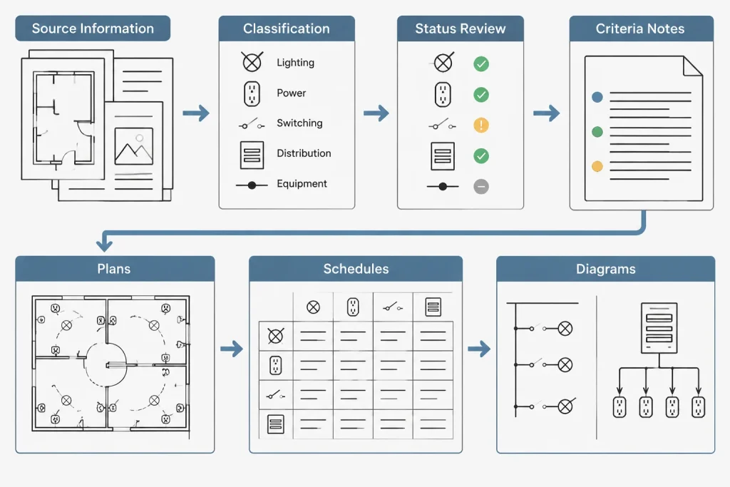
- Collect source information. Identify owner criteria, consultant backgrounds, utility information, equipment data, calculations, and applicable project requirements.
- Classify each statement. Decide whether it is a criterion, general note, specification requirement, calculation result, schedule entry, or unresolved item.
- Assign a source and status. Mark whether information is verified, assumed, preliminary, vendor-provided, or awaiting coordination.
- Draft concise sections. Use short statements and defined terminology rather than dense narrative paragraphs.
- Cross-check the drawings. Compare equipment names, system names, status graphics, abbreviations, and references against plans, diagrams, legends, and schedules.
- Review each issue. Update changed assumptions and remove resolved placeholders before publishing the next drawing package.
Common Problems to Avoid
- Generic inherited notes: Text from an older project may describe systems or responsibilities that do not exist in the current set.
- Conflicting terminology: A system should not have one name on the criteria sheet and another in the legend or one-line diagram.
- Untraceable technical values: Values should have a verified project source and should be coordinated wherever they appear.
- Duplicated requirements: Repeating detailed specification language on drawings makes revision control more difficult.
- Hidden assumptions: A drafting assumption that affects layout, capacity, or scope should be visible to the appropriate reviewer.
- Stale pending notes: Temporary status language should be checked at every issue milestone.
Final Review Checklist
- Does every section apply to the current project?
- Are system and equipment names consistent across the set?
- Can each important assumption be traced to a source or responsible party?
- Are unresolved items clearly distinguished from verified information?
- Do plans, legends, diagrams, schedules, and criteria use matching conventions?
- Has duplicated or specification-level text been removed?
- Is the sheet legible in the final plotted or exported format?
- Have revision-sensitive statements been reviewed for the current issue?
A well-organized electrical design criteria sheet is more than a page of general notes. It is a coordination tool that explains the basis of the drawings, exposes unresolved assumptions, and gives the rest of the electrical set a consistent documentation framework.
Strengthening Traceability Across the Drawing Set
A criteria statement becomes more useful when a reviewer can trace it to the drawing content it affects. References should use the same sheet names, equipment identifiers, system labels, and status terms found elsewhere in the project documents. This creates a visible path from the design basis to the plans, diagrams, schedules, and coordination records.
Traceability is especially important when information changes. If a source assumption is revised, the team should be able to identify the related drawing elements without relying on memory or searching unrelated note blocks.
Use Controlled Status Language
Status terms should have distinct meanings within the project workflow. Terms such as assumed, pending confirmation, provided by others, and verified should not be used interchangeably. The criteria sheet should describe the current basis without implying that preliminary information has received final approval.
Where an open item affects several documents, use consistent wording wherever that status appears. Informal comments, clouded reminders, and temporary drafting text should not be the only record of an unresolved decision.
Design the Sheet for Maintenance
The CAD layout should support revision rather than treat the criteria as a static narrative. Separate subjects into compact note groups, keep headings independent from body text, and avoid manually aligning paragraphs with spaces. Consistent text styles and spacing make later edits easier to review and less likely to disturb the sheet.
Reusable blocks, fields, or linked data can improve consistency, but they require quality control. Review displayed values, references, wrapping, and plot output after source files or block definitions change.
Review Criteria by Impact
Not every edit has the same effect. A wording correction may be limited to the criteria sheet, while a changed system assumption may affect equipment tags, schedules, diagrams, plan annotations, and coordination notes. During issue review, classify revisions by the documents they influence and confirm that every affected location has been checked.
This impact-based review helps keep the criteria sheet connected to the actual design documents instead of allowing it to become an isolated page of background information.
Frequently Asked Questions
What belongs on an electrical design criteria sheet?
Include project-relevant assumptions, system classifications, source descriptions, drawing conventions, coordination responsibilities, and visible status information. Detailed product requirements, calculations, and repeated schedule data generally belong in their controlling documents.
Is a design criteria sheet the same as a general notes sheet?
No. Design criteria explain the basis and assumptions used to prepare the documents. General notes provide instructions that apply broadly to the drawing set. A project may combine related material on one sheet, but the information should remain clearly categorized.
How should unverified information be shown?
Identify it with controlled status language, name the source or responsible party when appropriate, and indicate which drawing content may be affected. Do not present an assumption as a confirmed existing condition.
Should calculations be placed on the criteria sheet?
The sheet may identify the calculation basis or point users toward a maintained analysis, but it should not become an uncontrolled duplicate of the calculation record. Any summarized result must remain coordinated with its source.
How can CAD users prevent criteria notes from becoming outdated?
Review imported master notes for project relevance, use consistent identifiers, track pending information, and include the criteria sheet in each drawing issue review. Changes should be checked against plans, legends, schedules, and diagrams.
Can the same criteria sheet be reused on another project?
An office template can provide structure and approved terminology, but project content requires a fresh review. Unrelated systems, responsibilities, assumptions, and references should be removed rather than carried forward automatically.
Leave a Reply
You must be logged in to post a comment.