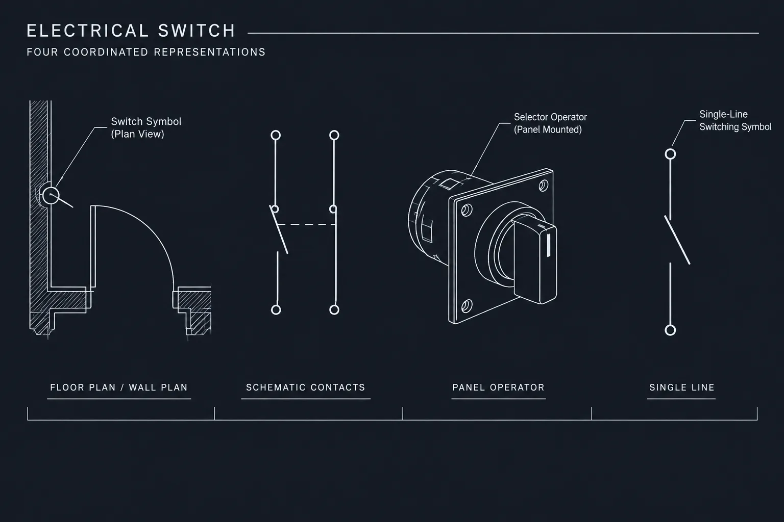
Electrical switch symbols in CAD must be interpreted in the context of the drawing where they appear. A wall-control symbol on a lighting plan communicates different information from a contact symbol in a control schematic or a switching-device symbol on a single-line diagram.
This reference explains how those representations differ and how CAD users can coordinate them without treating visually different symbols as unrelated devices. It is intended for symbol-library review, drawing production, cross-discipline checking, and educational comparison. Project legends, equipment documentation, and verified design requirements should remain the controlling references.
The word switch can describe several different drawing objects. On a lighting plan, it may be a wall control symbol placed beside a doorway. In a control schematic, it may appear as one or more contacts that show operating logic. On an equipment layout, it may represent a selector switch or other operator mounted on a panel face.
These symbols are related, but they are not interchangeable. Each drawing type communicates a different part of the design. A well-managed CAD set connects those representations through consistent tags, descriptions, and cross-references rather than forcing one graphic symbol to serve every purpose.
Why switch symbols change between drawing types
Electrical drawings use different abstraction levels. A floor plan emphasizes physical location and the area being controlled. A schematic emphasizes electrical behavior. An elevation emphasizes physical arrangement, while a schedule organizes descriptive information in rows and columns.
As a result, the same switching device may appear in several forms:
- A plan symbol showing where a wall control is located.
- Control linework indicating which luminaires or loads are associated with it.
- A schematic contact showing what changes state when the device operates.
- An elevation symbol showing an operator on an enclosure or wall station.
- A schedule entry describing the device type, function, or associated system.
The graphic form should suit the purpose of the view. Coordination comes from shared identification, not necessarily identical geometry.
Common switch representations
| Drawing context | Primary information | Typical CAD representation | Important coordination item |
|---|---|---|---|
| Lighting or power plan | Location and controlled load | Compact plan symbol, tag, and optional control line | Room, mounting context, and controlled fixtures or equipment |
| Control schematic | Operating logic and contact state | Contact symbols connected by schematic linework | Device tag, contact identity, and related coil or operator |
| Ladder diagram | Sequence of control functions | Contacts arranged along rungs | Cross-references and state conventions |
| Panel or station elevation | Physical arrangement of operators | Front-view symbol with label or device identifier | Location, nameplate text, and schematic reference |
| Single-line diagram | System-level switching or isolation | Simplified switching-device symbol | Equipment identity and relationship to sources and loads |
| Schedule or device list | Organized descriptive data | Text record rather than a graphic symbol | Exact agreement with tags used elsewhere |
Plan symbols show location and control intent
On a floor plan, a switch symbol is normally placed where the control is intended to be located. The symbol may be accompanied by a letter, number, or other project-defined modifier that distinguishes its function. Because symbol conventions vary, the legend should explain every modifier that is not immediately clear.
Control linework can connect a switch to lighting fixtures, relays, control zones, or other loads. This linework usually communicates association rather than the literal route of conductors or raceway. Its linetype, layer, and meaning should therefore be defined in the drawing legend or project drafting standard.
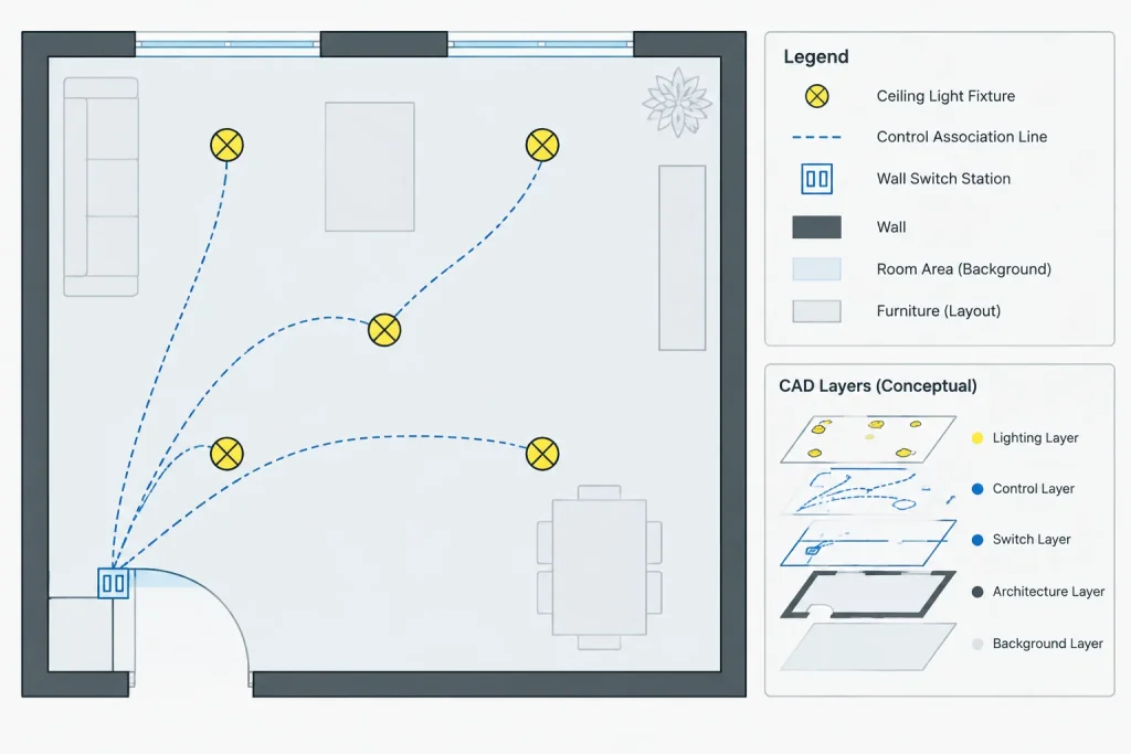
In congested areas, avoid moving the symbol so far from its intended location that it becomes misleading. If an offset is necessary, use a leader, station outline, or another clear graphic method. A reader should be able to distinguish the device location from the objects it controls.
Multi-device wall stations
Several controls may share one wall location. The plan can show them as a grouped station, adjacent symbols, or a single station symbol with an identifier. Whichever method is selected, it should answer two separate questions: where is the station, and what functions are included?
A grouped block can improve drafting consistency, but it should not hide necessary distinctions. If individual controls operate different zones, scenes, loads, or systems, preserve those relationships in tags, notes, schedules, or control diagrams.
Schematic contacts describe behavior, not room location
A schematic switch symbol represents an electrical condition or action. Contacts may be shown in a defined reference state, but the meaning of that state must follow the project convention and the device documentation. Drafters should not assume that every symbol library uses the same state convention.
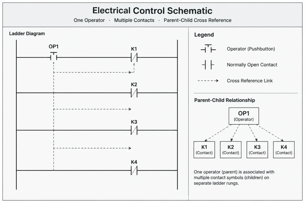
A device with multiple contacts may appear as separate symbols in different parts of a schematic. Those contacts still belong to the same physical operator. A shared device tag and contact cross-reference help the reader reconstruct that relationship.
This is an important difference from a floor plan. A plan may show one symbol for the physical device, while a schematic may show several contact elements because the diagram is documenting function rather than appearance.
Maintained and momentary actions
The drawing should distinguish maintained actions from momentary actions when that difference matters to the control sequence. Do not depend on subtle graphics alone if the distinction could be misunderstood. A description, tag suffix, legend entry, or device schedule can reinforce the intended behavior.
Similarly, a selector switch may have several labeled positions. Its schematic representation can require multiple contacts or a dedicated position diagram, while the elevation may show only the operator and its position labels.
Switching devices on single-line diagrams
A single-line diagram presents the distribution system at a higher level. Switching and isolation devices are shown in relation to sources, buses, feeders, transformers, and loads. The symbol identifies a functional point in the system, but it does not usually explain all mechanical or control details.
Avoid using a generic switch graphic when the drawing needs to distinguish among materially different device functions. At the same time, do not add schematic-level detail that makes the single-line difficult to read. Supporting notes, schedules, control diagrams, or equipment documentation can carry information that does not belong in the system overview.
Building a coordinated CAD symbol family
A practical symbol library can treat the different representations as a related family rather than unrelated blocks. The plan symbol, schematic contacts, elevation operator, and diagram symbol may use different geometry while sharing a consistent identification structure.
Useful block data fields can include:
- Device tag or control-station identifier.
- Functional description.
- Drawing representation type.
- Associated load, zone, or equipment tag.
- Schedule key or specification reference.
- Source detail or schematic reference.
- Library status and revision note.
Not every field needs to display beside the symbol. Some information can remain available for schedules, checking, or data extraction. Visible attributes should be limited to what the drawing reader needs in that view.
A CAD workflow for coordinating switch representations
1. Identify the drawing purpose
Decide whether the view is documenting location, electrical logic, physical arrangement, or system topology. Select the symbol type based on that purpose rather than choosing the first block named “switch.”
2. Assign a stable identifier
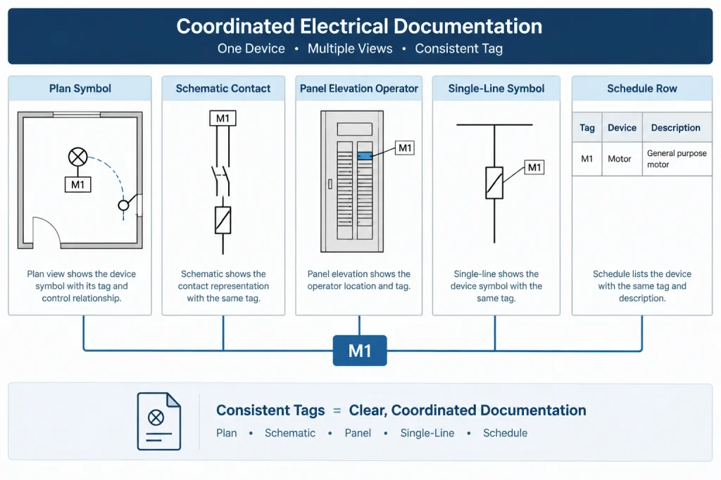
Use a device or station tag that can be carried across plans, diagrams, elevations, and schedules. If individual contacts require suffixes or contact identifiers, keep the parent-device relationship recognizable.
3. Define graphic conventions
Place symbols, control lines, contact graphics, tags, and cross-references on appropriate layers. Confirm that their colors, lineweights, and linetypes remain distinguishable when plotted and when architectural backgrounds are screened.
4. Coordinate related loads
Check that the plan association agrees with the control diagram and any fixture, equipment, or device schedule. A switch connected graphically to one zone but described as controlling another creates a documentation conflict even when both drawings look complete.
5. Review repeated and grouped devices
Search for duplicate tags, untagged symbols, unexplained modifiers, and grouped stations with incomplete descriptions. Also review mirrored or copied rooms, where control lines and tags may retain relationships from the source layout.
6. Test the plotted output
Inspect a PDF or print preview at the intended sheet presentation. Contact gaps, small modifiers, control linetypes, and station outlines can become unclear after plotting even when they appear correct at a close CAD zoom.
Frequent documentation problems
- Using a plan symbol in a schematic: The graphic indicates a device but does not communicate contact behavior.
- Using one block for every switch type: Important functional differences become dependent on informal notes.
- Missing parent-child relationships: Multiple schematic contacts cannot be traced back to one operator or device.
- Unexplained tag modifiers: Readers cannot tell whether a suffix indicates function, location, grouping, or drawing sequence.
- Literal-looking control lines: Association linework is mistaken for a physical wiring route.
- Plan and schedule disagreement: The location tag exists, but its description or controlled load differs elsewhere.
- Library blocks treated as verified design content: Generic geometry is used without checking project conventions, equipment documentation, or design requirements.
Final review principle
A switch symbol should answer the question asked by its drawing. Plans answer where the control is and what it serves. Schematics answer how contacts behave within the circuit. Elevations answer how operators are arranged. Single-line diagrams answer where switching functions occur in the larger electrical system.
Do not judge coordination by graphic similarity alone. The strongest drawing sets use the appropriate representation in each view and connect those representations with stable tags, clear legends, accurate cross-references, and coordinated schedules. Any downloaded CAD block should be reviewed and adapted to the project’s drafting conventions and verified design information before use.
How to trace one switch across a drawing set
When reviewing several drawing types, begin with the device identifier rather than the symbol shape. Locate the switch or control station on the plan, then follow its tag into the applicable schedule, schematic, elevation, or system diagram. Each view should add information while preserving the identity of the device.
A useful coordination trail typically connects the physical location, functional description, controlled load, schematic behavior, and operator arrangement. Not every drawing must show all of these items. The goal is for the combined documentation to provide a consistent account without conflicting tags or ambiguous associations.
Evaluate a CAD block before adding it to a library
- Confirm its drawing context: Determine whether the block was created for a plan, schematic, elevation, or system diagram.
- Review the insertion point: Check whether placement will clearly represent the device location or connection point.
- Inspect attributes: Identify which fields are visible, which support schedules, and which require project-specific values.
- Check layer behavior: Make sure symbol geometry, annotations, and association lines can be controlled independently where needed.
- Compare plotted clarity: Verify that contacts, modifiers, tags, and linework remain distinguishable in the issued drawing format.
- Remove unsupported meaning: Do not retain a modifier or graphic convention unless it is defined by the project documentation.
Separate identity from representation
A strong CAD library treats the device identity as coordinated data and the symbol as a view-specific representation. This makes it possible to revise plan graphics, schematic contacts, or elevation operators without breaking the relationship among drawings. It also helps reviewers distinguish a drafting change from a change to the intended device function.
Frequently asked questions
Can the same switch block be used on a plan and a schematic?
Usually, the representations should differ because the drawings communicate different information. A plan block emphasizes location and control association, while a schematic symbol communicates contact behavior. Shared tags and cross-references should connect them.
What does a control line from a wall switch represent?
It commonly indicates an association between the control and a fixture, zone, relay, or other load. It should not automatically be interpreted as the physical conductor or raceway route. The project legend should define its meaning.
Why can one physical switch have several schematic contacts?
A device can operate more than one contact or function. A schematic may place those contact symbols where they are needed to explain the control logic, even though the plan shows a single physical operator. Consistent parent-device tags help preserve the relationship.
How should maintained and momentary switch actions be documented?
Use the project’s defined symbol, tag, description, or schedule convention. If the graphic difference could be overlooked, reinforce it with clear text or a coordinated device record.
Should a single-line diagram include detailed switch control logic?
A single-line diagram generally focuses on the device’s role within the larger distribution system. Detailed contact logic is better documented in the appropriate control schematic or supporting diagram when that information is required.
What should be checked when switch symbols are copied between rooms?
Review the device tag, controlled load, control line, station grouping, schedule entry, and cross-references. Copied geometry can retain associations or descriptions that belonged to the original location.
Is a downloaded switch symbol ready for direct project use?
Not without review. Confirm that its graphic meaning, attributes, layers, tags, and reference-state conventions agree with the project documentation and verified design information.












Leave a Reply
You must be logged in to post a comment.