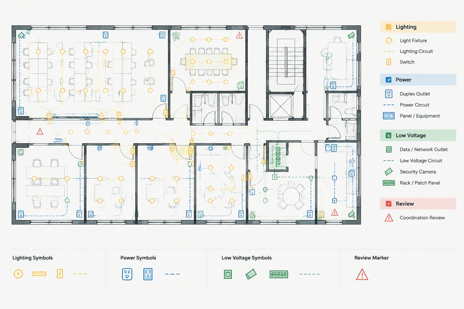
An electrical CAD overlay review brings related plan information together without collapsing every discipline into one unreadable drawing. It gives reviewers a structured way to compare device locations, equipment connections, routing, annotations, and background revisions across lighting, power, and low-voltage documents.
This guide explains how to prepare source drawings, organize focused comparison passes, document findings, and confirm that corrections appear in the responsible production files. The emphasis is on repeatable CAD coordination rather than informal visual checking.
An electrical CAD overlay review compares related drawings in a common coordinate space so designers and drafters can identify conflicts that are difficult to see on separate sheets. A lighting plan may appear complete by itself, while an overlay reveals that a fixture, receptacle, control device, cable tray, or equipment connection competes with another system for the same location.
The purpose is not simply to display every electrical layer at once. A useful overlay is a controlled review environment in which selected systems are compared, conflicts are classified, and decisions are carried back into the project drawings. This process can improve consistency among lighting, power, fire alarm, communications, security, and equipment connection documents.
What an Electrical CAD Overlay Review Can Reveal
Separate plan types divide information into readable sheets, but that division can hide relationships. Overlay review temporarily reconnects those relationships.
Typical findings include:
- Devices from different systems occupying the same wall or ceiling location.
- Lighting fixtures conflicting with ceiling-mounted sensors, speakers, detectors, cameras, or access panels.
- Receptacles that do not correspond with equipment shown on another plan.
- Control devices located far from the fixtures or zones they are intended to serve.
- Duplicate equipment connections shown on more than one electrical plan.
- Raceway or cable tray routes crossing equipment access areas.
- Inconsistent room names, equipment tags, or plan extents.
- Devices placed against outdated architectural or equipment backgrounds.
An overlay is primarily a coordination tool. It does not replace the design review, field verification, applicable project criteria, or evaluation by the responsible design professional.
Prepare the Drawings Before Comparing Them
An overlay review is only reliable when the source files share the same placement and reference conditions. Misaligned backgrounds can create apparent conflicts that do not exist.
Confirm a Common Coordinate Basis
Verify that each electrical plan references the same architectural floor plan, origin, orientation, and building location. Do not manually drag one plan over another until it looks approximately aligned. Temporary visual alignment can conceal a deeper base-point or reference problem.

Check Background Revisions
Confirm that the compared plans use compatible architectural, structural, ceiling, and equipment backgrounds. A lighting plan based on a newer ceiling layout should not be treated as directly coordinated with a power plan based on an older room arrangement.
Standardize the Review Display
Create a temporary review configuration that makes each system visually distinct. Color can be helpful on screen, but lineweight, linetype, screening, and labels should also support interpretation. Color alone may not remain understandable in monochrome plots or exported review files.
Use Focused Overlay Passes
Turning on every discipline and annotation layer often produces an unreadable image. Compare a limited number of related systems during each pass.
| Review pass | Primary comparison | Items to examine |
|---|---|---|
| Lighting and ceiling systems | Lighting plan against other ceiling-mounted devices | Fixture positions, sensors, detectors, speakers, cameras, access panels, ceiling features, and mounting zones |
| Lighting and power | Lighting controls and connections against branch-power documentation | Control locations, connection points, panel references, home runs, and duplicated circuit information |
| Power and equipment | Receptacles and equipment connections against equipment layouts | Missing connections, duplicated outlets, displaced equipment, disconnect references, and tag consistency |
| Power and low voltage | Power devices against communications, security, and control devices | Closely coordinated outlets, device groupings, workstation services, and overlapping symbols |
| Routing and equipment space | Raceways or cable trays against equipment and building elements | Routing continuity, access areas, vertical transitions, penetrations, and congestion |
| All-system annotation | Tags, leaders, notes, and match lines across plan types | Duplicate labels, contradictory references, clipped text, and inconsistent naming |
The exact passes should reflect the project scope. A small renovation may need only lighting, power, and architectural comparisons, while a larger project may require separate reviews for security, communications, fire alarm, controls, and distribution routing.
A Practical Electrical CAD Overlay Workflow
1. Define the Review Area
Start with a floor, wing, room group, or enlarged area that can be reviewed without excessive visual clutter. Record the source drawing names and issue status so the review can be reproduced.
2. Load Files as References
Use referenced source drawings rather than copying their geometry into a temporary file. References reduce accidental editing and make it easier to reload updated plans. Keep the overlay file separate from production sheets unless the project workflow specifically calls for another arrangement.
3. Isolate Relevant Layers
Display only the systems needed for the current pass. Hide title blocks, redundant borders, construction grids, dense hatches, and notes that do not support the comparison. Retain enough architectural context to identify rooms, walls, doors, ceilings, and major equipment.

4. Assign a Clear Visual Hierarchy
Keep one system visually dominant and screen or simplify the comparison system. For example, lighting geometry may remain prominent while low-voltage devices appear in a contrasting review color. Reverse the hierarchy during a later pass if necessary.
5. Review Spatial and Data Relationships
Do not limit the check to symbol collisions. Compare device tags, circuit references, equipment identifiers, room associations, system status, and continuation notes. Two symbols may be spatially acceptable but still contain contradictory information.
6. Mark Findings Without Altering Sources
Place review clouds, numbered markers, or comments on dedicated coordination layers in the overlay file. Avoid moving a source symbol during the review merely to make the conflict disappear. The responsible drawing should be identified before a production change is made.
7. Assign and Resolve Each Finding
Record which plan owns the item, what information must be confirmed, and where the final correction will occur. Some findings require a drafting correction; others require design input or coordination with another discipline.
8. Reload and Verify
After production drawings are updated, reload the references and repeat the affected comparison. A closed comment should mean that the coordinated drawings now agree, not simply that a review marker has been deleted.
Build a Useful Conflict Log
A concise conflict log prevents overlay comments from becoming disconnected markups. Each entry should contain enough information for another team member to locate and understand the issue.
- A unique comment identifier.
- Building, level, room, or grid-area reference.
- The systems or drawings being compared.
- A short description of the conflict.
- The drawing or discipline responsible for the response.
- The current status, such as open, under review, revised, or verified.
- A note describing the final resolution when needed.
Avoid vague comments such as “coordinate device.” A stronger note identifies the devices involved and the inconsistency that requires resolution. The conflict log should support decisions, not merely count markups.

Common Causes of False Conflicts
Not every apparent collision represents a design problem. Before issuing a comment, check for:
- Different plan cut planes or mounting surfaces.
- Symbols intentionally offset from their physical locations for readability.
- Separate devices located at different elevations.
- Diagrammatic routing that does not represent an exact installed path.
- Duplicate-looking symbols that serve different systems.
- Phased, alternate, future, or existing work displayed together.
- Unloaded references or layers that remove important context.
Where a symbol is diagrammatically offset, a leader, mounting note, or other location reference should make the intent clear. Reviewers should distinguish drawing clarity issues from actual spatial conflicts.
Coordinate CAD Blocks as Well as Locations
Overlay reviews can expose problems in the CAD block library. Symbols representing similar devices may have inconsistent insertion points, orientation rules, attribute positions, or extents. These differences can make a coordinated device group appear misaligned even when the intended locations match.
When a recurring block problem is found, correct the controlled library definition and evaluate affected project instances. Repeatedly editing individual symbols may leave the same defect in other drawings. Any block replacement should preserve required tags, attributes, and project-specific data.
Overlay Review Checklist
- Are the drawings aligned to the same verified reference system?
- Do the plans use compatible background revisions?
- Are only the systems needed for the current review visible?
- Can each system be distinguished without relying entirely on color?
- Have both symbol locations and associated data been checked?
- Are phased and future items clearly separated from current work?
- Does every markup identify an owner or required decision?
- Were revised drawings reloaded and visually verified?
- Have temporary review graphics been kept out of final production plots?
Make Overlay Review Part of Issue Control
The most valuable electrical CAD overlay review occurs at planned coordination points, not only immediately before a drawing issue. Reviews are especially useful after significant architectural background changes, equipment layout updates, ceiling revisions, or major electrical design changes.
A disciplined overlay process connects CAD geometry, device data, and drawing responsibility. By comparing related systems in controlled passes, documenting findings, and verifying corrections, the project team can produce electrical plans that are easier to read and more consistent across the drawing set.
Turn Overlay Findings into Controlled Drawing Changes
Finding a conflict is only the beginning of the coordination process. The review record should distinguish between a geometric conflict, a data inconsistency, an outdated background, an unclear symbol, and a design question. That classification helps the team route each finding to the person responsible for resolving it.
Identify the Authoritative Drawing
Related plans may show the same device for different documentation purposes. Before changing anything, determine which drawing controls the location, connection, tag, or system information in question. Supporting plans should then be checked for references that must remain consistent with that authoritative source.
Preserve Review Evidence
A useful coordination record should make the review reproducible. Retain the drawing identifiers, revision status, visible systems, review area, and markup references used during the comparison. This context helps another reviewer understand whether a later difference represents a new conflict or simply a change in the source documents.
Separate Drafting Corrections from Design Decisions
- Drafting correction: A misplaced label, inconsistent tag, duplicated symbol, clipped note, or incorrect layer assignment can often be corrected in the responsible drawing.
- Background coordination: A device based on an obsolete room, ceiling, or equipment arrangement requires confirmation of the current reference file.
- Design decision: A conflict involving system intent, equipment access, device selection, or routing responsibility should be returned to the appropriate design professional.
- Drawing clarification: An apparent conflict caused by diagrammatic placement may require a leader, note, or clearer graphical convention rather than relocation.
Apply a Clear Closeout Test
A coordination item is not resolved merely because its markup has been removed. Closeout should confirm that the responsible source was revised, dependent references were reloaded, related plans remain consistent, and temporary review graphics will not appear in issued documentation.
Electrical CAD Overlay Review FAQ
Which drawings should be included in an overlay review?
Include only the current drawings and backgrounds needed for the comparison being performed. Lighting, power, reflected ceiling, equipment, communications, security, fire alarm, and routing plans may be relevant, but displaying all of them simultaneously can obscure the relationships under review.
Why can correctly aligned drawings still show false conflicts?
Symbols may be diagrammatically offset, located on different mounting surfaces, or associated with different phases of work. Differences in plan representation, visible layers, and background revisions can also make coordinated items appear to collide.
Should the overlay file replace the production drawings?
Normally, the overlay functions as a review environment rather than the authoritative project document. Corrections should be made in the responsible source drawings and then checked again through reloaded references. Project-specific document controls may require a different arrangement.
How should conflicting device information be handled?
Determine which drawing owns the device location and which documents carry supporting references such as tags, circuits, controls, or equipment connections. Update the authoritative information first, then verify consistency wherever that information is repeated.
Can an electrical CAD overlay review replace design coordination?
No. An overlay can reveal spatial, graphical, and data inconsistencies, but it does not establish design intent or confirm field conditions. Questions requiring engineering judgment or coordination with another discipline should be directed to the responsible project professional.
How is a resolved overlay comment verified?
Reload the revised source references, restore the relevant review display, and repeat the affected comparison. Confirm that the conflict is corrected in the drawings and that the change has not created a new inconsistency elsewhere in the coordinated set.












Leave a Reply
You must be logged in to post a comment.