
Electrical wall elevations supplement floor plans by showing the vertical relationships among electrical devices, architectural features, millwork, and equipment. This guide explains how to build readable elevation views, coordinate identifiers across drawings, manage dimensions, and document unresolved conditions without implying unverified installation requirements.
The emphasis is on CAD documentation and multidisciplinary review. Project-specific locations, products, accessibility criteria, and compliance requirements should be confirmed by the responsible design professionals before issue.
Electrical floor plans show where devices occur in a room, but they do not always communicate how those devices relate vertically to counters, cabinets, wall panels, equipment, and architectural finishes. Electrical wall elevations fill that documentation gap. They are especially useful where several outlets and controls must align with millwork, technology equipment, furniture, or other wall-mounted elements.
A useful elevation is not simply a collection of CAD blocks placed against a wall outline. It should connect each device to a plan location, identify its function, show the relevant architectural context, and make unresolved coordination visible. The drawing should also avoid implying dimensions or installation requirements that the design team has not verified.
When an Electrical Wall Elevation Is Useful
Drafting every wall in elevation can create unnecessary work. Elevations are most valuable where a floor plan cannot clearly express the installation intent. Common examples include:
- Receptacles, data outlets, and controls coordinated with casework or countertops
- Device groups located within decorative wall panels or tile patterns
- Power and communications connections serving displays or wall-mounted equipment
- Switches, dimmers, keypads, and control stations arranged in a shared location
- Outlets serving appliances or equipment within cabinets
- Back-of-house walls containing several electrical and low-voltage systems
- Rooms where accessibility, user operation, or architectural alignment requires review
The decision to create an elevation should be based on coordination risk rather than room importance. A small room with dense wall-mounted devices may need more elevation detail than a large room with only a few conventional outlets.
Start with a Coordinated Base
Use the current architectural elevation, interior elevation, or millwork drawing as the starting reference whenever possible. Relevant background information may include finished floor lines, countertops, cabinets, wall openings, equipment outlines, finish joints, and ceiling features.
Keep architectural geometry distinguishable from electrical work. A screened or lighter background allows electrical devices, tags, dimensions, and notes to remain prominent. Avoid tracing every decorative feature unless it affects device placement. Excess background detail increases file size and can obscure the information under review.
Confirm that the elevation corresponds to the correct wall and viewing direction. Label the room, wall reference, and related plan callout so reviewers can navigate between drawings without guessing.
Establish a Clear Elevation Reference
Vertical dimensions need an identifiable origin. A finished floor reference is commonly useful, but project conventions may use another documented datum. State the reference clearly and coordinate it with the architectural drawings.

Do not derive mounting information from the apparent height of a generic CAD block. The symbol graphic is representational; the dimension, keynote, schedule entry, or project note carries the documented placement requirement. If a mounting condition remains undecided, mark it for coordination rather than inserting an assumed value.
Represent Devices Consistently
Elevation symbols can be more pictorial than plan symbols, but they should still be simple and repeatable. Use a consistent graphic family for receptacles, switches, communications outlets, controls, junction boxes, and connection points. Excessively realistic manufacturer-style drawings can make a construction document harder to read and may incorrectly suggest a selected product.
A practical elevation block may include:
- A simplified face or outline
- An insertion point tied to the intended dimensioning reference
- A device type or identifier attribute
- A circuit, system, or connection attribute where needed
- A visibility option for different configurations, if the office workflow supports it
Before reusing a block from a library, check its units, insertion point, layer behavior, attribute definitions, and plotted appearance. A symbol that works on a floor plan may need a separate elevation representation.
Coordinate Plan and Elevation Identifiers
Every device shown in elevation should be traceable to the floor plan or another controlling drawing. Use the same device tag, equipment identifier, circuit reference, or keynote in both views. If a plan symbol represents a group of devices, the elevation should clarify what belongs to that group.
Plan and elevation graphics do not need to look identical, but their identifiers must agree. A receptacle tagged on the plan should not receive a different designation merely because its elevation block uses another shape.
For walls with many devices, consider a structured identification method:
- Assign a wall or elevation reference.
- Tag devices using the project’s established naming convention.
- Show circuit or system information only where it improves coordination.
- Direct the reader to schedules or details instead of repeating large amounts of data.
Show the Architectural Relationships That Matter
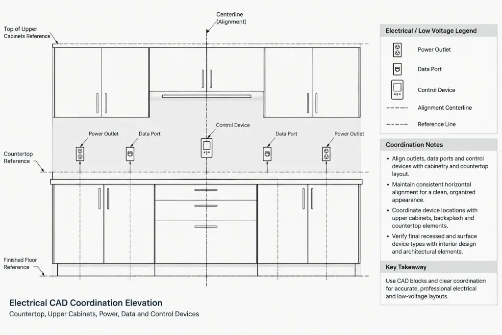
An electrical wall elevation should answer practical placement questions. Is the outlet above or below the counter? Is a control centered on a wall panel or aligned with adjacent devices? Does a data outlet conflict with a cabinet divider? Is a connection point concealed behind the equipment it serves?
Include enough architectural context to communicate these relationships. Useful reference elements may include:
- Finished floor and ceiling lines
- Countertop and backsplash extents
- Upper and lower cabinet outlines
- Equipment envelopes
- Doors, glazing, and trim affecting available wall space
- Finish joints where alignment is intentional
- Access panels or removable millwork sections
Avoid dimensioning electrical devices to architectural features that are not stable references. Decorative patterns, movable furniture, and conceptual equipment outlines may change. When their location controls the electrical work, identify the dependency with a note or coordination flag.
Dimension Without Overloading the Drawing
Dimensions should communicate design intent, not duplicate every value available elsewhere. Select a consistent method and apply it throughout the drawing set.
| Dimension type | Typical purpose | Coordination concern |
|---|---|---|
| Vertical location | Relates a device to a documented datum | Confirm whether the reference is to the centerline, edge, box, or another point |
| Horizontal location | Locates a device from a wall, opening, grid, or millwork feature | Use a reference that is controlled and constructible |
| Device spacing | Defines an intentional arrangement within a grouped station | Coordinate actual faceplates and product selections before finalizing |
| Alignment indication | Shows shared centerlines or relationships | Do not rely on visual alignment alone when it is important |
Where a project-wide mounting convention applies, a type designation or general note may be clearer than repeating the same dimension at each device. Exceptions should be explicitly identified. Always verify code-related, accessibility-related, and product-dependent placement criteria with the responsible project professionals.
Handle Grouped Devices Carefully
Switches, keypads, receptacles, data ports, and specialty controls are often shown as a neat row of generic symbols. The final arrangement may depend on faceplate compatibility, box configuration, wall construction, product dimensions, and separation requirements. The elevation should therefore distinguish between confirmed layout and conceptual grouping.
Use centerlines, grouping brackets, or notes to communicate the intended relationship. If exact spacing depends on selected equipment, say so in project-appropriate language rather than inventing a dimension. Where different trades provide adjacent devices, identify system responsibility through tags, layers, or notes while keeping the visual arrangement coordinated.
Use Layers to Support Review
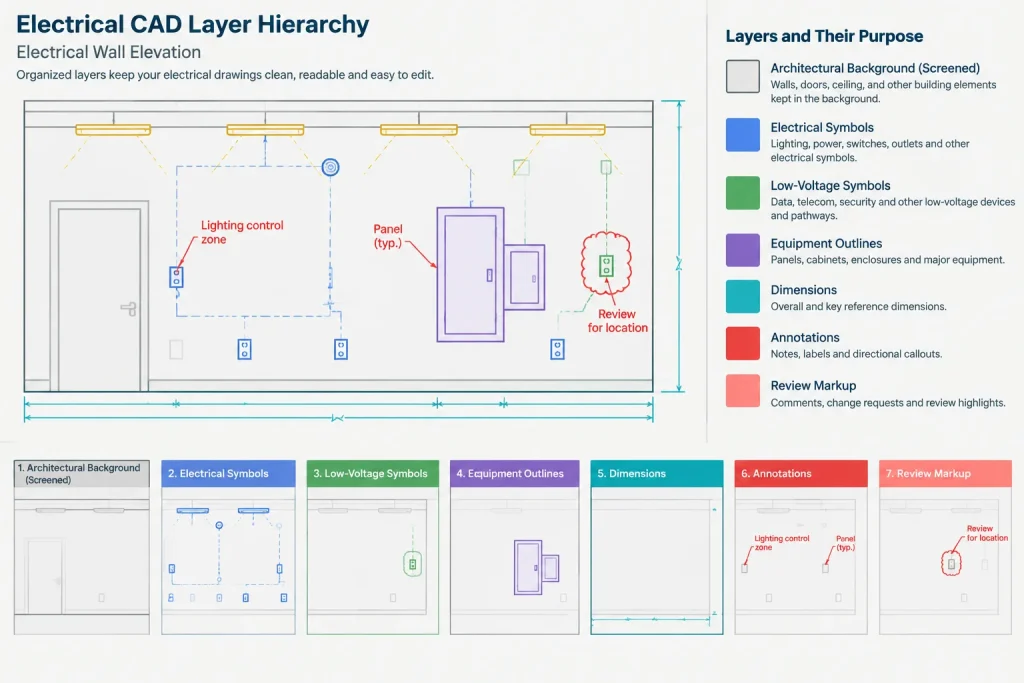
A wall elevation benefits from a simple layer hierarchy. Separate the architectural background, electrical devices, low-voltage devices, equipment outlines, dimensions, text, centerlines, and coordination markup as needed by the project.
This separation lets the drafter:
- Screen the background without weakening electrical symbols
- Temporarily isolate one system during coordination
- Hide unresolved markup from issued views
- Control lineweights for plotted readability
- Compare updates to architectural or millwork backgrounds
Do not place all elevation content on a single generic layer. That approach makes later revisions, plotting, and consultant coordination unnecessarily difficult.
Coordinate Revisions Across Drawings
A wall elevation can become unreliable when the floor plan changes but the elevation does not. Treat related views as a coordinated set. When a device moves, review its plan symbol, elevation symbol, circuiting, tags, schedule data, notes, and associated details.
A practical revision check includes:
- Verify that the wall and viewing direction still match the plan.
- Compare device quantities between plan and elevation.
- Check tag, circuit, and system consistency.
- Review updated millwork and equipment outlines.
- Confirm that dimensions reference current architectural geometry.
- Remove obsolete symbols, leaders, and hidden duplicate blocks.
- Plot the elevation at its intended sheet scale and inspect readability.
Common Drafting Problems
Untraceable devices
A device appears in elevation but has no corresponding plan symbol or identifier. Add a consistent tag or revise the plan so the relationship is explicit.
False precision
Detailed dimensions imply a finalized product or architectural condition that has not been selected. Show the coordination intent and flag the dependency instead.
Over-detailed blocks
Product-like graphics dominate the drawing and may suggest an unconfirmed manufacturer. Replace them with simplified, neutral representations unless a specific product drawing is required and verified.
Conflicting references
The elevation uses one datum while project notes or architectural drawings use another. Resolve the reference before issuing the sheet.
Duplicate information
Long notes repeat schedule data and become difficult to maintain. Keep the elevation focused on spatial relationships and refer to controlled schedules or details for supporting information.
A Reliable Wall-Elevation Workflow
- Identify walls where vertical coordination cannot be understood from the plan alone.
- Reference the current architectural, interior, or millwork background.
- Confirm the wall designation and viewing direction.
- Establish and label the drawing datum.
- Place simplified electrical and low-voltage elevation symbols.
- Match identifiers to the floor plan, schedules, and diagrams.
- Add only the dimensions and alignment references needed to communicate intent.
- Flag unresolved product, finish, equipment, or code-dependent conditions.
- Review grouped devices for constructible arrangement and trade responsibility.
- Plot-check the view and complete a cross-drawing coordination review.
Make the Elevation a Coordination Tool
The best electrical wall elevations reduce ambiguity without pretending that every condition is already resolved. They show how devices relate to the wall, identify what each item serves, and direct reviewers to the drawings or schedules that control additional information.
By using neutral CAD symbols, stable references, consistent tags, restrained dimensions, and disciplined revision checks, drafters can turn wall elevations into useful coordination documents rather than decorative views. Final locations, dimensions, products, and compliance criteria should still be verified for the specific project before the drawings are issued for construction.
Final Documentation Review
Before issuing an electrical wall elevation, review it as part of the complete drawing set rather than as an isolated detail. The plan establishes where the wall and devices occur, while the elevation explains their vertical arrangement and relationship to surrounding construction. Schedules, diagrams, and equipment information may provide additional identifiers or connection requirements.
A focused quality-control review should confirm that:
- Each elevation has a clear wall reference and viewing direction.
- Device identifiers agree with the floor plan and related schedules.
- Architectural and millwork backgrounds reflect the current coordination files.
- Dimensions use an identified datum and a clearly understood reference point.
- Grouped devices are shown as confirmed arrangements or marked as requiring coordination.
- Electrical graphics remain visually distinct from background geometry.
- Unresolved product, finish, equipment, and system interfaces are visible to reviewers.
- Obsolete blocks, duplicated symbols, and disconnected leaders have been removed.
Separate Design Intent from Product Detail
A wall elevation should communicate the required spatial relationship without becoming a substitute for verified product information. Neutral symbols are generally preferable while device selections remain open. When a selected item affects wall openings, faceplate arrangements, access, or adjacent finishes, the drawing team can coordinate that information through controlled details and schedules.
This separation makes revisions easier to manage. Stable design intent can remain visible while product-dependent information is updated through the appropriate project documents. It also reduces the risk that a generic CAD block will be interpreted as a confirmed installation detail.
Use Elevations to Record Coordination Decisions
Coordination comments should be converted into clear drawing information once they are resolved. Depending on the project workflow, that may mean updating a device position, adding an alignment indication, revising a tag, or directing the reader to another controlled document. Temporary markup should not remain as the only record of an important decision.
When a condition is still open, identify the dependency plainly. A visible coordination note is more useful than a precise-looking symbol placed at an assumed location. This approach keeps the elevation readable while helping reviewers distinguish approved information from pending decisions.
Frequently Asked Questions
What is the difference between an electrical floor plan and a wall elevation?
A floor plan primarily shows horizontal device locations within a room. A wall elevation shows how those devices relate vertically to floors, counters, cabinets, finishes, equipment, and other wall-mounted elements.
Does every wall need an electrical elevation?
No. Elevations are most useful where the floor plan cannot communicate the arrangement clearly or where device placement has significant coordination dependencies.
Should an elevation symbol match the plan symbol?
The graphics may differ because the views serve different purposes. The device identifier, system designation, or other cross-reference should remain consistent so the same item can be traced between drawings.
Can a generic CAD block establish a mounting location?
No. A block’s apparent position or drawn proportions should not be treated as a verified placement requirement. The controlling dimension, note, schedule, detail, or approved project convention must communicate the intended location.
How should unresolved device spacing be shown?
Show the intended grouping or alignment and identify the condition as requiring coordination. Avoid adding assumed dimensions when spacing depends on product selection, box configuration, wall construction, or another unresolved factor.
What background information belongs in the elevation?
Include architectural geometry that affects device placement, such as floor lines, counters, cabinets, openings, equipment envelopes, trim, or finish joints. Omit decorative detail that does not support electrical coordination.
How can plan and elevation revisions stay coordinated?
Review the related plan symbol, elevation symbol, identifiers, circuit or system references, schedules, notes, and background geometry whenever a device or architectural condition changes.












Leave a Reply
You must be logged in to post a comment.