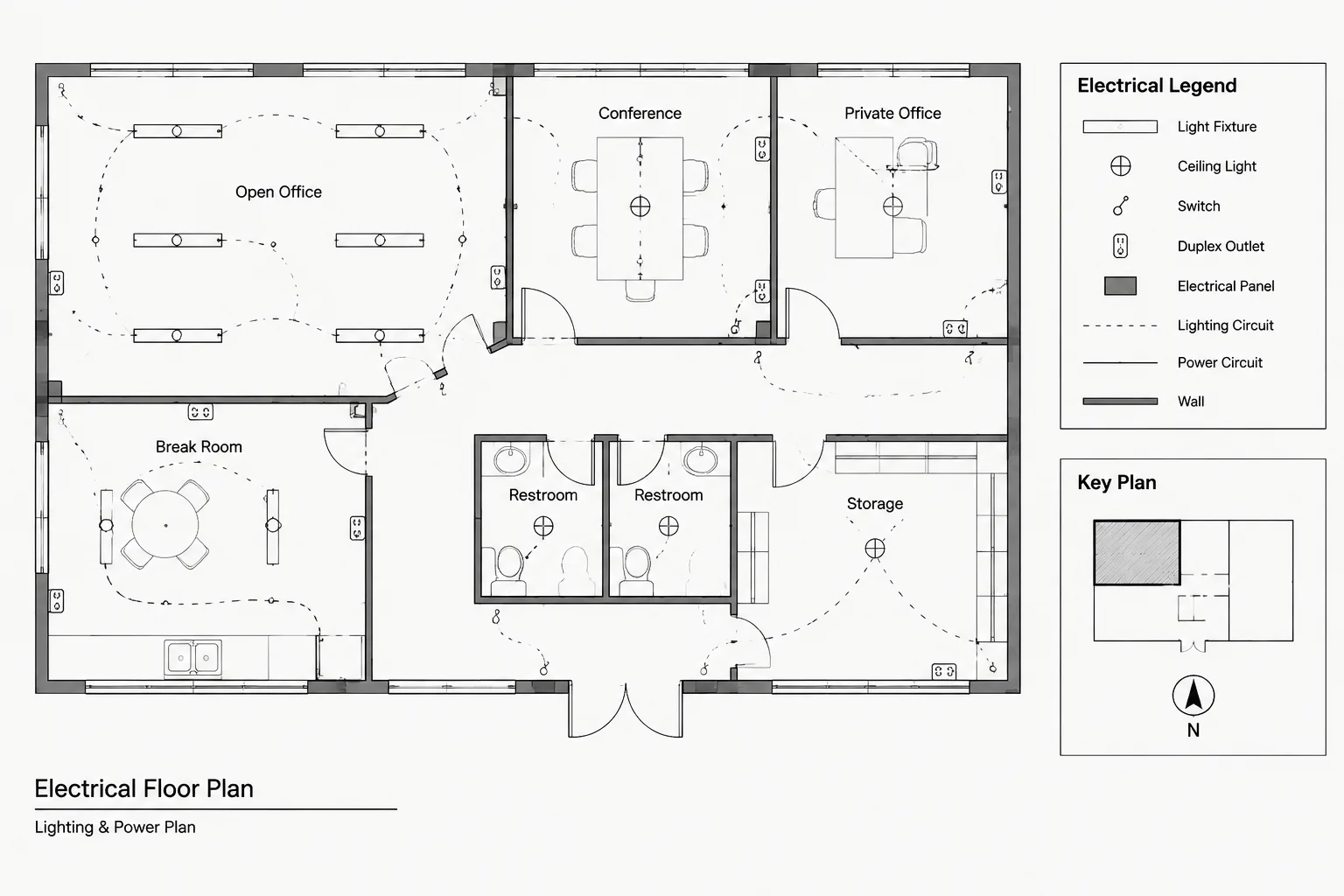
Electrical plan phasing in CAD requires a clear distinction between geographic work areas, construction sequence, and the status of individual electrical objects. When those concepts are documented separately but coordinated across the drawing set, readers can identify the applicable scope without interpreting overlapping graphics or conflicting notes.
This reference explains how boundaries, labels, layers, plans, diagrams, schedules, and sheet organization can work together. It focuses on drafting and documentation decisions rather than field procedures, allowing project-specific installation and safety requirements to remain under the control of the responsible professionals.
Electrical projects are often designed, permitted, bid, or constructed in multiple work stages. A building may remain occupied while selected rooms are renovated, utility work may precede interior construction, or separate bid packages may cover different areas. The electrical drawings must communicate those divisions without making users guess which devices, feeders, and notes belong to each stage.
Electrical plan phasing in CAD is more than drawing a dashed boundary around part of a floor plan. A coordinated phasing method connects plan graphics with demolition information, equipment status, single-line diagrams, schedules, details, and sheet organization. It also distinguishes construction phasing from electrical power phases, which is essential for avoiding ambiguous notes.
Construction phasing and electrical phases are different concepts
In electrical documentation, the word phase can refer either to a construction stage or to a characteristic of the electrical distribution system. A note such as “Phase A work” may therefore be misunderstood as a reference to an electrical phase conductor.
Use terminology that makes the intended meaning explicit. Depending on the project, suitable labels may include:
- Construction Phase
- Work Stage
- Bid Package
- Renovation Area
- Early Work
- Future Work
- Owner-Furnished Scope
The project team should select one vocabulary and use it consistently. If construction phase identifiers must be used, spell out “Construction Phase” in legends and prominent notes rather than relying on an isolated letter or number.
Decide what the phasing graphics need to communicate
Before creating layers or blocks, identify the questions the drawing must answer. A useful phasing plan generally indicates where a work stage applies, what electrical objects are included, how related work continues beyond the boundary, and where users can find further information.
A boundary alone rarely defines the complete scope. A feeder may originate outside the renovation area, a panel serving the area may remain in service, or a device inside the boundary may be excluded from the current package. Object-level status and system relationships must remain visible alongside the geographic division.
| Drawing element | Purpose | Coordination concern |
|---|---|---|
| Work-area boundary | Identifies the geographic limit of a stage or package | Must not conceal walls, devices, or room information |
| Area label | Names the applicable construction stage | Should match sheet titles, notes, and schedules |
| Object status | Distinguishes existing, removed, relocated, new, or future items | Should not depend on color alone |
| Continuation reference | Connects work crossing a boundary or sheet edge | Requires matching references at both ends |
| Key plan | Places a partial plan within the larger project | Should use the same area names as the main plans |
| Sequence note | Explains a dependency between stages | Should describe documentation intent without prescribing unsafe field procedures |
Create a clear CAD layer structure
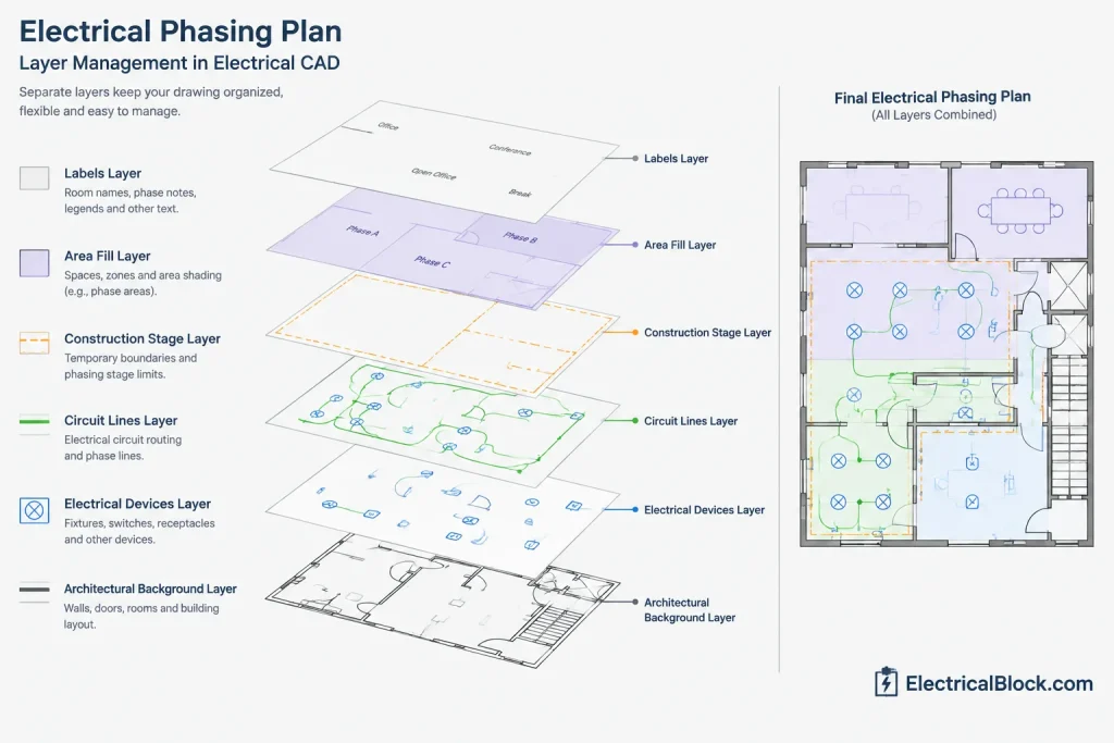
Phasing graphics should be separable from electrical design objects. Place boundaries, fills, labels, and key-plan highlights on dedicated layers rather than embedding them in device blocks or architectural backgrounds. This allows the graphics to be controlled by viewport and sheet type.
A practical layer breakdown may separate:
- Construction-stage boundaries
- Boundary labels and identifiers
- Area screening or transparent fills
- Temporary explanatory notes
- Key-plan highlights
- Package-specific continuation symbols
Layer names should follow the project’s established CAD convention. The important point is functional separation. A boundary should not share a layer with branch-circuit lines, and a phase fill should not be permanently attached to the architectural floor plan.
Test layer behavior in each viewport. A boundary useful on a phasing overview may be distracting on an enlarged equipment plan. Conversely, turning off all phasing information on a detailed plan can remove the context needed to understand its scope.
Draft boundaries without overpowering the plan
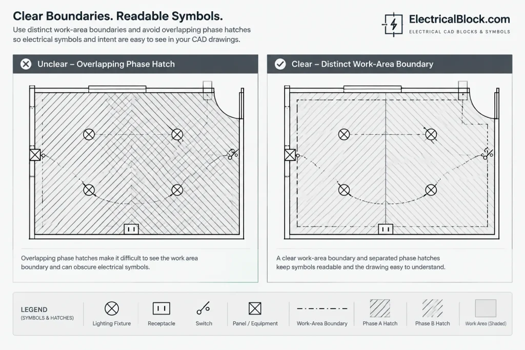
Work-area limits should be visually distinct but subordinate to the electrical information. Use a recognizable linetype, controlled lineweight, or restrained screening method. Avoid dense hatches that obscure circuit lines, device tags, ceiling information, or room names.
Draw the boundary as a closed and editable object where practical. A closed shape is easier to revise when room limits change and can support a separate background fill. Keep the boundary aligned with meaningful architectural features such as walls, grids, property limits, or room groups where those features define the scope.
Do not assume that a boundary line automatically assigns every object inside it to that construction stage. Add exceptions directly to the plan or identify them through status tags and notes. This is especially important when existing equipment remains operational within an active renovation area.
Place labels where they remain readable
Each bounded area should have a visible identifier. For large or irregular areas, repeat the label where necessary rather than forcing users to trace a long boundary. Keep labels out of dense device clusters and avoid placing them over panel names, feeder tags, or critical dimensions.
If several work stages overlap, do not rely on multiple competing hatches. Separate plans, viewport-specific graphics, or a concise diagram may communicate the relationship more clearly.
Coordinate phasing with demolition and new-work plans
Construction stage and object status are separate attributes. A device may belong to a later work stage while also being existing, new, relocated, or removed. Combining these concepts into one line style can produce an unreadable drawing.
Use the project’s normal demolition and new-work graphic conventions, then add the construction-stage boundary as another layer of information. The legend should explain both systems independently. For example, one legend section can define object status, while another defines work-area limits and stage labels.
When demolition and installation information appear on separate sheets, keep room names, equipment tags, and area identifiers consistent. A demolished device should not disappear from the documentation trail if its circuit, replacement, or associated equipment is discussed elsewhere.
Carry construction stages into diagrams and schedules
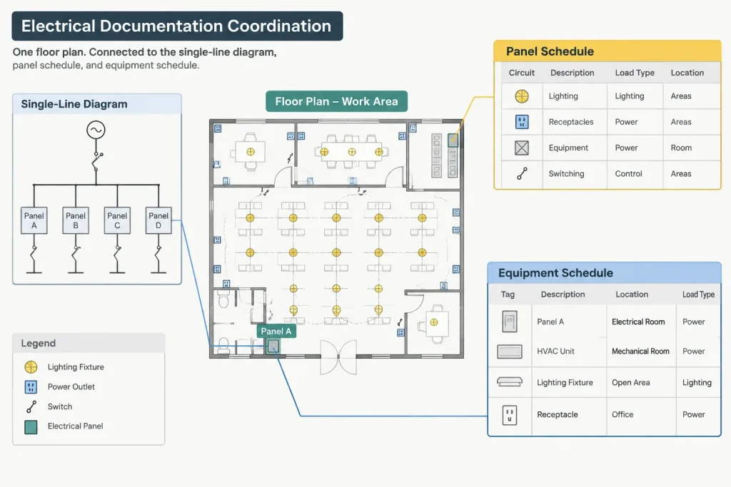
A floor-plan boundary cannot show every system dependency. Review related single-line diagrams, risers, panel schedules, equipment connection schedules, and cable or feeder schedules for phase-related information.
Useful coordination methods include:
- Adding a construction-stage field to equipment or feeder schedules when it serves a real documentation purpose
- Using keyed notes on a single-line diagram to identify staged modifications
- Showing future equipment with the project’s defined future-work convention
- Referencing the originating and destination sheets for work that crosses stage boundaries
- Keeping equipment names identical across plans, diagrams, and schedules
Avoid changing established equipment identifiers solely to encode construction sequence. Equipment tags usually need to remain stable throughout design, construction, record documentation, and facility use. Store stage information in a separate attribute, schedule column, or note when possible.
Use sheet organization to support the phasing strategy
Some projects are clearest when each construction stage has dedicated sheets. Others benefit from common base plans with stage-specific viewports or overlays. The choice depends on project complexity, overlap between stages, issue sequence, and the needs of reviewers.
Whichever structure is selected, make it visible in the sheet index and sheet titles. A user should be able to tell whether a plan represents all electrical work in an area, only one construction stage, or a combined reference view.
Key plans are particularly useful for partial-floor sheets. Highlight the represented area, label adjacent areas, and match the terminology used on the main plan. Keep the key plan diagrammatic; it should orient the reader rather than repeat every electrical object.
Manage changes without losing the phasing history
Phasing frequently changes as access, occupancy, funding, or construction packaging evolves. Treat boundaries and stage assignments as controlled design information rather than informal markups.
When a boundary changes, review more than the polyline. Check affected devices, keynote references, schedules, details, sheet titles, and continuation markers. Also examine whether previously issued work has moved into or out of the current package.
Do not use revision clouds as permanent work-area boundaries. A revision cloud identifies changed drawing content for a particular issue, while a construction-stage boundary communicates ongoing project scope. Keeping those graphics separate prevents confusion in later issues.
Quality-control checklist
- Construction-stage terminology is clearly distinguished from electrical phase terminology.
- Every work-area boundary has an understandable label or legend reference.
- Boundaries and fills do not obscure electrical or architectural information.
- Existing, removed, relocated, new, and future statuses remain independently identifiable.
- Equipment and circuit identifiers match across plans, schedules, and diagrams.
- Work crossing a boundary includes a clear continuation or cross-reference.
- Key plans and sheet titles use the same area names as the floor plans.
- Viewport layer controls do not accidentally hide necessary phasing information.
- Revised boundaries have been checked against notes, schedules, and related sheets.
- PDF plots remain understandable without depending on CAD layer access or display color.
Keep the phasing system simple enough to maintain
The best phasing graphics are not necessarily the most elaborate. They use a small, consistent set of boundaries, labels, object-status conventions, and references to explain how the drawing set is divided. If users need several overlapping hatches and a long decoding table to understand a room, separate sheets or diagrams may be the better solution.
CAD makes it easy to add visual categories, but each category must be maintained through every revision and plotted issue. A disciplined phasing system keeps the electrical design readable while giving reviewers, estimators, coordinators, and construction teams a reliable map of the documented work.
Establish a dependable source of phasing information
A coordinated drawing set should have an identifiable source for construction-stage names and area assignments. That source might be a phasing plan, a sheet organization strategy, or a controlled schedule used by the design team. Other views should repeat the approved terminology rather than creating local variations.
This approach makes revisions easier to trace. When an area name or package assignment changes, the drafting team can review every plan, diagram, schedule, detail, and reference that uses the same information. It also reduces the risk that a viewport label will disagree with a sheet title or equipment entry.
Review phasing as both graphics and data
Visual review should confirm that boundaries, fills, and labels remain legible in the plotted documents. A separate coordination review should confirm that the objects associated with each work stage are represented consistently throughout the drawing set.
- Compare area identifiers with sheet titles, key plans, and drawing indexes.
- Trace equipment and feeder references beyond the visible work-area boundary.
- Confirm that object status remains understandable when phasing layers are displayed.
- Check that referenced plans and diagrams use matching equipment identifiers.
- Review schedules for entries that could be mistaken as belonging to the wrong package.
These checks address different failure modes. A boundary may plot clearly while still enclosing an incorrectly assigned object, and a correctly assigned object may become difficult to interpret if screening hides its tag.
Prepare phasing graphics for downstream use
Recipients may review exported documents rather than the original CAD file. Phasing information should therefore remain understandable without access to layer controls, object properties, or a particular display configuration. Labels, line patterns, notes, and legends should carry the intended meaning in the issued format.
Editable CAD organization still matters for future revisions. Keeping stage graphics separate from design objects allows the team to update scope divisions without rebuilding device blocks or altering the architectural reference. The result is a phasing system that supports both immediate document reading and later drawing maintenance.
Frequently asked questions
Is a work-area boundary enough to define electrical scope?
No. A boundary identifies a geographic area, but electrical systems often extend beyond it. Equipment status, feeder relationships, continuation references, notes, schedules, and diagrams may also be needed to define the documented scope.
Should construction stages be built into electrical device blocks?
Usually, stage information is easier to manage as a separate property, layer, schedule field, or annotation. Embedding it permanently in a symbol can complicate reuse and may blur the distinction between the device identity and its construction assignment.
Can color be the only phasing indicator?
Color should not carry the meaning by itself. Issued documents may be printed, converted, or viewed under different display conditions. Pair color with labels, line patterns, boundaries, notes, or other conventions that remain readable in the final document.
How should work crossing a phasing boundary be shown?
Use coordinated continuation references or keyed notes that identify where the related information continues. Both ends of the reference should use matching terminology, and the associated equipment or circuit identifier should remain consistent.
Why should revision clouds and work-area boundaries remain separate?
They communicate different information. A revision cloud identifies changed drawing content for an issue, while a work-area boundary identifies ongoing construction scope. Using one graphic for both purposes can make later issues difficult to interpret.
When are separate phasing sheets helpful?
Separate sheets can improve clarity when work stages overlap, contain many exceptions, or require different combinations of notes and system information. The sheet titles, index, and key plans should make the organization apparent to the reader.












Leave a Reply
You must be logged in to post a comment.