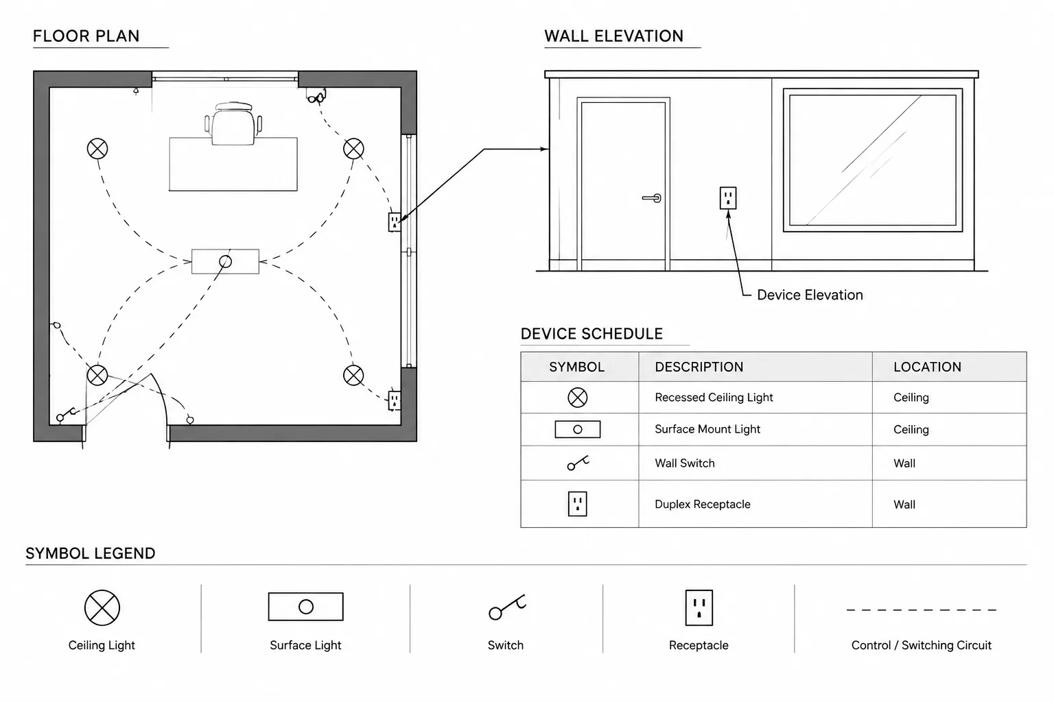
Electrical mounting height documentation must remain consistent wherever a device appears in the drawing set. This guide explains how CAD teams can organize typical requirements, identify exceptions, define measurement references, and coordinate information among plans, elevations, schedules, details, and notes.
The discussion focuses on drafting and document control rather than prescribing mounting criteria. Actual requirements should be confirmed from the applicable project documents, architectural conditions, equipment information, and governing requirements.
Electrical mounting height documentation appears simple until the same device is shown in several places. A receptacle may appear on a floor plan, a wall elevation, an equipment detail, and a device schedule. If those views use different reference points or conflicting notes, the construction documents become difficult to interpret.
A good CAD workflow does more than place a height beside every symbol. It establishes where mounting information belongs, how it is measured, which exceptions require graphic clarification, and how revisions are coordinated. The objective is a drawing set that communicates design intent without filling every plan with repetitive text.
What a mounting height note actually communicates
A mounting height designation should identify more than a vertical distance. The reader also needs to understand the object being located and the point on that object used for measurement. Depending on the device and project convention, the reference may be the centerline, top, bottom, face, operating component, outlet location, or another clearly defined point.
Do not assume that a generic abbreviation automatically explains the measurement basis. Define the convention in the drawing notes, legend, schedule, or typical mounting detail. Project requirements, applicable regulations, architectural criteria, equipment information, and accessibility considerations must be verified by the responsible design team.
Choose a hierarchy for the information
Before drafting, decide which drawing element governs the typical mounting information and which elements show exceptions. A practical hierarchy might use a general note or schedule for common conditions, plan notes for local exceptions, and elevations or details where vertical relationships need to be seen.
| Drawing location | Best use | Common risk |
|---|---|---|
| General notes | Project-wide measurement conventions and recurring requirements | Notes becoming too broad to describe special conditions |
| Symbol legend | Typical device descriptions and standard mounting references | Legend information being treated as applicable to every condition |
| Device schedule | Structured information by type or tag | Schedule entries conflicting with plan-specific notes |
| Floor plan | Location, orientation, grouping, and local exceptions | Excessive text obscuring walls and equipment |
| Wall elevation | Vertical alignment and relationships to architectural features | Elevation not matching the current plan or background |
| Detail | Repeated assemblies or unusual mounting conditions | Detail references being omitted from affected devices |
The hierarchy should be stated clearly. For example, a project may define schedule values as typical unless a tagged note or referenced detail indicates otherwise. The exact hierarchy is a project documentation decision; it should not be left for readers to infer.
Build mounting data into CAD symbols carefully
Attributes can make device blocks easier to coordinate, but only when the fields have a defined purpose. Useful attribute categories may include a device tag, type, mounting designation, reference note, served equipment identifier, or elevation/detail reference.
A block attribute should not become an isolated technical decision hidden inside a symbol. If a mounting value changes, the drafter must know whether the update also affects schedules, elevations, details, and specifications. Decide whether an attribute is the authoritative source, a displayed copy of schedule data, or merely a drafting aid.

Separate visible and management information
Not every attribute needs to plot. A device block may contain visible annotation for the plan and nonplotting fields used for selection, checking, or data extraction. Keeping these functions separate helps prevent long strings of metadata from overwhelming the drawing.
Use consistent property names across related block families. If receptacle, switch, control station, and communications blocks all store mounting information under unrelated field names, filtering and schedule extraction become unnecessarily difficult.
Draft typical conditions without over-annotating the plan
Repeating the same mounting note beside every symbol creates clutter and increases revision work. Instead, place recurring information in a controlled note, legend, or schedule. The floor plan can then concentrate on horizontal location and identify only meaningful exceptions.
Typical conditions still need to be discoverable. A reader should be able to move from the plan symbol to the legend or schedule without guessing. Keep symbol names, device tags, and schedule descriptions consistent. If multiple devices use similar graphics but different mounting conditions, differentiate them with a tag, modifier, or clearly documented symbol variation.
Show exceptions where context matters
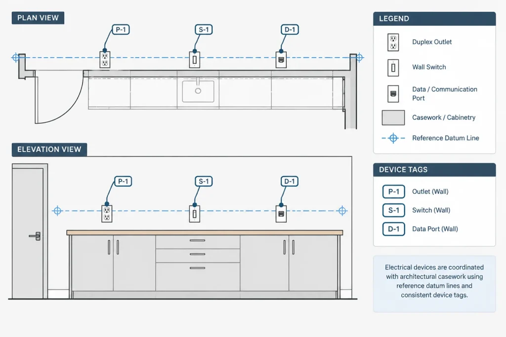
Some mounting conditions cannot be communicated reliably by a generic schedule entry. Devices associated with casework, counters, equipment, glazing, wall panels, headboards, furniture systems, or architectural features often require a contextual view.
Use an elevation or detail when the design depends on:
- Alignment with another electrical or low-voltage device.
- Relationship to a counter, shelf, cabinet, panel, or equipment enclosure.
- Placement above or below a finish transition.
- Coordination with doors, trim, glazing, signage, or wall protection.
- A group of devices arranged in a shared faceplate or organized cluster.
- A mounting reference that differs from the project-wide convention.
On the plan, add a restrained callout to the relevant elevation or detail. Avoid copying the same information into several views unless the project has a defined method for keeping those copies synchronized.
Coordinate reference datums and finish conditions
Vertical information is only useful when its datum is clear. Drawings may refer to a finished floor, structural level, ceiling, work surface, equipment base, or another project-defined reference. Identify that basis rather than relying on an unexplained number.
Renovation projects require particular care because existing floors, raised platforms, ramps, and finish changes may affect the intended reference. Equipment pads and architectural bases can also change where a device appears relative to the occupied surface. These conditions should be resolved through project coordination, not hidden in a generic CAD block.
Where finish thickness or construction tolerance is relevant, the electrical drawings should coordinate with the architectural documents and project requirements. The drafting team should not invent missing dimensions to make an elevation appear complete.
Manage mounting information with layers and annotation styles
Place mounting annotations on layers that support the project plotting and review workflow. Depending on the CAD standard, separate layers may be useful for device symbols, device tags, mounting notes, leaders, elevation references, and nonplotting coordination graphics.
Use a consistent text style, annotation size, leader format, and reading direction. Notes should remain legible at the intended sheet scale and should not cross device symbols, room names, door swings, or equipment outlines. When several devices share one requirement, a grouped note or bracketed callout may be clearer than multiple overlapping leaders.
Temporary coordination layers can be useful for highlighting devices that lack mounting data or require architectural confirmation. These layers should be reviewed and removed or set to nonplotting before issue.
Coordinate plans, elevations, and schedules
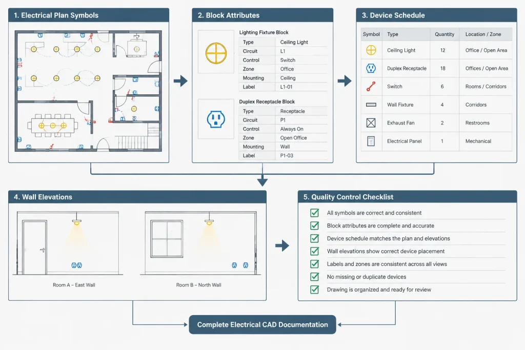
Cross-view consistency is the central quality-control task. A device shown on a wall elevation should have a corresponding plan location unless the drawing explicitly represents a typical condition. Its tag, type, orientation, and associated note should agree in every view.
A focused CAD review can include the following checks:
- Compare device tags on plans with the device or equipment schedule.
- Confirm that referenced elevations and details exist and use current identifiers.
- Search for local mounting notes that override typical schedule entries.
- Review duplicate devices created when plans and elevations were developed separately.
- Check mirrored rooms and repeated layouts for unintended annotation differences.
- Confirm that architectural casework, doors, furniture, and finish features reflect the current background.
- Identify devices that have neither a typical mounting category nor a documented exception.
Handle revisions without leaving conflicting notes
When a mounting condition changes, revise the source information first. Then review every dependent representation: blocks, schedules, notes, elevations, details, keynotes, and extracted data. Editing only the visible note nearest the device may leave a conflicting requirement elsewhere in the set.
Revision clouds and issue markers can identify changed drawing areas, but they do not replace coordination. If a typical condition changes, the revision may affect many devices even though only the legend or schedule is visibly edited. Use selection filters, attribute reports, or other available CAD review tools to find affected instances.
A practical documentation workflow
-
Define the convention. Establish the measurement basis, reference datum, abbreviation method, and information hierarchy.
-
Classify device types. Determine which devices use typical schedule information and which require project-specific review.
-
Prepare blocks and tags. Use consistent attributes and avoid embedding unverified technical requirements.
-
Draft the plans. Show horizontal locations and annotate only the exceptions that readers need at plan level.
-
Add contextual views. Create elevations or details for coordinated groups, equipment interfaces, and unusual architectural conditions.
-
Cross-check the set. Compare tags, notes, schedules, and references before issue.
-
Record unresolved items. Keep pending criteria visible in a controlled coordination list rather than disguising assumptions as final dimensions.
Keep design intent visible
Effective electrical mounting height documentation is not a collection of isolated numbers. It is a coordinated system connecting symbols, device types, reference datums, architectural context, schedules, and details. A clear hierarchy reduces plan clutter while making exceptions easy to find.
CAD blocks can support that system through consistent tags and attributes, but they cannot verify project requirements on their own. Final mounting criteria must be checked against the applicable project documents, equipment information, architectural conditions, and governing requirements before drawings are issued or used for construction.
Add ownership and status to the review process
Mounting information is easier to manage when the project team knows who supplies each requirement and whether that requirement is confirmed. The electrical drafter may record the information, while the underlying criterion may originate with the design team, architect, equipment consultant, owner, manufacturer, or another project participant.
A controlled coordination list can identify the device or tag, affected drawing area, required decision, responsible discipline, and current status. This keeps unresolved criteria from being converted into apparently final annotations merely to complete the graphic layout.
Review the information path, not only the plotted sheet
A plotted plan may look correct while its block data, schedule entry, or referenced elevation remains outdated. Quality control should therefore follow each mounting requirement from its governing source to every displayed or extracted representation.
- Source: Identify the note, schedule, approved criterion, or coordinated detail that establishes the requirement.
- Association: Confirm that the correct device type, tag, and block instance use that requirement.
- Display: Check that the plan, elevation, or detail communicates the intended reference point and datum.
- Exception: Verify that any local override is easy to find and does not silently conflict with typical information.
- Revision: Confirm that dependent views, schedules, attributes, and references were reviewed after a change.
Use clear status language for unresolved conditions
Pending information should be visibly different from an approved mounting designation. Teams may use a designated coordination field, review layer, status attribute, or controlled note convention. Whatever method is selected, it should be searchable and should not resemble final construction information when plotted.
Before issue, review temporary notes and coordination graphics deliberately. Resolve them, retain them under an approved project convention, or remove them as appropriate. Avoid replacing missing information with assumptions that cannot be traced to a verified project source.
Check repeated and mirrored layouts carefully
Copied rooms and mirrored arrangements can carry obsolete attributes, incorrectly oriented leaders, or exceptions that belonged only to the original location. Repeated layouts should be checked against current architectural backgrounds and room-specific requirements rather than accepted solely because their geometry matches.
Where many instances share a common condition, data extraction or selection filters can help locate inconsistent tags and attributes. Automated checking can reveal differences, but a reviewer must still determine whether each difference is intentional.
Frequently asked questions
Where should a typical electrical mounting height be documented?
The appropriate location depends on the project hierarchy. Recurring information is commonly managed through a general note, legend, schedule, or typical detail, while the plan identifies local exceptions. The drawings should state which source governs rather than requiring readers to infer precedence.
When is a wall elevation preferable to a plan note?
Use a wall elevation when vertical alignment or the relationship to casework, equipment, finishes, openings, or grouped devices is important to understanding the design. The plan should provide a clear reference to that elevation.
Should the mounting reference be measured to the centerline of every device?
Not automatically. The measurement point depends on the device and the project convention. The drawings should identify whether the reference applies to a centerline, edge, operating component, outlet location, or another defined point.
Can a CAD block attribute serve as the governing mounting requirement?
It can only do so when the project workflow explicitly defines it as the authoritative source. In other workflows, the attribute may simply display schedule data or support drafting checks. Its role must be documented to prevent conflicting edits.
How should conflicting plan and schedule information be handled?
Do not resolve the conflict by choosing an interpretation without verification. Check the documented hierarchy, identify the source of each entry, and refer the discrepancy to the responsible project team before issuing the drawings.
How should mounting information be handled when architectural conditions are uncertain?
Record the item as unresolved through the project’s coordination process. Avoid presenting an assumed value as final, and update the affected plans, elevations, schedules, and block data after the architectural condition is confirmed.
Do CAD symbols confirm accessibility or regulatory compliance?
No. Symbols and attributes organize drawing information, but they do not establish compliance by themselves. The responsible design team must verify mounting criteria against the applicable project and governing requirements.












Leave a Reply
You must be logged in to post a comment.