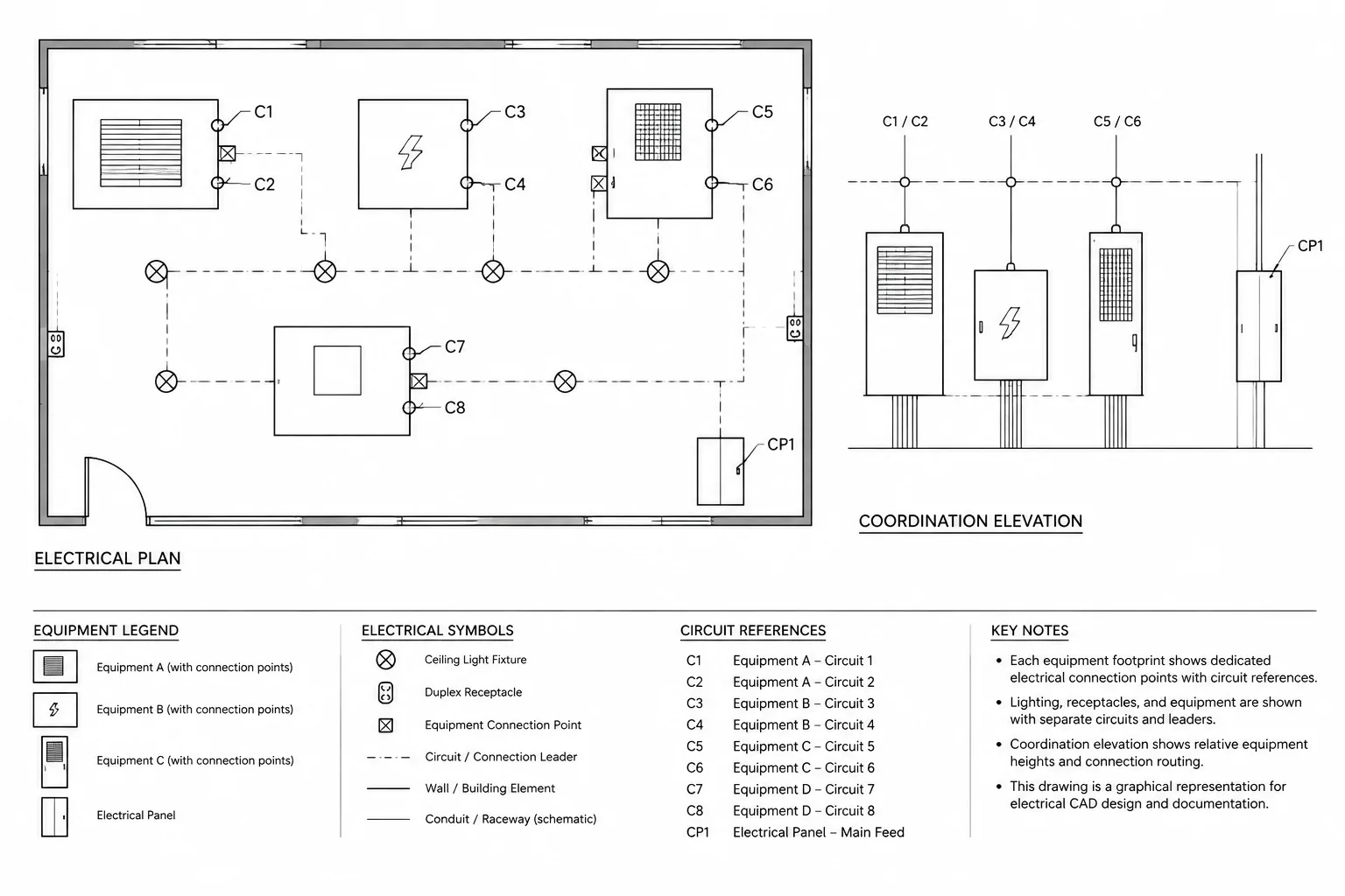
Electrical connection points in CAD should communicate more than a general relationship between a circuit and an equipment symbol. They should help drawing users identify the intended interface, understand which view controls its location, and recognize when further equipment coordination is required.
This drafting reference explains how to separate equipment footprints from electrical interfaces, select an appropriate graphic method, and maintain agreement among plans, elevations, details, schedules, and supporting diagrams. It is intended as a documentation workflow, not as installation guidance or a substitute for verified project information.
An equipment symbol can show where a unit sits without showing where its electrical connection actually belongs. This distinction matters for switchboards, mechanical equipment, kitchen appliances, packaged systems, specialty devices, and owner-furnished equipment. A centered plan symbol may be adequate for early layouts, but construction documents often need a more precise connection reference.
Documenting electrical connection points in CAD creates a consistent link between the equipment footprint, the branch circuit or feeder, the mounting condition, and the supporting schedules. The objective is not to design the internal wiring of the equipment. It is to communicate the intended interface clearly enough that plans, elevations, details, and equipment information do not contradict one another.
What Is an Electrical Connection Point?
A connection point is the documented location where an electrical service interfaces with equipment or a device assembly. Depending on the project, it may represent a receptacle, flexible connection, disconnect connection, terminal compartment, control interface, communications outlet, or another defined rough-in location.
The connection point is not necessarily the geometric center of the equipment block. It may be located at one end, on a particular face, above the equipment, below a work surface, or in an adjacent accessible area. Its final location may also depend on approved equipment information that is unavailable during early design.
A useful drawing distinguishes among three related items:
- Equipment footprint: The physical area occupied by the unit or assembly.
- Electrical device or connection: The outlet, junction point, disconnect, or other interface serving the equipment.
- Routing representation: The circuit line, feeder reference, raceway path, or continuation note leading to that interface.
Combining all three into one generic symbol can make a plan look simple, but it can hide important coordination differences.
Why Centered Equipment Symbols Cause Problems
Many CAD blocks use a convenient insertion point at the center of an equipment footprint. That insertion point helps with placement and rotation, but it should not automatically be treated as the electrical rough-in location.
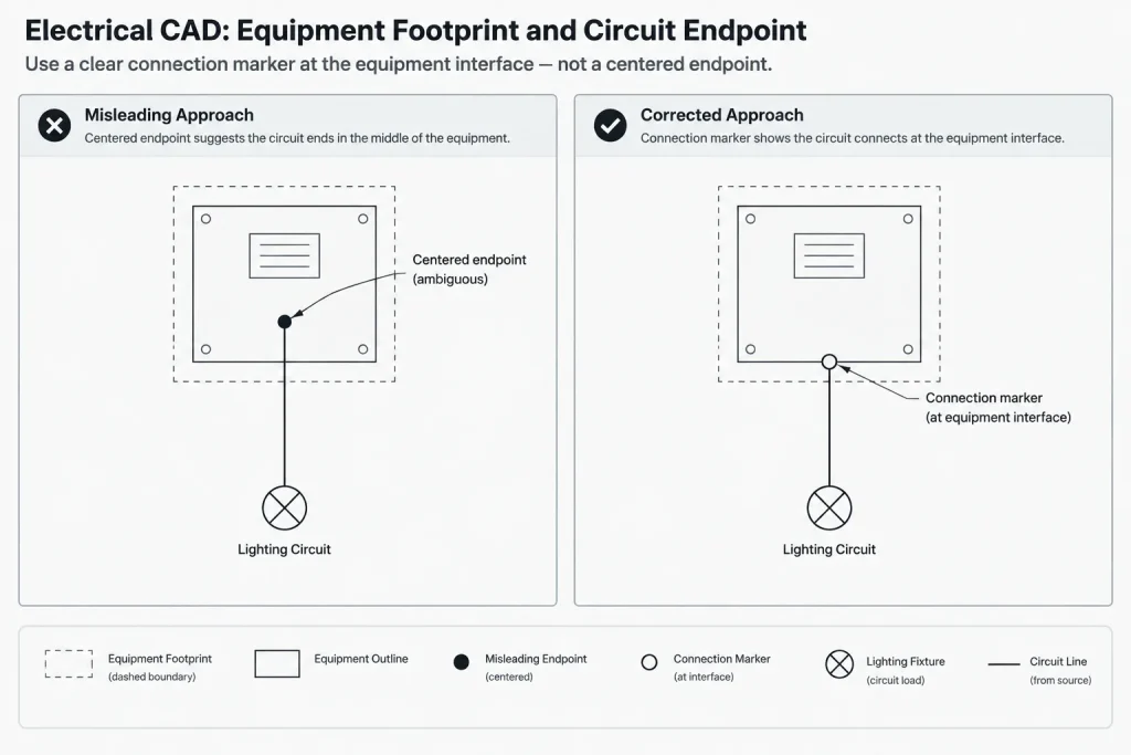
When a circuit line terminates at the block center, reviewers may be unable to determine whether the line represents a physical connection, a general association, or merely a drafting shortcut. The ambiguity becomes more significant when the equipment is large, has multiple services, or must be coordinated with walls, casework, piping, access panels, or structural supports.
Common consequences include:
- Plan locations that disagree with equipment elevations.
- Connection symbols concealed beneath equipment hatches or solid fills.
- Multiple utilities shown at the same point even though they enter different parts of the unit.
- Disconnects documented without a clear relationship to the equipment served.
- Schedules that list an equipment tag but provide no reliable plan reference.
- Early placeholder locations remaining in the issued drawing after equipment information changes.
Choose an Appropriate Graphic Method
The best representation depends on drawing scale, equipment complexity, and the certainty of the available information. A project may use more than one method, provided the legend and annotation rules remain consistent.
| Graphic method | Useful application | Coordination caution |
|---|---|---|
| Connection marker inside the footprint | Equipment with a known interface location visible at plan scale | Keep the marker readable above hatches and background geometry |
| Device symbol adjacent to equipment | Receptacles, disconnects, or connection boxes mounted nearby | Show the relationship without implying that the device is part of the equipment |
| Leader from equipment to a note | Early design or crowded layouts | State whether the indicated location is approximate or subject to verification |
| Keyed connection point tied to a detail | Assemblies needing mounting-height or interface clarification | Coordinate the key, detail reference, and equipment tag |
| Separate enlarged plan or elevation | Dense rooms, casework, production lines, or multi-service equipment | Prevent duplicate or conflicting dimensions between views |
A marker should not imply more precision than the project information supports. If the equipment selection is preliminary, an approximate zone with a clear verification note may be more accurate than a dimensioned point.
Build the CAD Block Around Separate Concepts
A reusable equipment block can include separate geometry for the footprint and the electrical interface. Keeping these concepts separate makes it easier to update a connection location without redrawing the equipment outline.
Use a Stable Equipment Base Point
Select a block base point that supports dependable placement, alignment, and rotation. A corner, centerline intersection, or another repeatable geometric reference may be more useful than the connection point itself. The electrical interface can then be represented by separate internal geometry or an attached symbol.
This approach prevents a revised connection location from shifting the entire equipment block. It also allows the same footprint to support different electrical configurations when properly identified and controlled.
Separate Display Geometry by Layer or Visibility
Equipment outlines, clearance graphics, connection markers, text, and hidden reference geometry should be independently controllable. A plan may need the footprint and connection marker, while an equipment layout may also need service zones or access references.

Do not depend solely on color to convey the distinction. Linework, symbols, tags, and plotted hierarchy should remain understandable in monochrome output.
Use Attributes Carefully
Block attributes can carry information such as equipment identification, connection type, circuit reference, source panel, or detail reference. Attributes are most useful when their purpose is defined consistently across the project.
Avoid placing unverified electrical characteristics into a generic library block. Project ratings, connection requirements, and interface details should come from the design documentation and verified equipment information, not from assumptions embedded in reusable CAD content.
Coordinate Plans, Elevations, and Details
A plan view is often insufficient when connection height or mounting face matters. The plan should lead the reader to an elevation or detail rather than attempting to compress every requirement into a crowded note.
For each important connection, compare the following:
- The equipment tag shown on the floor plan.
- The orientation of the equipment footprint.
- The face or compartment receiving the connection.
- The associated device, outlet, box, or disconnect symbol.
- The vertical location shown in an elevation or section.
- The circuit, feeder, or source reference.
- The equipment or connection schedule entry.
- Any note requiring verification with approved information.
If multiple drawing views show the same location, establish one controlling reference. For example, the plan may control horizontal placement while an elevation controls vertical placement. Repeating the same dimension in several views increases the chance that one copy will remain unchanged during a revision.
Document Multiple Services Without Creating a Symbol Cluster
Some equipment requires more than one documented electrical interface, such as normal power, backup power, controls, monitoring, or communications. Placing every symbol at the center of the footprint can produce an unreadable cluster.
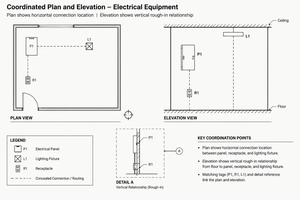
Use distinct connection markers, short leaders, or a keyed interface list. Each identifier should connect to a meaningful description in the legend, schedule, or detail. If other disciplines also provide services, coordinate the graphic language so that separate systems are not mistaken for duplicate electrical connections.
Where the exact entry arrangement is unknown, show an interface zone and identify the information that remains to be confirmed. This communicates design intent without presenting an assumed point as final.
Create a Connection-Point Review Workflow
A focused CAD review can find issues that are easy to miss during a general drawing check:
- Isolate equipment and connection layers. Confirm that every scheduled item requiring an electrical interface has a corresponding plan reference.
- Review block orientation. Check whether rotating or mirroring the equipment also moved the connection marker to the intended side.
- Compare architectural and equipment backgrounds. Look for connections inside walls, beneath inaccessible surfaces, or in conflict with doors and casework.
- Trace source references. Verify that circuit and feeder identifiers agree with the applicable schedules and diagrams.
- Check enlarged views. Confirm that the equipment tag and connection location match the overall plan.
- Plot a review sheet. Inspect symbol visibility, leader crossings, masking, and text at the intended output scale.
- Track unresolved information. Maintain visible coordination notes or a project issue log instead of relying on memory.
Use Notes That Describe Status Clearly
Notes should tell the reader whether a connection location is coordinated, approximate, diagrammatic, or pending verified equipment information. Avoid broad language that shifts every coordination decision to the field without identifying what must be checked.
A useful note can identify the equipment tag, the interface being located, the controlling drawing view, and the source of pending confirmation. Project teams should adapt note wording to their documentation practices and contractual responsibilities.
Final Drafting Principle
An electrical equipment block and an electrical connection point answer different questions. The footprint shows where the equipment is located; the connection point shows where the electrical documentation interfaces with it. Treating these as separate but coordinated CAD objects improves plan readability, revision control, and cross-discipline coordination.
Before issuing a drawing, verify connection locations against current project information, related views, and applicable schedules. Library blocks are starting points for documentation, not proof that a particular connection arrangement is correct for a real installation.
Add a Connection Register to the Documentation Workflow
Projects with many equipment interfaces can benefit from a simple connection register maintained alongside the CAD review process. The register does not replace equipment or circuit schedules. Its purpose is to track whether each documented interface has a coordinated location and a reliable supporting reference.
Useful register fields may include:
- Equipment tag: The identifier used consistently across plans, schedules, and details.
- Connection identifier: The marker or key assigned to the documented interface.
- Interface description: A concise description of the outlet, connection box, disconnect relationship, control interface, or other rough-in reference.
- Controlling view: The plan, elevation, section, or detail responsible for location information.
- Information source: The schedule, approved equipment information, consultant drawing, or coordination record supporting the location.
- Coordination status: A clear indication that the point is preliminary, pending confirmation, or coordinated with current information.
- Review note: A brief record of conflicts, orientation concerns, or unresolved dependencies.
This type of register is especially helpful when equipment changes occur after symbols have already been placed. It gives reviewers a way to distinguish verified updates from connection points that still reflect an earlier layout.
Control Revisions at the Interface, Not Only at the Footprint
An equipment block may remain in the same location while its electrical interface moves to another face or compartment. A revision review that compares only equipment footprints can therefore miss a meaningful rough-in change.
When project information is updated, review the connection marker, associated device, leader, source reference, controlling detail, and schedule entry as a coordinated group. If an external reference or background changes, confirm that the apparent connection location did not shift because of altered geometry, clipping, masking, or equipment orientation.
Revision clouds and issue notes should identify the drawing information that changed without implying that unverified equipment requirements have been resolved. The current project documents and approved equipment information remain the basis for final coordination.
Frequently Asked Questions
Is a CAD block insertion point the same as an electrical connection point?
Not necessarily. The insertion point is primarily a block-placement reference. An electrical connection point represents the documented interface serving the equipment and may be located elsewhere within or near the footprint.
What should a drawing show when the exact connection location is unknown?
Use an approximate interface zone, keyed note, or other clearly qualified graphic method. Identify the information that remains to be verified rather than presenting an assumed point as final.
Should a circuit line terminate at the center of an equipment symbol?
It may indicate a general association if the project drafting convention makes that meaning clear. When the physical interface matters, use a separate marker, device symbol, leader, or detail reference so the line endpoint is not mistaken for a precise rough-in location.
How can connection markers remain correct when equipment blocks are rotated or mirrored?
Keep the equipment footprint and interface geometry independently reviewable. Test the block in the orientations expected on the project, and confirm that the marker still corresponds to the intended equipment face or compartment after placement changes.
Which drawing view should control a connection location?
The project should establish a consistent hierarchy. A plan may control horizontal placement while an elevation or detail communicates vertical placement and mounting relationships. Avoid repeating controlling information in several views unless every instance is managed together.
What information belongs in a reusable equipment block?
A reusable block may include stable footprint geometry, identification fields, connection markers, and controlled display elements. Do not embed unverified project ratings or assumed interface requirements in a generic library block.










Leave a Reply
You must be logged in to post a comment.