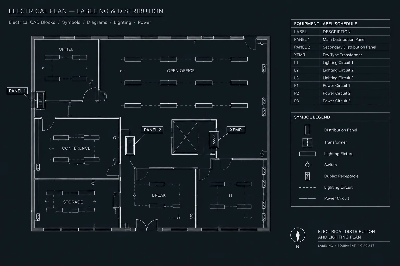
Electrical labeling plans in CAD provide a coordinated documentation layer between equipment graphics, project identifiers, label schedules, and installation-facing notes. Effective plans make each identification requirement traceable while preserving the readability of the underlying electrical layout.
The guidance below focuses on organizing label data, distinguishing project annotations from physical markings, and maintaining consistent equipment names across plans, diagrams, schedules, details, and renovation documents.
An electrical labeling plan documents where identification is required and connects each physical label to information elsewhere in the drawing set. It can cover equipment names, source references, panel identifiers, disconnect labels, control enclosures, distribution equipment, and other project-specific markings.
This drawing is not simply a floor plan filled with text. A useful labeling plan separates drafting identifiers from labels intended for installation, establishes a repeatable tagging system, and directs readers to schedules or details containing the complete wording. The result should help designers, reviewers, fabricators, and field teams understand what is being identified without making the base plan unreadable.
Label content and placement requirements vary by project, equipment type, governing criteria, owner preferences, and applicable regulations. CAD blocks and example details should therefore be treated as documentation resources rather than automatically approved project solutions.
Distinguish Drawing Tags from Physical Labels
One of the most common sources of confusion is using the same-looking annotation for several different purposes. An equipment tag shown on a plan may be only a drawing reference, while a nameplate callout may represent text that must appear on the installed equipment.
Electrical labeling plans commonly use several identification categories:
- Drawing tags: Short identifiers used to connect equipment on a plan to a schedule, one-line diagram, detail, or specification.
- Equipment identifiers: Project names assigned to panelboards, transformers, switchboards, control panels, disconnects, and similar assets.
- Source references: Information identifying an upstream source, associated panel, feeder, circuit, or system relationship.
- Operational labels: Text describing a function, control purpose, operating relationship, or equipment served.
- Safety or warning labels: Project-required markings that should be coordinated with the applicable design criteria rather than improvised by the drafter.
- Manufacturer nameplate information: Product-specific data supplied with equipment and generally not recreated as though it were a designer-authored field label.
A clear legend should explain which symbols indicate drawing references and which callouts represent installed labels. Different border styles, prefixes, leaders, or annotation layers can make this distinction visible.
Decide Whether a Dedicated Labeling Plan Is Needed
Not every project requires a separate labeling sheet. A small drawing set may coordinate labels through equipment schedules, keynotes, and typical details. A dedicated plan becomes more useful when there are many pieces of equipment, multiple power sources, repeated room layouts, owner-specific asset names, or extensive renovation work.

A labeling plan can also function as a focused review view. By suppressing unrelated circuiting, dimensions, and architectural detail, the drafter can inspect identification coverage without searching through several crowded power plans.
Build a Practical CAD Layer Structure
Labeling information should be separable from normal equipment graphics. This allows it to appear on a dedicated sheet, within a coordination viewport, or as an overlay during quality control.
A project layer scheme may separate:
- Installed-label symbols and outlines
- Label text and tag values
- Leaders and location callouts
- Existing labels to remain
- New labels
- Labels to be removed or replaced
- Review comments or temporary coordination notes
Layer names should follow the project CAD standard. More layers are not automatically better; the goal is enough separation to control visibility and status without making editing unnecessarily complicated.
Use Blocks for Repeated Label Types
A block can represent a generic nameplate, source label, equipment identification label, or keyed labeling note. Useful attributes may include the equipment ID, label type, status, schedule reference, and drawing note.
Keep lengthy wording out of small plan symbols. A compact attribute such as a label key is easier to manage when it refers to a schedule containing the full text. If attributes will be extracted, their names and expected values should be standardized before many blocks are placed.
Create a Label Schedule
A label schedule centralizes wording and reduces repeated text. It also gives reviewers a convenient place to compare labels that perform similar functions.
| Field | Documentation purpose |
|---|---|
| Label key | Connects the plan callout to the schedule entry. |
| Equipment ID | Identifies the associated equipment or asset. |
| Label category | Distinguishes identification, source, operational, warning, or other project-defined types. |
| Required wording | Records the intended label text or points to an approved note. |
| Drawing location | References the plan, elevation, diagram, or detail where the label applies. |
| Status | Indicates whether the item is new, existing, relocated, retained, or replaced. |
| Remarks | Captures coordination information that does not belong in the label wording. |
Do not populate missing technical information by assumption. Where final data depends on selected equipment, source assignments, studies, or contractor coordination, use a clearly defined placeholder and track it for resolution.
Draft the Plan Without Obscuring Equipment
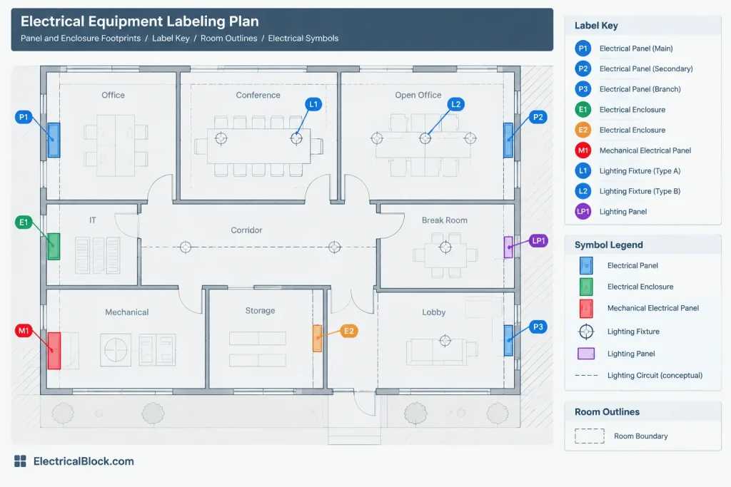
Start with the coordinated electrical plan background and display only the information needed to locate equipment. Architectural walls, room names, doors, and major fixed elements may be helpful, while dense hatch patterns and unrelated services can usually be screened or hidden.
Place each label marker near its associated equipment, but avoid covering disconnect symbols, connection points, door swings, or access areas. Use short leaders where the relationship would otherwise be ambiguous. Repeated labels in a lineup may be organized along a common annotation band rather than scattered across the equipment graphics.
For closely arranged equipment, an elevation or enlarged plan may communicate label placement better than the overall floor plan. The main plan can then carry a callout directing readers to that view.
Coordinate Labels Across the Drawing Set
Equipment names should remain consistent across plans, one-line diagrams, schedules, elevations, details, and control drawings. Small naming differences can create uncertainty over whether drawings refer to the same asset.
During coordination, compare:
- Equipment IDs on plans against the equipment schedule
- Panel and distribution names against the one-line diagram
- Source references against feeder and circuit documentation
- Disconnect identifiers against the equipment served
- Control enclosure names against schematics and interconnection diagrams
- Existing and new status against demolition and renovation drawings
If another discipline names the same equipment differently, resolve the naming convention rather than carrying competing identifiers into the issue set. Where both an electrical ID and an owner asset ID are necessary, provide separate fields and explain their use.
Document Label Location with Plans and Elevations
A plan can identify which equipment receives a label, but it may not clearly communicate where the label belongs on the equipment. Typical elevations can show the intended relationship between labels, handles, meters, displays, vents, and enclosure sections without pretending to represent a specific product configuration.

Use location language carefully. Phrases such as “typical location” or “coordinate with approved equipment arrangement” communicate design intent while acknowledging that final geometry may depend on the selected product. Avoid drawing a precise face layout unless verified equipment information supports it.
Handle Renovation and Existing Labels
Renovation projects require status clarity. Existing labels may be retained, replaced, supplemented, or removed because equipment is being renamed or its source is changing.
Do not rely only on color to express status, since drawings may be printed in monochrome. Combine layers with line patterns, symbols, prefixes, or status columns. If an existing identifier changes, record both the previous and new designation in a controlled schedule or mapping table so reviewers can follow the transition.
Quality-Control Checklist
Before issuing an electrical labeling plan, perform a focused review:
- Confirm that every label marker points to a specific item.
- Check that drawing tags and installed labels are graphically distinct.
- Compare equipment IDs across plans, schedules, diagrams, and details.
- Verify that label keys are unique and appear in the schedule.
- Remove unresolved drafting notes from plotted deliverables.
- Identify placeholders that still require verified project information.
- Check existing, new, removed, and replaced statuses.
- Review crowded areas at the intended plotted scale.
- Confirm that leaders do not point to adjacent equipment accidentally.
- Verify that required label wording has been reviewed under the project’s governing criteria.
Make the Labeling Plan Maintainable
The best labeling plan is not merely complete at one issue milestone; it is structured so changes can be managed. Use consistent block definitions, controlled attributes, a centralized schedule, and equipment names that match the rest of the drawing set.
When equipment is renamed or its source changes, update the identifier at its controlled source and then review every dependent drawing. A final comparison between the labeling plan, one-line diagram, schedules, and equipment layouts can catch inconsistencies before they become field questions.
Control Label Data at Its Authoritative Source
A maintainable labeling workflow depends on knowing which document or data field governs each item. The plan may show where a label applies, while a schedule controls its wording and an equipment schedule controls the associated asset name. Defining these responsibilities prevents several drawings from becoming competing sources of information.
When a change occurs, revise the authoritative source first and then review every dependent reference. Editing an isolated plan annotation without checking diagrams, schedules, and details can leave conflicting identifiers in the drawing set.
Separate Identity, Wording, and Location
Label records are easier to manage when they distinguish the identity of the equipment, the wording intended for the physical marking, and the drawing location of that marking. These fields may be related, but they are not interchangeable. An equipment ID can remain stable even when label wording or placement changes.
This separation is particularly helpful when owner asset names, electrical designations, and manufacturer information appear near the same equipment. Each should have a defined purpose and should not be merged into an ambiguous annotation.
Use Attribute Data for Coordination Checks
Consistent block attributes can support schedule generation and comparison, but extraction is useful only when attribute values follow controlled conventions. Variations in spelling, punctuation, status terms, or equipment naming can create duplicate-looking records and weaken automated checks.
Before relying on extracted data, review blocks for missing values, outdated definitions, manually overridden text, and labels that have lost their equipment association. Visual review remains necessary because a complete data record does not prove that a leader points to the correct object or that the annotation is readable on the plotted sheet.
Plan for Revisions and Drawing Handoffs
Labeling information often changes as equipment selections, source assignments, and owner naming decisions are finalized. Revision tracking should identify which records changed and whether related plans, diagrams, schedules, and elevations were reviewed.
For drawing handoffs, retain understandable layer names, block definitions, attribute descriptions, and status conventions. Remove temporary coordination notes from issue views while preserving unresolved items in an appropriate tracking process. This gives the next editor a clear distinction between approved drawing content and information still awaiting verification.
Review Both Data and Graphics
A complete quality review should examine the label data and its graphical presentation. Data checks find missing keys, inconsistent names, and unresolved placeholders. Graphic checks reveal crossed leaders, hidden markers, overlapping text, incorrect status symbols, and callouts that appear to point to neighboring equipment.
Review the plan using the same visibility settings and plotting conditions intended for issue. A label that is clear in the working model may become ambiguous after backgrounds are screened, layers are hidden, or the sheet is printed in monochrome.
Frequently Asked Questions
What is the difference between an equipment ID, a nameplate, and a field label?
An equipment ID is a project-controlled identifier used to coordinate drawings and schedules. A manufacturer nameplate contains product information supplied with the equipment. A field label is a project-required physical marking associated with installation, identification, operation, source information, or another documented purpose. Project legends should define how these terms are used.
Should full label wording appear on the CAD plan?
Not necessarily. Compact label keys can keep the plan readable while directing users to a schedule or detail containing the controlled wording. Full text may be appropriate where it remains clear and does not duplicate information that is better maintained elsewhere.
Can the same CAD block represent every label category?
A shared block framework may be practical if its attributes and visible graphics clearly distinguish label categories. However, using an identical appearance for drawing references, installed labels, and temporary coordination notes can cause confusion. The block strategy should support clear plotting and reliable data extraction.
How should unresolved label information be shown?
Use a defined placeholder or status that is visibly different from approved wording, and track the unresolved item outside the final label text. Do not guess source names, equipment data, warning language, or other project-specific information.
When is an elevation preferable to a plan callout?
An elevation is useful when the face of the equipment contains several sections, controls, displays, handles, or other features that affect label placement. The elevation should communicate design intent without implying an unverified product arrangement.
How can labeling revisions be checked efficiently?
Start with the controlled equipment and label records, identify changed IDs or wording, and compare those changes against plans, one-line diagrams, schedules, details, and renovation status documents. Finish with a plotted graphic review to confirm that callouts remain readable and correctly associated.












Leave a Reply
You must be logged in to post a comment.