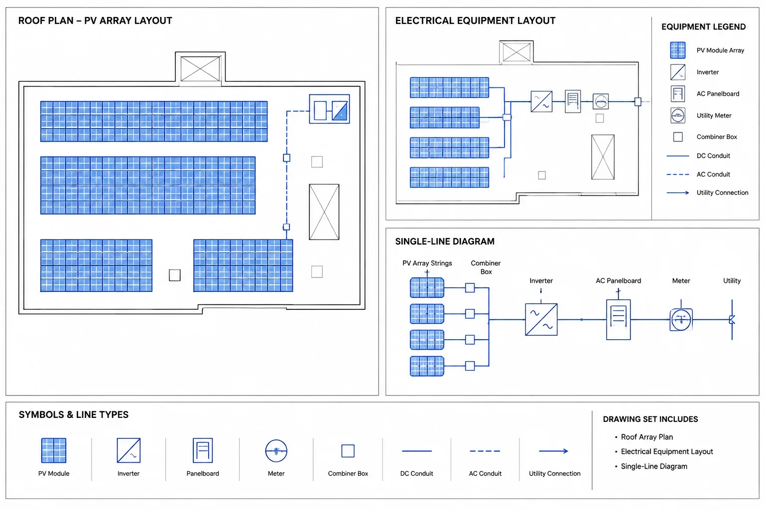
Solar PV drawing sets in CAD require more than a well-drafted array plan. The physical layout, equipment locations, electrical connections, route references, schedules, and identifiers must describe the same system across every sheet.
This drafting reference explains how to divide information among plans, diagrams, elevations, details, and schedules while maintaining traceable relationships between them. It is intended for CAD coordination and documentation review, not system sizing or field installation.
A solar photovoltaic drawing set must connect physical locations with electrical relationships. The roof or site plan shows where modules and equipment are placed, while the single-line diagram explains how the system connects electrically. Equipment elevations, schedules, details, and labeling notes add information that cannot be communicated clearly on one plan.
Good CAD documentation keeps these views synchronized without forcing every piece of information onto every sheet. This guide describes a practical drafting workflow for preparing and reviewing a solar PV drawing set. It focuses on drawing organization and coordination rather than system sizing, installation, or energized electrical work.
Start with the required drawing relationships
Before placing module blocks, identify the views needed to describe the project. The exact deliverables depend on the project scope, local review process, utility requirements, and applicable regulations. A typical set may include:
- A site or roof plan showing the array and relevant building context
- An enlarged array layout with module grouping and orientation
- An electrical equipment plan showing inverters, disconnecting equipment, panels, and related components
- A single-line diagram showing the electrical path from the array to the connection point
- Equipment elevations or mounting diagrams where spatial relationships need clarification
- Schedules for modules, strings, inverters, conductors, raceways, or equipment
- Installation details and project-specific notes
- A labeling or identification plan when required for coordination
Create a simple sheet map before drafting. For each drawing, define what it controls and which other views reference it. This prevents duplicated information from developing independently.
Build the array plan from a controlled background
The array plan should use a verified architectural, structural, civil, or survey background as appropriate. Keep the source background attached as an external reference when the project workflow permits. Avoid tracing building edges into the electrical file unless there is a clear reason, because traced geometry can become outdated without being noticed.
Show enough context to establish the array location. Depending on the installation, useful background elements may include roof edges, parapets, ridges, valleys, access points, mechanical equipment, skylights, drainage features, property boundaries, parking areas, or grade-level structures. The electrical drawing should not imply that these features have been independently verified when they come from another discipline.
Use module blocks consistently
A module block should have a predictable insertion point, orientation, and visible extent. If several module types occur, use distinct type identifiers rather than relying only on minor graphical differences. Attributes can store information such as a module type, array group, string assignment, or status, but only when those fields are maintained through a controlled workflow.
Do not assume that a generic module block represents actual equipment dimensions. Replace or adjust preliminary blocks after verified project information becomes available. The drawing should clearly distinguish conceptual layouts from coordinated equipment layouts.

Separate physical grouping from electrical grouping
Rows and subarrays are physical arrangements. Strings, source circuits, or inverter groupings describe electrical relationships. These groupings may overlap, but they are not automatically identical.
Use different graphical methods for each purpose. For example, a boundary or area label can identify a physical array, while concise tags can identify electrical groupings. Avoid running dense circuit lines through every module if tags and a schedule can communicate the same intent more clearly.
Draft the equipment plan as a coordination view
The equipment plan should locate major electrical components in relation to walls, roofs, service areas, paths, and other building systems. Depending on the design, the plan may show inverters, combiners, disconnecting equipment, switchboards, panelboards, transformers, meters, monitoring components, energy storage equipment, and utility interface equipment.
Use equipment footprints based on verified project data when available. Generic CAD blocks are useful during early planning, but they should not be treated as manufacturer-confirmed dimensions. Include a note or status convention when equipment is schematic, preliminary, or subject to final selection.
Where plan geometry cannot communicate the arrangement adequately, add an elevation or section. This is especially useful for wall-mounted equipment groups, stacked components, rooftop supports, and locations with architectural or mechanical conflicts.
Show routes without overstating installation detail
Raceway and cable routes on a plan can represent design intent rather than exact installation geometry. Establish a graphic convention for each level of certainty:
- Solid routing for coordinated paths
- Dashed routing for concealed, overhead, below-grade, or diagrammatic paths, as defined by the legend
- Route tags that connect plan segments to a conduit or cable schedule
- Continuation references where a route moves between plans, levels, or details
State the meaning of the convention in the legend. A dashed line has no universal project meaning unless the drawing defines it.
Construct the single-line diagram around the power path
The single-line diagram should present the electrical sequence clearly, not imitate the geographic plan. Organize it so a reviewer can follow the system from the PV source through conversion and distribution equipment to the point of connection.
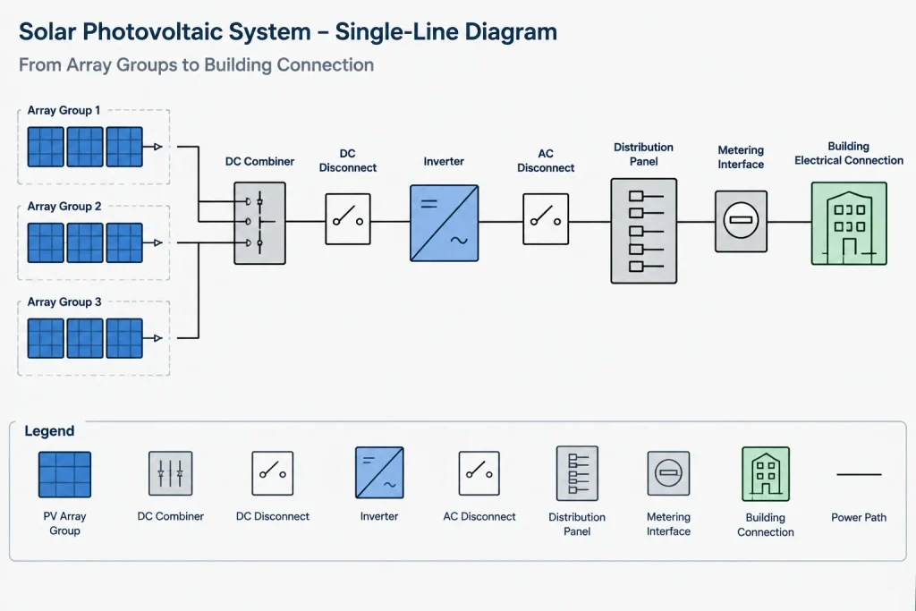
Keep related components aligned and leave room for identifiers and design data. Typical diagram elements may include array or string references, combiner equipment, inverters, disconnecting equipment, overcurrent protective devices, distribution equipment, metering interfaces, transformers, and the connection to the existing electrical system.
Each diagram symbol should carry an equipment identifier that matches the plan and schedules. If an inverter is identified one way on the roof plan and another way on the single-line diagram, the reader cannot reliably determine whether the views describe the same device.
Avoid turning the one-line into a plan
Physical distance and routing bends usually do not belong on the single-line diagram. Use the one-line for connectivity and the plan for location. Where routing affects documentation, connect the two views with feeder, cable, or raceway tags.
Likewise, avoid adding detailed internal circuitry unless it is necessary to explain the project interface. Manufacturer diagrams may contain information that is useful for product documentation but excessive for a project-level single-line diagram.
Coordinate tags and schedules
A stable identification system is the foundation of the drawing set. Use unique tags for major equipment and consistent identifiers for arrays, subarrays, strings, feeders, and raceways where those items must be tracked.
| Information | Primary drawing location | Coordination reference |
|---|---|---|
| Module placement | Array or roof plan | Module schedule and array tags |
| Equipment location | Equipment plan | Single-line diagram and equipment schedule |
| Electrical connectivity | Single-line diagram | Plan equipment tags |
| Raceway or cable path | Plan or routing diagram | Route schedule and continuation references |
| Mounting relationship | Elevation, section, or detail | Plan callout and equipment identifier |
| Required identification | Label schedule or notes | Equipment and location tags |
Where possible, generate repeated schedule information from maintained block attributes or project data. Automated extraction can reduce retyping, but it does not replace checking. Empty attributes, duplicate identifiers, exploded blocks, and copied equipment can all produce misleading schedules.
Organize layers by drawing function
A practical layer structure should let the drafter isolate the array, equipment, routing, annotations, boundaries, and reference geometry. Separate layers are also useful for existing work, new work, future provisions, and demolition when those statuses are part of the project.
Avoid creating a layer for every individual string or module unless the project has a specific management need. Excessive layers make visibility control difficult. Use blocks, attributes, tags, and schedules for object-level information, and reserve layers for broad graphical control.

Check layer visibility in every viewport. A module identifier that appears in model space but is frozen in a plotted viewport can break the connection between the plan and the schedule.
Plan labels and notes as coordinated data
PV projects may require equipment markings, directory information, warning labels, or identification at specific locations. The applicable wording, placement, appearance, and review requirements must be verified for the project and jurisdiction. Do not copy label content from an unrelated drawing set and assume it remains valid.
In CAD, a label schedule can include a label identifier, intended location, related equipment tag, and project-specific wording. On plans or elevations, show the identifier at the intended location rather than placing long text repeatedly. This makes later wording revisions easier to manage.
Run a cross-drawing quality-control review
Review the set by following each system path in both directions. Start at an array group and trace it through the plan tags, schedules, single-line diagram, equipment plan, and connection point. Then begin at the connection point and work back toward the modules.
A focused CAD review should check:
- Every major equipment tag is unique and appears in the expected views
- Array and electrical group identifiers agree between plans and diagrams
- Equipment shown on the one-line can be located on a plan or referenced detail
- Continuation symbols identify a clear destination
- Schedules do not contain orphaned or duplicate entries
- Generic blocks have not been mistaken for verified equipment geometry
- Background references are current and correctly aligned
- Legends define project-specific symbols, line types, and status graphics
- Viewport layer settings do not hide essential tags or routes
- Revisions are reflected across every affected drawing and schedule
Keep design intent visible
A strong solar PV drawing set does more than display modules on a roof. It creates a traceable connection between physical layout, electrical topology, equipment identification, and supporting documentation. CAD blocks contribute reusable geometry, but tags, schedules, references, and disciplined review turn that geometry into a coordinated drawing set.
Before issue, verify project requirements with the responsible design professionals, equipment information, serving utility, reviewing authority, and applicable regulations. The CAD set should communicate verified design intent without implying that preliminary symbols or generic details are approved for construction.
Manage revisions by following drawing dependencies
A revision to one PV object can affect several parts of the drawing set. Instead of reviewing only the sheet where a change originated, identify every view that depends on the revised information.
- Module or array changes: Review the array plan, grouping identifiers, schedules, and related diagram references.
- Equipment substitutions: Recheck the plan footprint, equipment tag, elevation, schedule entry, and single-line symbol.
- Route changes: Review route tags, continuation references, associated schedules, and any affected details.
- Identifier changes: Search the complete drawing package for matching tags, callouts, notes, and schedule records.
- Background updates: Confirm reference alignment and review the revised area for spatial conflicts.
A simple revision-impact record can identify the changed object, the drawing that controls it, dependent views, and its current verification status. This creates a review trail without duplicating design data throughout the CAD files.
Prepare the CAD package for reliable handoff
Before transferring or archiving the drawing set, review the files as a package rather than as isolated sheets. Confirm that external references, support files, plotting resources, and linked project data are included according to the project workflow. Missing dependencies can make a coordinated model appear incomplete to the next user.
Retain editable blocks and attributes where they support schedules or identification. Unnecessary exploding of blocks can break extraction workflows and make global updates harder. Also review the plotted output, because model-space visibility alone does not confirm that identifiers, line types, references, and notes will appear correctly in issued documents.
Separate drawing status from equipment identity
An equipment tag should identify the object consistently, while a separate status convention should explain whether its geometry or selection is preliminary, coordinated, existing, new, or otherwise classified by the project. Combining identity and status into an improvised label can lead to inconsistent renaming as the design develops.
Define status graphics in the legend and apply them consistently across plans, diagrams, schedules, and details. When a status changes, review every representation of the object rather than updating only its plan symbol.
Frequently asked questions
Which drawing should control a solar PV equipment location?
The equipment plan normally communicates physical location, while an elevation, section, or detail can clarify mounting and spatial relationships. The single-line diagram should reference the same equipment identifier but should not be treated as a scaled location plan.
Should module rows and electrical strings use the same identifier?
Not automatically. A row describes a physical arrangement, while a string or other electrical grouping describes connectivity. Separate identifiers help prevent a visual layout group from being mistaken for an electrical circuit relationship.
How should generic PV CAD blocks be identified?
Use a clear project status or note indicating that the geometry is generic, schematic, preliminary, or subject to verified equipment information. A generic block should not imply confirmed manufacturer dimensions or approved construction details.
What is the most important cross-check between a plan and a single-line diagram?
Confirm that every major diagrammed component has a matching, unique identifier on the appropriate plan or referenced detail. Then verify that the connected path, schedules, and continuation references use the same identification system.
Why can an attribute-based schedule still contain errors?
Schedule extraction reflects the underlying CAD data. Blank fields, copied identifiers, exploded blocks, inconsistent attribute values, and objects outside the intended selection can produce incomplete or misleading results. Extracted schedules still require visual and data review.












Leave a Reply
You must be logged in to post a comment.