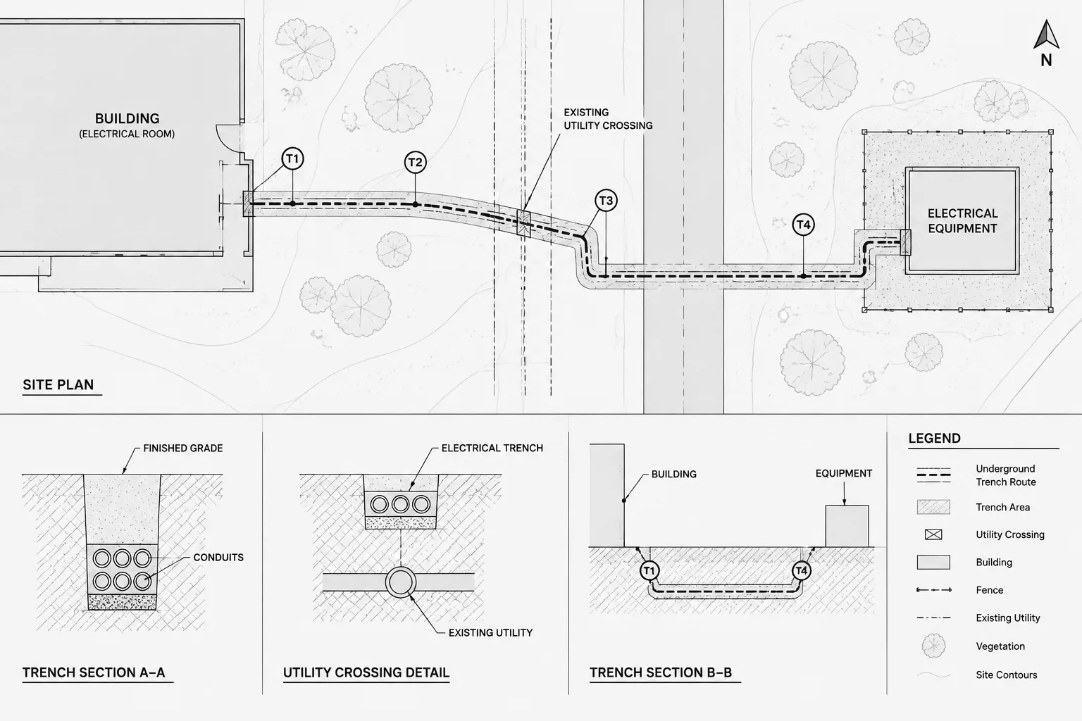
Electrical trench drawings in CAD connect underground routing with the broader electrical, civil, structural, and utility documentation. Their value depends on more than clean linework: plans, profiles, sections, callouts, and schedules must describe the same route without implying that uncertain information has been verified.
The following reference explains how to divide underground electrical information among drawing views, document utility crossings, manage route identifiers, and keep revisions coordinated. It is intended as a drafting and documentation guide; project requirements and approved design information remain the controlling sources.
Electrical trench drawings in CAD communicate more than the path of an underground raceway. A coordinated drawing may need to show route limits, changes in direction, building entry points, utility crossings, section references, equipment connections, and the relationship between plan and profile information.
The drafting challenge is deciding what belongs on the overall electrical site plan, what requires an enlarged plan, and what should be documented in a profile or typical section. A single heavy line with a conduit note may be adequate during an early study, but it rarely provides enough information for detailed coordination.
This guide focuses on organizing trench and crossing information in an electrical drawing set. Project dimensions, burial requirements, separation criteria, materials, and installation details must come from the project design and applicable requirements; they should not be inferred from generic CAD content.
Understand the Drawing Types
Underground electrical work is often represented through several related views. Each view answers a different documentation question.
| Drawing view | Primary purpose | Typical content |
|---|---|---|
| Overall site plan | Shows route context | Sources, destinations, major route segments, buildings, roads, property features, and key references |
| Enlarged trench plan | Shows local coordination | Bends, entries, structures, crossings, offsets, route tags, and nearby utilities |
| Profile | Shows vertical relationships | Ground or finished surface, route elevations, changes in depth, crossings, and structure connections |
| Cross section | Shows trench arrangement | Raceway grouping, envelope, cover reference, warning or protection elements, and adjacent features |
| Detail | Explains a specific condition | Building entry, transition, crossing treatment, termination, or connection to a structure |
Do not force all of this information into one plan. Separating route context from installation detail usually produces a more readable and maintainable set.
Build the Plan from Reliable Backgrounds
Begin with the current civil, architectural, landscape, and utility backgrounds. Attach them as external references where the project workflow permits, and confirm that every discipline uses the same coordinate system, base point, orientation, and drawing units.
The background should provide enough context to evaluate the electrical route without dominating the sheet. Retain relevant curbs, paving limits, walls, foundations, grading features, utility structures, and known services. Screen or hide unrelated objects that make the route difficult to read.
Avoid tracing background utilities unless the project requires controlled electrical copies. Duplicate geometry can become outdated when the originating discipline revises its model or drawing. When a utility must be represented directly in the electrical file, identify its source and update responsibility.

Draft the Trench as an Identifiable Route
A trench route should be more than an untagged polyline. Use a consistent graphical convention and divide the route into logical segments where conditions change. Segment breaks may occur at structures, bends, branch points, road crossings, building entries, or transitions between installation types.
Depending on the project, a route can be represented by a centerline, an outlined corridor, or a combination of both. A centerline is efficient for overall plans, while an outlined corridor may help with spatial coordination in congested areas. Do not imply an exact width with parallel lines unless that width is supported by design information.
Useful Route Annotations
- A unique trench, duct bank, or route identifier
- Source and destination references
- Raceway or cable schedule reference
- Section and detail callouts
- Continuation references at match lines
- Structure, pull point, or handhole identifiers
- Notes for transitions or special coordination conditions
Keep long technical descriptions out of crowded plan areas. Use tags that connect the route to schedules, notes, profiles, and details elsewhere in the set.
Document Utility Crossings Clearly
A crossing occurs where the electrical route passes above, below, or near another service or site feature. The plan establishes the horizontal location, but it may not prove whether the vertical arrangement is feasible. Important crossings should therefore receive a unique identifier and a corresponding profile, section, or coordination note.
Show the crossing marker at the actual intersection rather than placing it at a visually convenient but ambiguous location. Identify the other utility by type when that information is verified. If its position or elevation is based on incomplete background information, distinguish it from confirmed data through notation rather than presenting it as exact.
A practical crossing callout can reference:
- The electrical route segment
- The utility or physical feature being crossed
- A profile, section, or enlarged plan
- Known elevation information and its source
- An unresolved coordination item, if applicable
Avoid resolving uncertain crossings by moving CAD lines solely to make the plan look clear. Graphical separation is not the same as physical clearance. Where information is missing, flag the issue for coordination.
Use Profiles for Vertical Coordination
A profile converts a horizontal route into a longitudinal view. It is particularly useful where grading changes, existing utilities cross the route, or the trench connects to structures at controlled elevations.
Establish a route direction and keep it consistent between the plan and profile. Label the profile start and end so reviewers can understand its orientation without guessing. Reference recognizable route points such as bends, crossings, structures, and building lines.
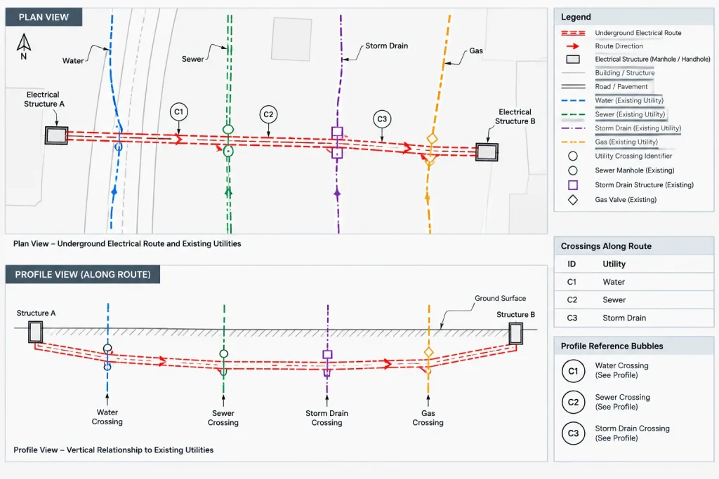
The profile may show existing or proposed surface information, the electrical route, utility crossings, and connection elevations. Clearly differentiate verified elevations from approximate or unavailable information. If horizontal and vertical presentation scales differ, state the applicable drawing scales in accordance with the project’s drafting practice and avoid measuring from a distorted view.
Create Sections that Match the Plan
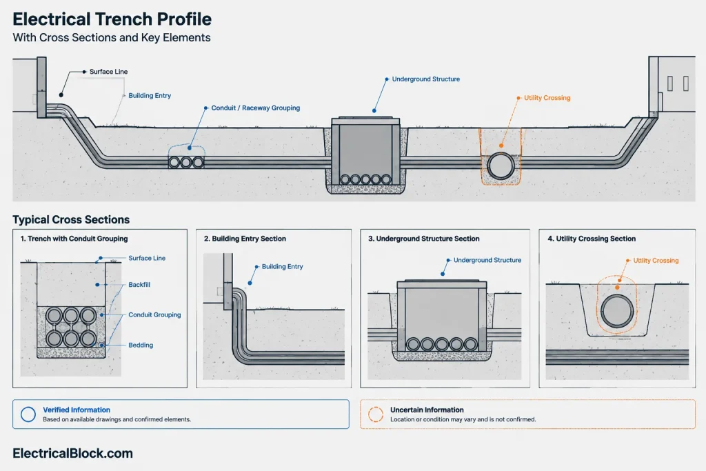
A trench section should explain the arrangement at a defined location. It should not be treated as a universal detail if the route contains several different conditions.
For example, a project may require separate sections for an open site area, a paved area, a utility crossing, and a building approach. Give each configuration a distinct section or type identifier and place matching references on the plan.
A coordinated section can identify:
- The trench or route type
- Raceway grouping and relative arrangement
- Concrete, fill, protection, or encasement where designed
- Surface condition
- Reference elevation or cover terminology
- Adjacent utilities or structural constraints
- Notes directing users to project specifications or schedules
Use dimensions only when they are supported by the project design. Generic block geometry should not become an accidental construction dimension.
Coordinate Entries, Structures, and Route Transitions
Trench documentation should terminate at recognizable connection points. At a building, coordinate the route with foundations, walls, structural openings, electrical room layouts, and equipment connection locations. At an underground structure, coordinate the plan symbol with the structure identifier, routing direction, and associated details.
Transitions deserve particular attention. A route may change from direct burial to a structured raceway grouping, turn upward at equipment, enter a pull structure, or divide toward multiple destinations. Mark the transition in plan and reference the detail or section that explains it.
When an exact entry point remains unresolved, do not draw a precise penetration that appears approved. Use a clearly labeled coordination zone or preliminary connection point until structural and equipment information is available.
Organize Layers for Review and Plotting
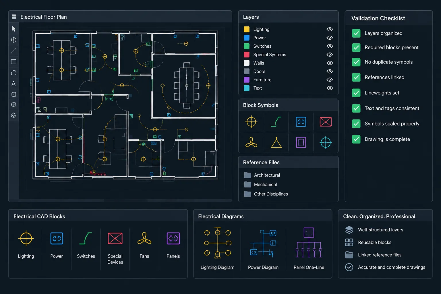
Separate trench information according to function rather than placing every object on one underground-electrical layer. A workable layer structure may distinguish routes, route outlines, structures, crossing markers, annotations, dimensions, profiles, and section graphics.
Existing, new, future, and demolition conditions should also remain graphically distinguishable. Layer names and line conventions should follow the project CAD standard, but their purpose should be obvious to anyone reviewing the file.
Use layer states or controlled view configurations to create different outputs from the coordinated model. An overall routing sheet may suppress minor crossing text, while an enlarged coordination sheet can display utility references and detailed callouts.
Connect the Drawings to Schedules and Diagrams
The trench route is only one part of the electrical documentation. Its identifiers should agree with raceway schedules, cable schedules, equipment plans, site one-lines, riser diagrams, and structure details where those documents are included.
Check that the source and destination shown on the plan match the associated schedule entries. If a route branches, verify that the diagram and plan describe the same topology. If a structure is renamed, update every plan, profile, detail, and schedule reference rather than correcting only the visible sheet.
Review the Drawing as a Coordinated System
Before issue, review the underground route in context rather than checking individual sheets in isolation.
- Confirm that route identifiers are unique and consistent.
- Trace every route from source to destination.
- Verify that section and detail references point to existing views.
- Check crossings against the latest available utility backgrounds.
- Compare plan turns and branches with profiles and diagrams.
- Identify unresolved elevations or locations as coordination items.
- Check that text, markers, and crossing symbols remain readable at plotted scale.
- Remove obsolete alternatives and abandoned route graphics.
- Confirm that externally referenced backgrounds are current.
- Review building entries and structure connections with the relevant disciplines.
Well-organized electrical trench drawings make uncertainty visible instead of concealing it. By separating overall routing, vertical coordination, crossing conditions, and construction sections into related views, the CAD set becomes easier to review and revise. The result is not merely a cleaner site plan, but a connected documentation system that helps project teams understand where the route goes, what it crosses, and where additional verification is required.
A Practical Reading Sequence for Trench Drawing Sets
A reviewer should be able to begin with the overall site plan, locate a route identifier, follow that route to an enlarged area, and then find the applicable profile, section, detail, and schedule entry. This reading sequence is a useful test of whether the drawing set functions as a connected system rather than a collection of isolated views.
Route identifiers provide the main link between drawings. Crossing markers identify locations that need focused coordination, while section and detail references explain local arrangements. Profiles add the vertical information that a plan cannot communicate clearly. When these references agree, users can move through the set without relying on assumptions.
Separate Designed Conditions from Background Information
Underground drawings often combine electrical design content with information received from surveys, record drawings, utility files, and other disciplines. These sources may have different levels of reliability. Use graphical conventions and notes that distinguish controlled design geometry from reference information, approximate locations, and unresolved coordination items.
This distinction is especially important at utility crossings and building entries. A precise-looking CAD intersection can appear authoritative even when the underlying utility position is uncertain. The drawing should communicate the status of the information instead of allowing linework precision to imply field accuracy.
Manage Revisions Across Every Related View
A route change can affect more than the site plan. Moving a segment may alter crossing locations, profile references, structure connections, section types, schedule entries, and diagram topology. Revision review should therefore follow the route through every related document.
- Check whether crossing markers still align with the revised route.
- Confirm that profile direction and route references remain correct.
- Review affected section and detail callouts.
- Update source and destination references where routing changes alter connections.
- Remove superseded geometry and annotations from working and plotted views.
- Record unresolved conditions as coordination items rather than concealing them graphically.
This route-based review method helps prevent a common documentation problem: a revised plan paired with an outdated profile, schedule, or detail.
Frequently Asked Questions
What is the difference between a trench plan and a trench profile?
A trench plan shows the route in horizontal context, including destinations, bends, structures, crossings, and nearby site features. A profile shows the route longitudinally so that surface conditions, elevation changes, utility crossings, and structure connections can be coordinated vertically.
When should a utility crossing receive a separate detail or section?
A separate view is useful when the plan alone cannot communicate the physical relationship, when vertical information affects coordination, or when the crossing has a condition that differs from the typical route. The need should be based on project information rather than assumed from generic CAD geometry.
Should an electrical drafter copy utility lines into the electrical file?
Keeping the originating discipline’s background as a controlled reference generally reduces duplicate geometry. If utility objects must be copied into the electrical file, the drawing workflow should identify their source, status, and update responsibility.
How should uncertain utility information appear in CAD?
Use the project’s approved notation to distinguish approximate, unverified, or incomplete information from confirmed geometry. Add a coordination note or status indicator where needed, and avoid drawing an exact-looking relationship that has not been established.
Why are route identifiers important?
Route identifiers connect plan segments with profiles, sections, details, schedules, diagrams, and continuation references. Consistent identifiers also make it easier to trace revisions and confirm that source and destination information agrees throughout the drawing set.
Can one typical section represent an entire trench route?
Only when the documented condition truly remains applicable. Routes that pass through different surface conditions, crossings, approaches, or transitions may require distinct section references so the drawings do not imply a universal arrangement.










Leave a Reply
You must be logged in to post a comment.