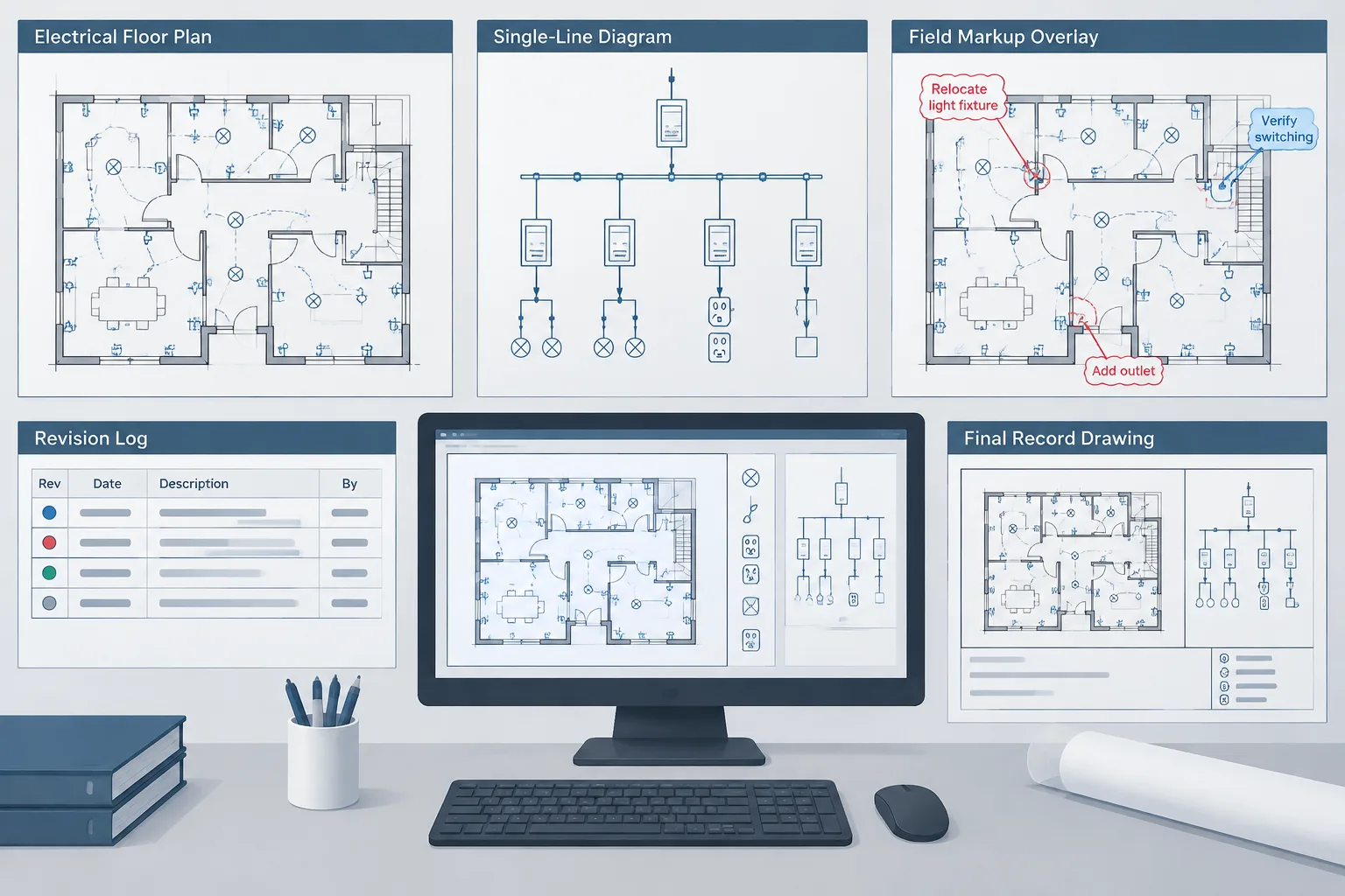
Electrical record drawings in CAD should show more than a cleaned-up version of the latest plan. They should communicate which project records informed the edits, how related drawing references were coordinated, and where the available information remains limited.
This guide focuses on the documentation workflow behind that result. It is intended for CAD drafters, designers, reviewers, and closeout teams converting field markups into a controlled final set without treating unverified information as confirmed field conditions.
Electrical record drawings document the installation information available at project closeout. Producing them involves more than removing revision clouds and changing a title block status. A drafter must interpret field markups, reconcile conflicting information, update related views, and preserve a clear trail showing where each change originated.
The quality of the final set depends heavily on the quality of the source information. CAD files can accurately represent submitted markups, but they cannot confirm concealed routing, equipment characteristics, or field conditions that were never recorded. A disciplined workflow should therefore distinguish documented changes from assumptions and unresolved questions.
Record Drawings, As-Built Markups, and Design Drawings
These terms are sometimes used interchangeably, but they can describe different project documents. Naming conventions should follow the project requirements and the responsible professional’s direction.
| Document | Typical purpose | Important limitation |
|---|---|---|
| Design drawing | Communicates the intended electrical work before or during construction. | It does not automatically represent final field conditions. |
| Field markup | Records reported deviations, clarifications, and installation changes on a working drawing. | Its accuracy depends on who created it, when it was created, and what was observable. |
| Record drawing | Incorporates accepted project information into a coordinated final drawing set. | It represents the records provided for drafting, not an independent survey unless specifically verified that way. |
The final title and status should not imply a level of verification that the project team did not perform. If the CAD team is transcribing contractor markups, the documentation process should preserve that distinction rather than silently presenting every edit as independently confirmed.
Build a Controlled Markup Intake Process
Record-drawing problems often begin before editing starts. Markups may arrive as scanned prints, photographs, PDF comments, sketches, meeting notes, revised shop drawings, or separate CAD files. If these sources are not logged, it becomes difficult to determine whether an edit was overlooked, superseded, or duplicated.

Create an intake register that identifies each source by a unique reference. Useful fields include:
- Source title or file name
- Date received
- Originator or responsible party
- Affected sheet, area, system, or equipment
- Review status
- Superseded-source reference
- Open question or clarification status
- Date incorporated into CAD
Preserve the original source files in a read-only folder or controlled document system. Work from copies when highlighting or adding review comments. This prevents the evidence behind a CAD change from being overwritten.
Review Markups Before Editing CAD
A preliminary review helps identify incomplete instructions and coordination impacts. For example, a markup moving a panel on a floor plan may also affect the equipment schedule, feeder representation, single-line diagram, room elevation, and sheet references. Updating only the visible plan symbol would leave the record set internally inconsistent.
Classify each markup
Sorting edits by type makes the work easier to assign and check. Practical categories include:
- Location change: A device, outlet, panel, junction box, disconnect, or other item has moved.
- Identity change: A tag, equipment name, circuit reference, or drawing label has changed.
- Routing change: A reported raceway, cable tray, underground route, or feeder path differs from the design drawing.
- Quantity change: Devices or equipment were added, removed, or consolidated.
- Connection change: The documented source, destination, circuit, feeder, or control relationship has changed.
- Documentation correction: A note, callout, detail reference, or schedule entry needs revision without representing a field change.
Separate clear edits from questions
Do not resolve unclear markups by guessing. A line drawn near several raceways, an equipment tag with illegible characters, or a note without a destination reference should be entered into a clarification log. The CAD model should not become the place where uncertainty disappears without review.
Use a Working Copy with Visible Change Control
Begin from the correct issued CAD baseline and confirm that all referenced backgrounds, fonts, plot resources, and support files are available. Save a controlled working copy rather than editing the last issued set directly.
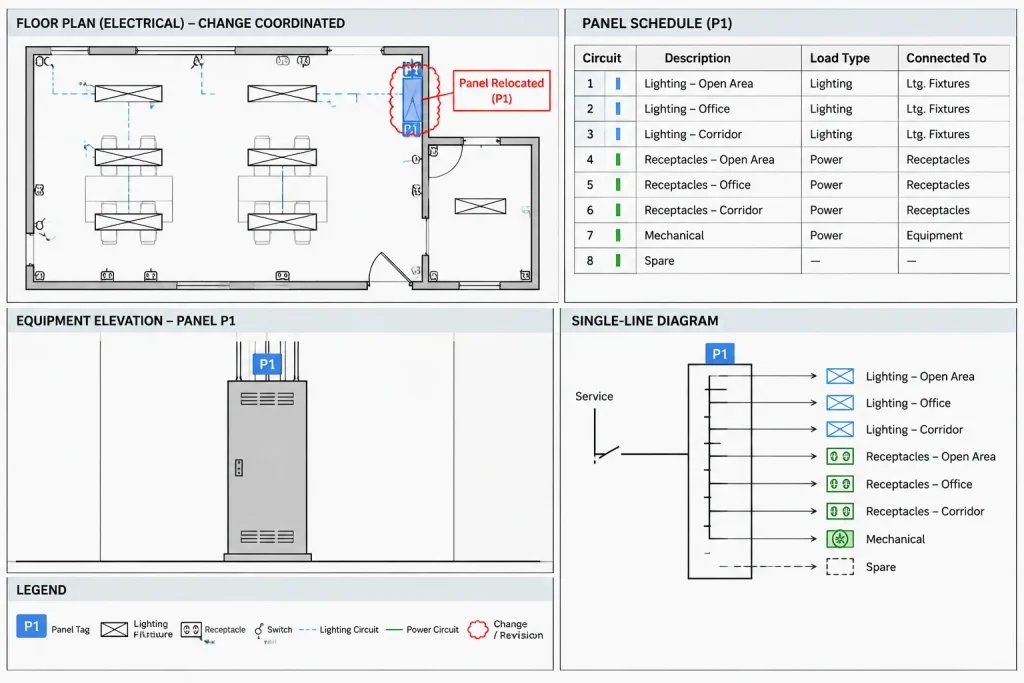
During production, make changes visually traceable. The exact method can vary by office, but it may use temporary revision layers, color overrides, review clouds, status attributes, or separate check plots. Temporary graphics should clearly distinguish pending work from permanent record content.
Maintain existing project conventions for layers, blocks, annotation, and sheet organization. Record drawings should not become an unplanned CAD standards conversion unless that work is separately authorized. Replacing every legacy symbol or renaming all layers can introduce unrelated changes and make comparison with previous issues more difficult.
Coordinate Every Change Across the Drawing Set
An electrical item may appear in multiple representations. A panel can be shown as a plan symbol, an elevation outline, a single-line node, and a schedule heading. A luminaire can appear on a reflected ceiling plan, in a fixture schedule, and in a control diagram. Record-drawing edits should follow these relationships.
| If this changes | Also review |
|---|---|
| Equipment location or tag | Schedules, one-lines, elevations, details, feeder references, and room names |
| Circuit assignment | Panel schedules, circuit annotations, home runs, load summaries, and related control references |
| Feeder source or destination | Single-line diagrams, risers, feeder schedules, equipment tags, and continuation references |
| Device quantity or type | Plan symbols, legends, schedules, notes, and associated circuiting |
| Raceway or cable route | Plans, sections, details, pull points, penetrations, and route tags |
| Room name or number | Device location descriptions, schedules, keynotes, and cross-referenced sheets |
A useful review technique is to search the drawing set for the affected tag before and after editing. Block attributes, schedule text, diagram labels, and note references may contain the same identifier in different formats. Search results should still be checked visually because exploded text, external references, and graphical schedules may not behave like database records.
Document Uncertainty Without Inventing Detail
Not every field condition can be reconstructed from closeout information. Concealed raceways may have unknown intermediate routing. A markup may confirm that equipment moved without documenting the exact path of its feeder. In such cases, avoid drawing a precise route merely to make the plan look complete.

Use project-approved notation to identify information that is approximate, diagrammatic, based on provided records, or not verified. Notes should be specific enough to explain the limitation without turning the sheet into a narrative report. Keep unresolved technical decisions with the responsible reviewer rather than encoding assumptions into blocks or linework.
Check CAD Quality and Drawing Meaning Separately
A clean file is not necessarily an accurate record drawing. Quality control should include both CAD integrity and electrical-document coordination.
CAD checks
- Confirm external references resolve correctly and use the intended backgrounds.
- Remove temporary clouds, highlights, and review layers only after approval.
- Check block attributes, text placement, leaders, and annotation visibility.
- Review layer states and viewport visibility on every affected sheet.
- Plot the complete sheet set using the intended publishing workflow.
- Check that no unrelated geometry changed during editing.
Documentation checks
- Compare each accepted source markup with the updated output.
- Confirm that tags and names match between plans, schedules, and diagrams.
- Review continuation symbols and cross-references in both directions.
- Check that removed equipment is not still listed elsewhere.
- Verify that added items are represented wherever the drawing set requires them.
- Confirm that legends still match the symbols actually used.
Close Out the Record Set
Before publishing, reconcile the markup register. Every source item should have a disposition such as incorporated, superseded, not applicable, rejected by the responsible reviewer, or awaiting clarification. An unchecked markup should not disappear simply because drafting is complete.
Archive the final CAD files, published sheets, source markups, clarification log, and issue information together. Keep file naming and issue dates consistent across the package. If editable files are delivered, include the support files required to reproduce the drawings according to the agreed handoff requirements.
The central principle is traceability: a reviewer should be able to connect a final CAD change to its source and identify any limitation attached to it. That discipline produces electrical record drawings that are not only visually clean, but also more reliable for future maintenance, renovation planning, and drawing coordination.
Create a Change-Level Provenance Trail
A source register identifies the documents received, but a change-level record connects those documents to specific CAD edits. This added layer of provenance is especially useful when a markup affects several sheets or when different sources address the same equipment.
For each accepted change, the project team can record:
- Source reference: The markup, comment, sketch, or reviewer direction supporting the edit.
- Affected content: The sheets, views, schedules, diagrams, blocks, or annotations reviewed.
- Drafting disposition: Whether the information was incorporated, superseded, rejected, or held for clarification.
- Verification basis: Whether the change came from provided records, an authorized review decision, or another documented project source.
- Known limitation: Any routing, location, identity, or relationship that remains approximate or unconfirmed.
This record does not need to appear on the published sheets. It can remain in the project documentation system, provided it stays associated with the final CAD package and can be retrieved during later review.
Control Cleanup Changes as Carefully as Field Changes
Closeout editing often reveals misaligned text, inconsistent blocks, obsolete notes, or other drafting defects. Correcting them may improve readability, but undocumented cleanup can also obscure the difference between a field-driven revision and an editorial adjustment.
Compare the final output against the issued baseline as well as the accepted markups. If an unrelated correction is necessary, identify it separately in the review record. This helps prevent harmless-looking cleanup from changing circuit references, equipment identities, diagram relationships, or the apparent scope of installed work.
Prepare the Set for Future Interpretation
A future user may not have access to the people who prepared the closeout package. The drawings should therefore make their documentation basis understandable without overstating certainty. Consistent status language, retained source records, coordinated identifiers, and explicit limitations allow later maintenance or renovation teams to judge what the drawings do and do not establish.
The most useful final package is not necessarily the one with the most detail. It is the one in which every included detail has a supportable origin and unresolved information remains visible to the appropriate reviewer.
Frequently Asked Questions
Are record drawings the same as field-verified as-built drawings?
Not necessarily. A record set may be based on contractor markups, review comments, approved revisions, and other closeout records. Its title and notes should reflect the actual basis of preparation rather than imply an independent field survey that did not occur.
What should a drafter do when field markups conflict?
Keep both sources in the intake record, identify the conflict, and request direction from the responsible reviewer. Do not select the more convenient interpretation simply because it produces cleaner CAD linework.
Should existing CAD standards be rebuilt during record-drawing production?
Only when that work is specifically authorized. Broad layer, block, or annotation conversions can create changes unrelated to the field records and make comparison with earlier issues more difficult.
How can reviewers find missed coordination changes?
Search for the affected equipment tag, circuit reference, room identifier, or route label throughout the set, then inspect the results visually. Plans, schedules, diagrams, details, and external references may represent the same item differently.
What belongs in the closeout archive?
Retain the final CAD package, published drawing set, source markups, clarification records, change dispositions, and the support files required by the agreed handoff process. The archive should preserve the connection between the final edits and their documented sources.
How should unknown concealed routing be shown?
Use the project-approved method for identifying approximate, diagrammatic, or unverified information. Avoid adding a precise path when the available records establish only the endpoints or a general routing condition.












Leave a Reply
You must be logged in to post a comment.