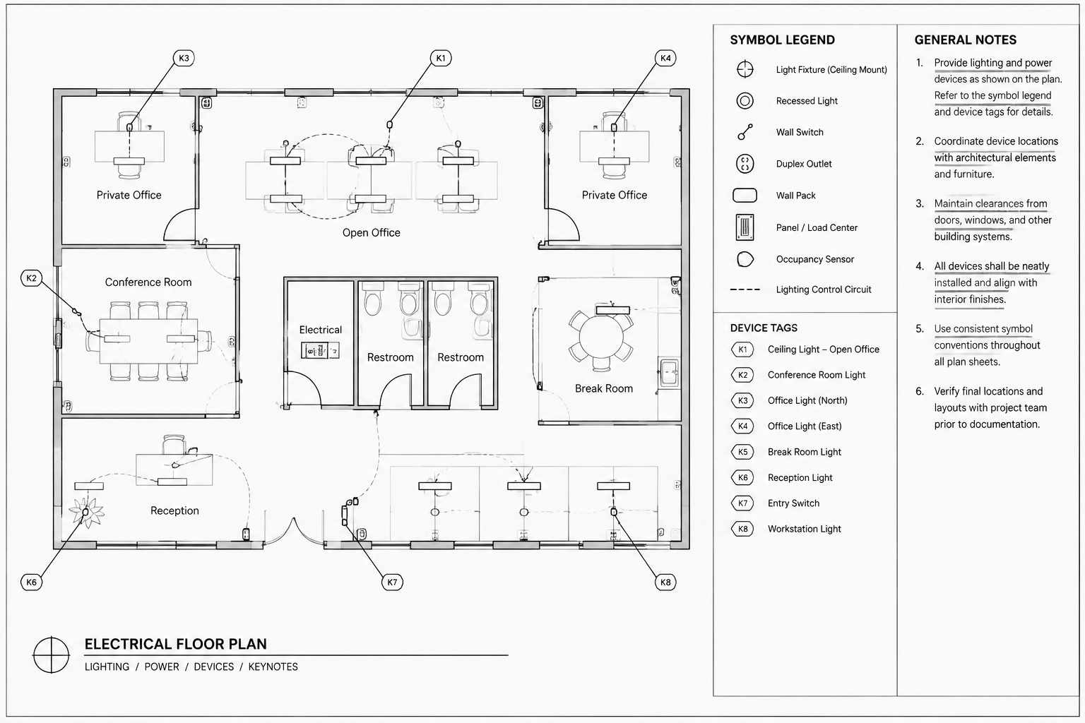
Electrical plan keynotes, general notes, symbol tags, and legends may look similar on a finished sheet, but they serve different documentation purposes. Choosing the correct annotation type helps readers connect plan graphics with schedules, diagrams, details, and project requirements without searching through unrelated text.
This guide explains how to organize those annotation types within an electrical CAD workflow, maintain clear references, and review the resulting sheets for consistency. The emphasis is on drawing communication and coordination; project-specific requirements should always be confirmed against the current design documents and drafting procedures.
Electrical drawings communicate through more than lines and symbols. Notes, tags, legends, and references explain what the graphics mean, identify where requirements apply, and connect plan views to schedules or details. When these elements are poorly organized, a technically correct plan can still be difficult to interpret.
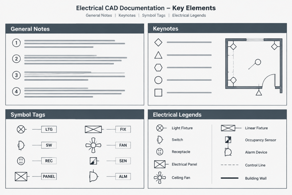
A reliable CAD workflow gives each type of annotation a specific job. General notes should establish broad drawing conventions, electrical plan keynotes should address selected conditions, symbol tags should identify devices or equipment, and legends should define the graphic language used in the set. Keeping those functions separate makes drawings easier to review, revise, and coordinate.
The Four Main Annotation Types
The terms used by different firms may vary, but most electrical plan annotation can be organized into four functional groups.
| Annotation type | Primary purpose | Typical location |
|---|---|---|
| General note | States information that applies broadly to a drawing, discipline, or set | Notes column, cover sheet, or discipline information sheet |
| Keynote | Connects a short plan marker to a condition-specific instruction | Marker in the plan with a corresponding list near the view |
| Symbol tag | Identifies a device, fixture type, equipment item, circuit, or scheduled object | Beside the associated symbol or object |
| Legend entry | Defines the meaning of a graphic symbol, line type, abbreviation, or notation | Legend sheet or drawing-specific legend |
One annotation should not be forced to perform all four roles. For example, a receptacle type tag can identify a scheduled type, but it should not also carry a long installation instruction. A keynote can describe a special condition, but it should not replace a symbol definition that readers need throughout the project.
What Belongs in Electrical General Notes?
General notes are best for instructions and drawing conventions that apply repeatedly. They can explain the intended relationship between electrical plans and other disciplines, identify how concealed routing is represented, or state that the drawing must be read with associated schedules and diagrams.
A useful general note is broad enough to apply in multiple locations but specific enough to guide interpretation. Avoid using general notes as a storage area for unrelated requirements. Long lists containing design assumptions, coordination reminders, product descriptions, and isolated field conditions become difficult to review.
Good candidates for general notes
- Drawing-wide graphic conventions not already defined in the legend
- General coordination requirements involving architectural, mechanical, plumbing, structural, or technology drawings
- Explanations of whether routing shown is diagrammatic or intended to represent a coordinated path
- Instructions to coordinate equipment connections with approved equipment information
- General relationships among plans, schedules, single-line diagrams, risers, and details
Do not repeat the same general note on every plan unless the project documentation method requires it. Repetition creates another revision risk: one copy may be updated while another remains unchanged.
When to Use Electrical Plan Keynotes
Keynotes are effective when a condition needs a specific instruction but the full text would clutter the plan. A keynote marker is placed near the relevant object or area, and its identifier points to a note in a nearby list.
Use a keynote when the instruction applies to a limited location, a defined group of objects, or an unusual coordination condition. Examples include identifying an existing device to remain, directing the reader to a related detail, describing a special connection shown only in one room, or clarifying the extent of work at a plan boundary.
A keynote should answer an obvious question raised by the plan. It should not merely restate what the symbol already shows. If the drawing contains a luminaire symbol with a clear type tag, a keynote saying that the object is a luminaire adds little value. A note describing a special mounting or coordination condition may be useful, provided that information has been verified for the project.
Sheet keynotes versus master keynotes
Sheet keynotes list only the notes used on a particular sheet or view. This keeps the list relevant and helps readers find the referenced text quickly. Master keynote systems use identifiers from a larger controlled note library. They can improve consistency, but unused notes should not appear as if they apply to the current drawing.
Whichever method is selected, identifiers should remain stable during routine editing. Renumbering every note after deleting one can create unnecessary redline work and may break references in review comments. A controlled gap in a sequence is often less confusing than changing multiple established markers, subject to the project team’s documentation rules.
How Symbol Tags Differ from Keynotes
A symbol tag identifies an object; a keynote explains a condition. The distinction is simple but important.
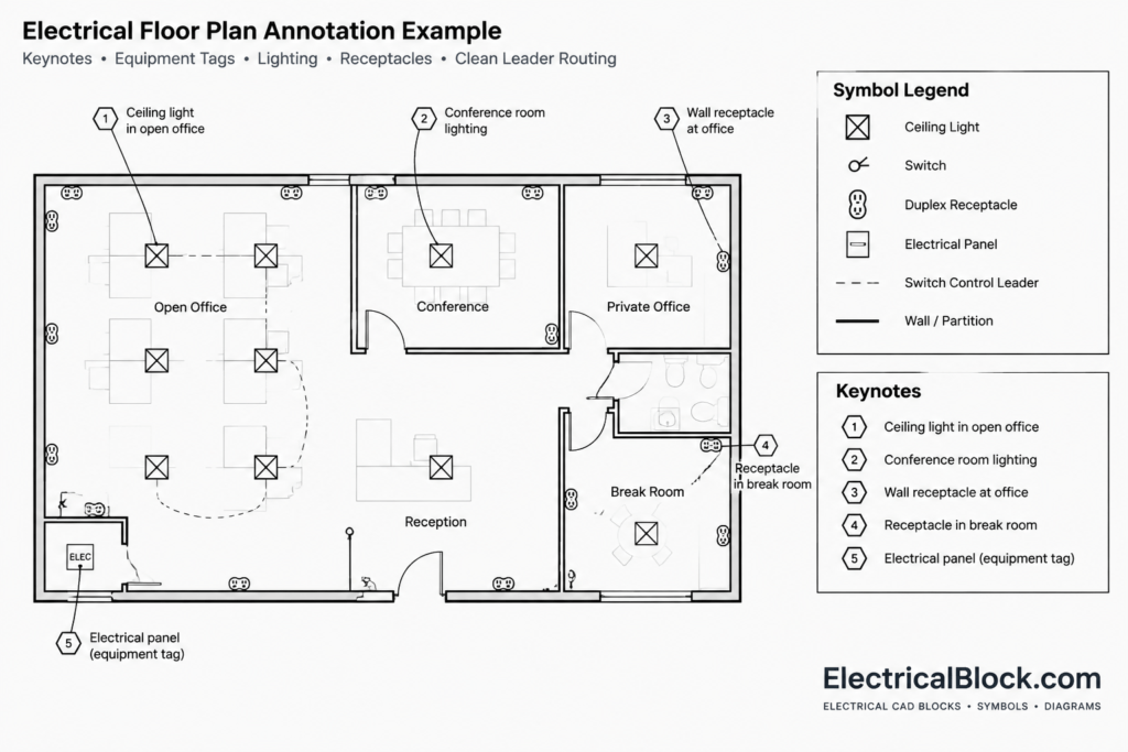
On a lighting plan, a tag may associate a luminaire symbol with a fixture schedule. On a power plan, a tag may identify equipment or a connection point. Panel and circuit annotations may connect a device to distribution information. These tags should follow a consistent structure so that readers can distinguish a type designation from a circuit reference, equipment identifier, or keynote marker.
Visual differentiation can come from the marker shape, text style, prefix, suffix, or placement convention. Do not rely only on color because printed sets, exports, and scanned markups may be monochrome. The distinction should remain readable in the intended plotted output.
Building a Useful Electrical Legend
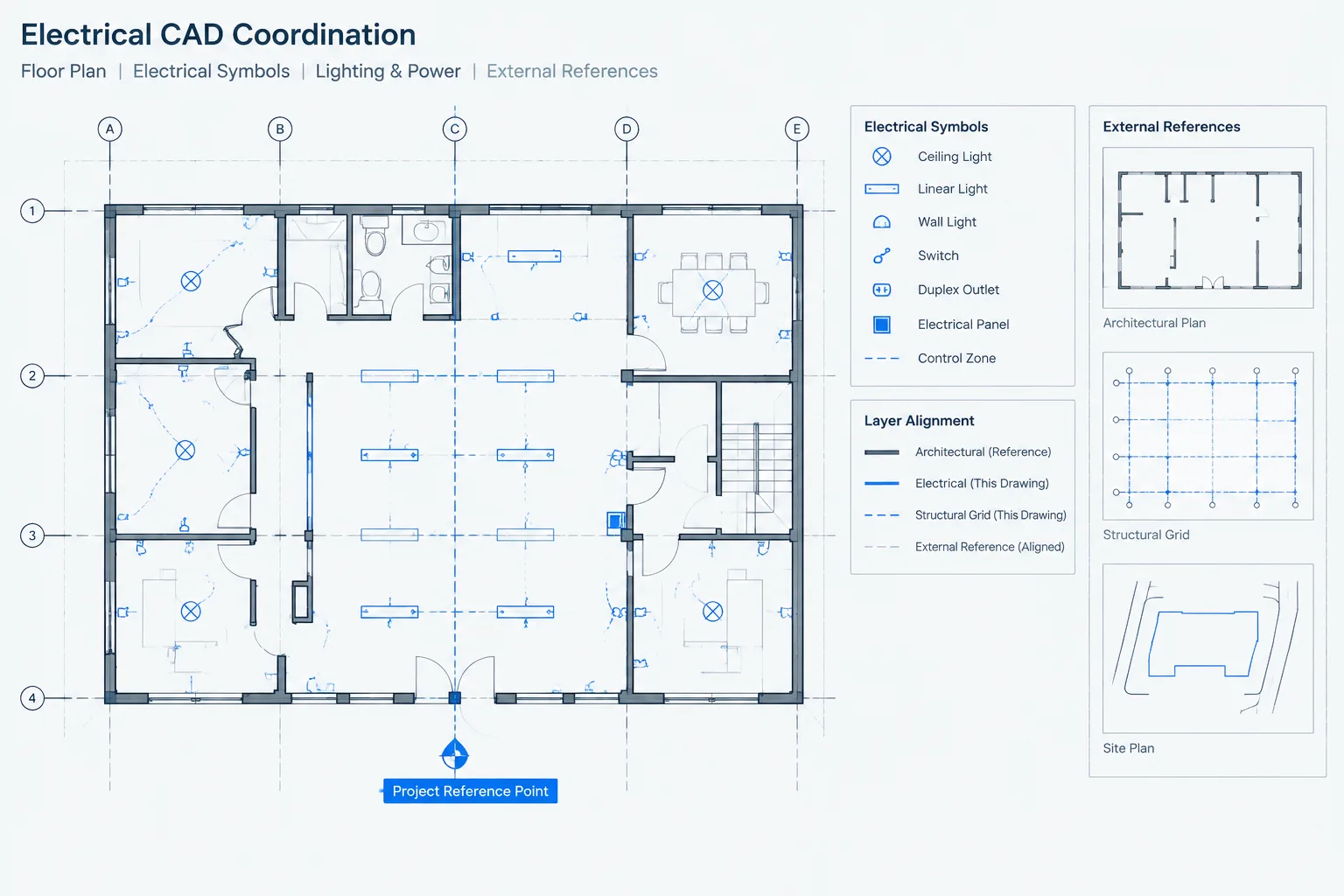
A legend is a decoding tool, not a catalog of every symbol available in the CAD library. Include symbols and abbreviations that are relevant to the issued drawing set. A huge legend containing unused blocks can make it difficult to determine which devices are actually part of the project.
Each legend entry should show the plotted symbol and a clear description. If symbols look different at separate scales or in different view types, confirm that the legend representation still matches the plan. Where similar symbols represent different device types, the differentiating feature must survive plotting and PDF export.
Legend quality checks
- Confirm that every plan symbol has a corresponding definition or an unambiguous schedule reference.
- Remove obsolete entries after verifying they are not used elsewhere in the set.
- Check that symbol names match schedule terminology.
- Verify that line types remain distinguishable at the issue scale.
- Review abbreviations for duplicate meanings.
- Make sure existing, new, relocated, and removed work are differentiated consistently where those categories are used.
A Practical CAD Annotation Workflow
1. Establish the annotation hierarchy
Before drafting notes, decide which information belongs in general notes, keynotes, tags, legends, schedules, and details. This prevents the same instruction from appearing in several places.
2. Use controlled text styles and layers
Assign annotation to clearly defined CAD layers according to the project standard. Keynote markers, note text, equipment tags, circuit text, and legend graphics may need separate visibility or plotting behavior. Use approved text styles rather than manually formatting individual notes.
3. Keep markers close to their targets
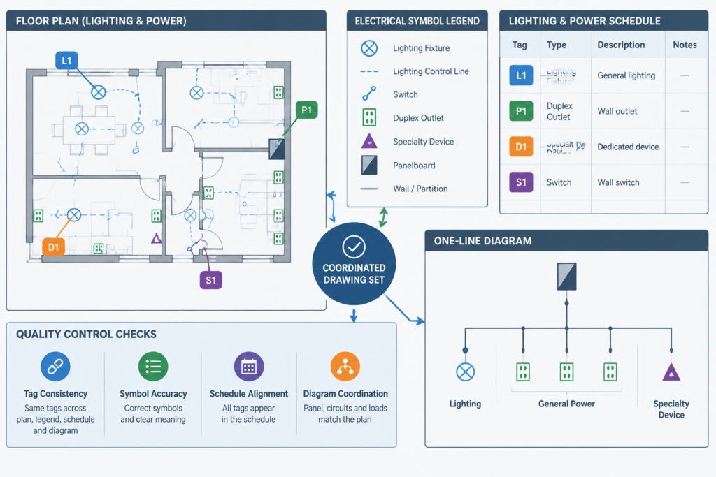
Place tags and keynote markers where their association is clear without covering architecture, device symbols, or circuiting. Use leaders when proximity alone could be ambiguous. Avoid crossing leaders where possible, and do not let a leader terminate between two potential targets.
4. Coordinate terminology
Compare annotation against equipment schedules, panel schedules, lighting schedules, single-line diagrams, risers, details, and specifications. The same item should not have conflicting names or identifiers across the drawing set.
5. Review at plotted scale
Annotations that appear clear while zoomed in may overlap or disappear when plotted. Review representative sheets as PDFs or prints using the intended output settings. Check text hierarchy, leader spacing, lineweights, screening, and marker recognition.
6. Validate references before issue
Search the drawing set for deleted identifiers, duplicate tags, empty keynote markers, and references to renamed details or sheets. Automated search tools can help, but a visual review is still necessary because some annotations may be embedded in blocks or represented as ordinary text.
Common Documentation Problems
- Orphaned keynotes: A marker remains on the plan after its note is removed, or a listed note has no marker.
- Ambiguous leaders: The leader points toward a group of devices without clearly identifying the intended object.
- Conflicting terminology: A plan tag, schedule row, and diagram label use different names for the same equipment.
- Notes used as design substitutes: A broad instruction attempts to cover information that should be drawn, scheduled, or coordinated.
- Unreadable annotation density: Too many notes and leaders collect in one area, obscuring the electrical and architectural graphics.
- Library-driven legends: The legend reflects available CAD blocks rather than symbols actually used in the project.
Final Review Principle
Every annotation should help the reader answer one of three questions: What is this object? What does this graphic mean? What special instruction applies here? Tags identify objects, legends define the visual language, and notes explain requirements or conditions. Maintaining that separation produces electrical CAD drawings that are easier to navigate and less vulnerable to coordination errors.
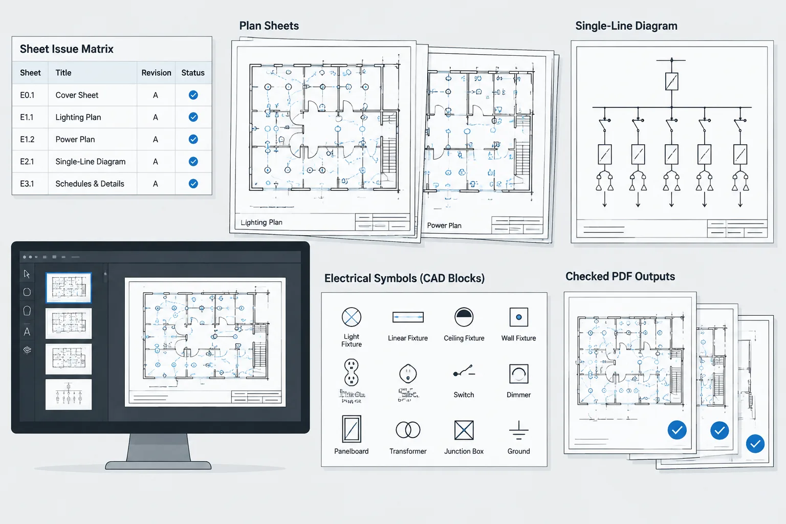
CAD blocks provide the graphic vocabulary, but disciplined annotation gives that vocabulary project-specific meaning. Before issuing a drawing, verify all notes, symbols, tags, and references against the current design documents and the project team’s drafting requirements.
Annotation Ownership and Revision Control
Clear annotation also depends on assigning each piece of information an authoritative location. If an equipment identifier originates in a schedule, the plan tag should match that schedule rather than become a separate source of naming information. If a condition is explained by a detail, the plan annotation should direct the reader to the detail without creating a conflicting summary.
Control editable annotation data
Tags generated from block attributes, object data, or linked fields should be checked for manual overrides. An override may make one view appear correct while leaving the underlying object or schedule unchanged. Where annotations are entered as ordinary text, include them in the same reconciliation process used for schedules and diagram labels.
Define drawing-space responsibility
Decide whether sheet-specific notes belong with the plan geometry, within an annotation view, or on the plotted sheet. Avoid placing local keynotes in a shared background or external reference unless they are intended to appear wherever that reference is used. Predictable ownership reduces accidental duplication and unwanted visibility.
Review relationships, not only wording
A spelling check cannot confirm that a marker points to the correct object or that a tag agrees with its schedule. Annotation review should follow each reference from its plan location to its destination and back again. This relationship-based check is especially useful after equipment changes, view rearrangement, schedule updates, or the removal of drawing details.
Use a focused handoff check
- Confirm that each annotation has one clear purpose and one identifiable target.
- Compare object tags with the current schedules and diagrams.
- Check that shared references do not contain unintended sheet-specific notes.
- Look for manually overridden attributes or fields.
- Verify that revised note text still matches every marker using it.
- Inspect the plotted output rather than relying only on the CAD editing view.
Frequently Asked Questions
Can the same instruction appear as both a general note and a keynote?
Duplication is usually best avoided. If the instruction applies broadly, it generally belongs in the general notes. If it applies only to a selected condition, a keynote provides a clearer connection. Repeating the text creates multiple locations that must remain synchronized.
Should electrical keynotes be stored in model space or paper space?
The appropriate location depends on the project CAD standard and sheet workflow. The important requirement is consistent ownership, visibility, scaling, and plotting behavior. Sheet-specific annotation should not be placed where it can unintentionally appear in unrelated views.
Should keynote text be embedded inside an electrical CAD block?
Embedding a long instruction in a reusable block can make revision control difficult. A block may contain a controlled tag or attribute, while the explanatory text is managed through the project’s keynote system. Any automated relationship should be tested after copying, renaming, or updating the block.
How can stale symbol tags be found?
Compare plan tags with the current schedules, diagrams, and equipment identifiers. Search tools and data extraction can help locate duplicates or unexpected values, but visual review is still needed to confirm that each tag is associated with the intended object.
Can color alone distinguish keynotes from equipment tags?
No. Color may support the hierarchy, but marker shape, text treatment, placement, or another visible convention should preserve the distinction in monochrome prints, PDF exports, and scanned markups.








Leave a Reply
You must be logged in to post a comment.