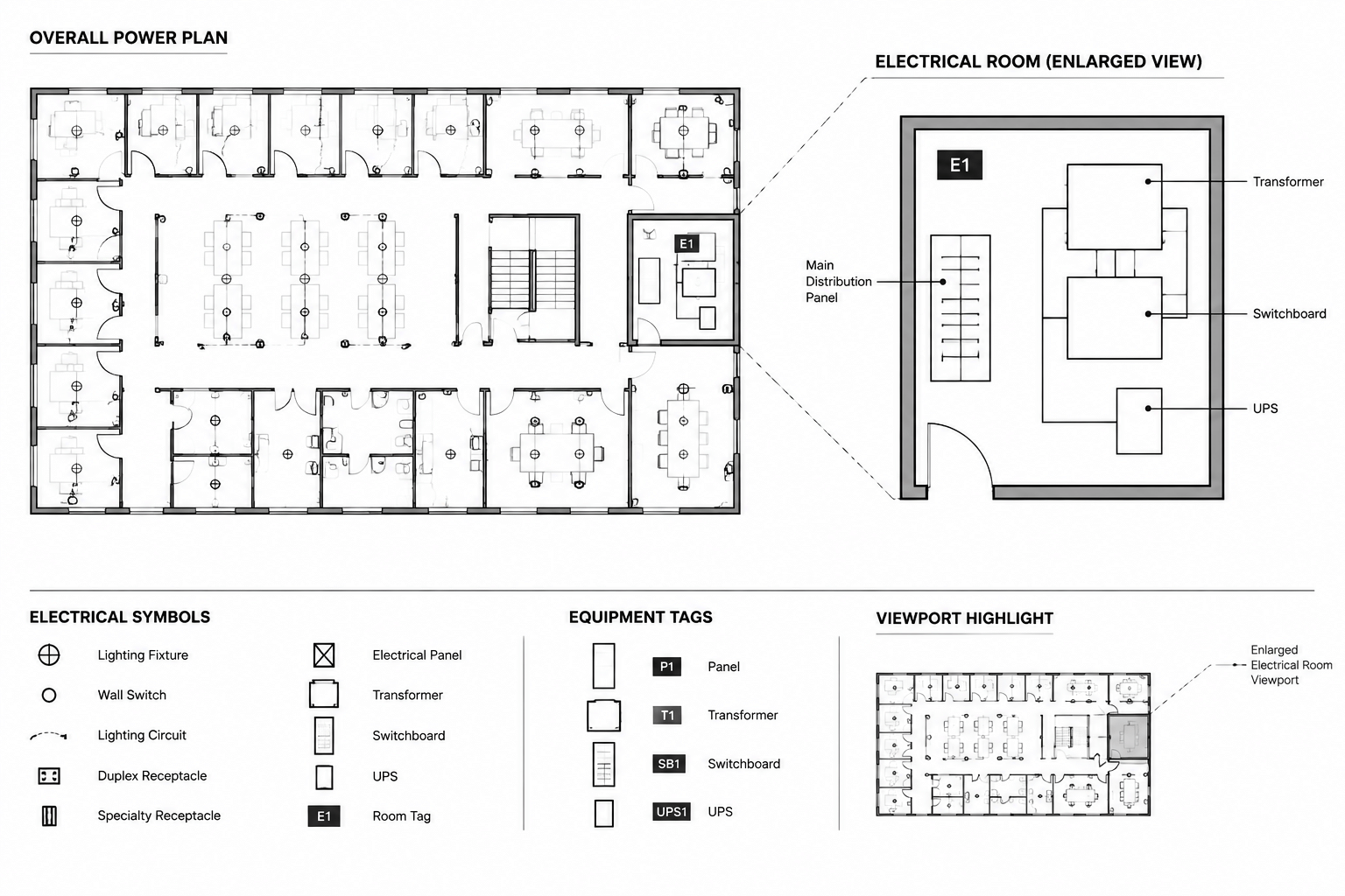
Readable electrical drawings depend on more than accurate geometry. Symbols, equipment tags, circuit notes, leaders, and references must retain a clear visual hierarchy when model information is presented through different sheet views.
This guide explains how to coordinate electrical CAD annotation scales without confusing diagrammatic graphics with physical equipment footprints. It also provides a practical framework for selecting an annotation method, managing enlarged views, and reviewing the plotted result.
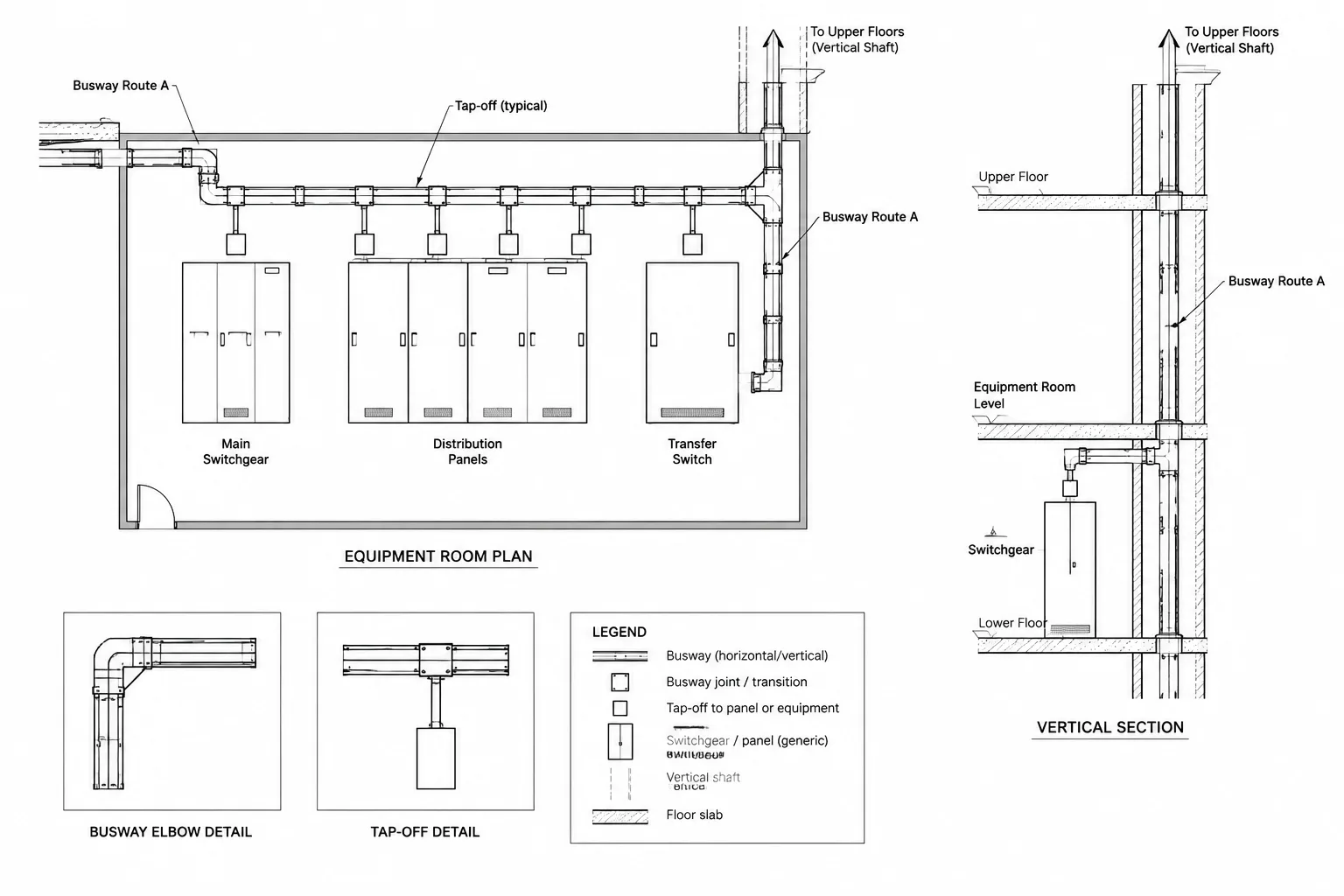
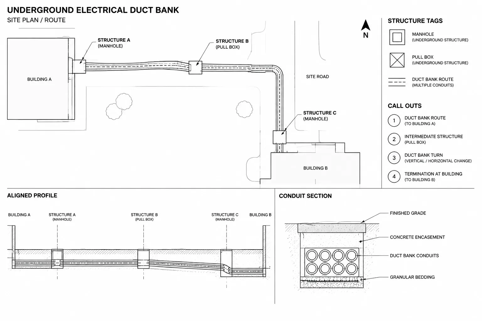
Electrical drawings often present the same design at several scales. A floor plan may show overall distribution, an enlarged electrical room may clarify equipment relationships, and a detail may explain a specific mounting or connection condition. The geometry can be accurate in every view while the finished sheets remain difficult to read if symbols, text, tags, and callouts are not managed consistently.
A reliable electrical CAD annotation scale workflow separates real-world geometry from sheet-readable graphics. It also distinguishes physical objects, such as equipment footprints, from diagrammatic symbols that communicate function rather than actual size. This distinction helps a drawing set remain legible without misrepresenting design intent.
What annotation scale controls
Annotation scale is the relationship between information drawn in the CAD model and its intended appearance on a plotted or exported sheet. It commonly affects:
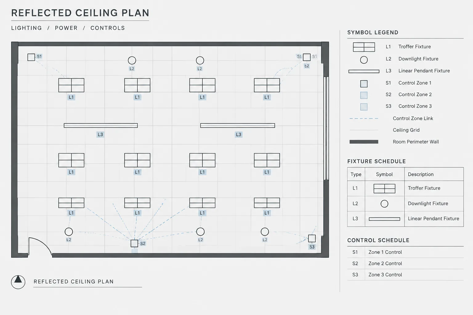
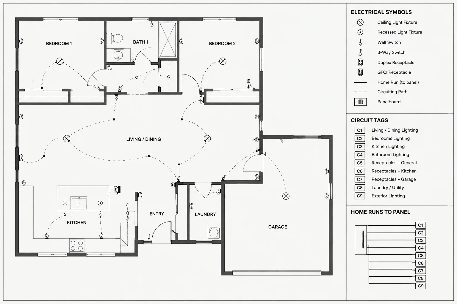
- Device and fixture symbols
- Panel, transformer, disconnect, and equipment tags
- Circuit numbers and home-run notes
- Keynotes and general callouts
- Dimensions and leaders
- Room or area labels used for electrical coordination
- Match lines, section markers, and detail references
- Linetype patterns and symbol linework
The objective is not to make every object the same size. The objective is to give each class of information a predictable visual role when it appears on the sheet.
Start by classifying CAD content
Before adjusting scales, divide drawing content into three practical categories. Each category should be handled differently.
| Content category | Typical examples | Scaling approach |
|---|---|---|
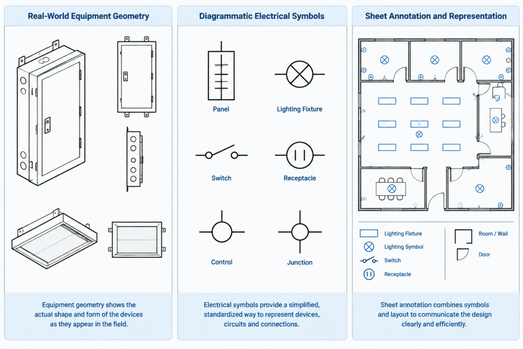
| Real-world geometry | Equipment footprints, room boundaries, clearances shown for coordination, cable tray paths | Draw at actual project size and display through a scaled viewport |
| Diagrammatic symbols | Receptacles, switches, detectors, home-run arrows, connection symbols | Size for communication and plotted readability rather than physical dimensions |
| Sheet annotation | Text, leaders, tags, dimensions, detail references | Control by the intended sheet appearance using the office CAD method |
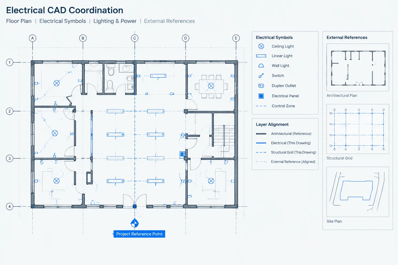
This classification prevents a common error: treating every electrical block as though it represents a physical footprint. A receptacle symbol on a power plan is normally a graphic identifier. A floor-standing enclosure shown in an electrical room layout may need an accurate plan footprint. Both may be CAD blocks, but they serve different purposes.
Coordinate model space, sheets, and viewports
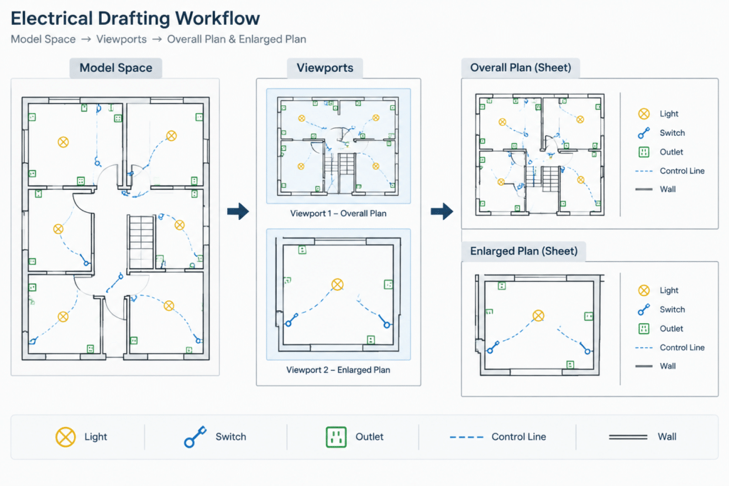
A common workflow keeps project geometry in model space and assembles sheets in paper space or another sheet environment. Viewports then present selected areas of the model at appropriate scales. Regardless of software, the underlying drafting logic should remain consistent.
Keep physical geometry stable
Walls, equipment outlines, routing paths, and other measurable objects should not be resized merely to make a sheet look better. Instead, select a suitable viewport scale or create an enlarged view. Altering physical geometry for graphic convenience can create conflicts between plans, schedules, details, and coordination models.
Choose the view scale before final annotation
Preliminary notes can be placed early, but annotation should be reviewed after the sheet view and viewport scale are established. A tag that looks reasonable while editing the full model may overlap nearby devices once viewed on the sheet. Conversely, text created for an enlarged plan may appear oversized if reused in an overall plan without scale control.
Lock approved viewport settings
After a view has been composed and checked, protect its scale and position using the controls available in the CAD platform. Accidental viewport changes can affect text appearance, linetype display, detail boundaries, and the amount of model geometry visible on the sheet.
Select one annotation strategy
Electrical CAD teams generally use one of several approaches. The important issue is not which method is universally best, but whether the selected method is documented and applied consistently.
Annotative or scale-aware objects
Where supported, scale-aware text, dimensions, leaders, and blocks can display at a controlled sheet size in multiple viewport scales. This can be efficient when the same plan information must appear in both an overall view and an enlarged view.
However, scale-aware objects require disciplined management. An object may be visible in one view and absent in another if its assigned scales are incomplete. Teams should confirm visibility from the finished sheet rather than relying only on model-space editing.
Fixed model-space scaling
Some offices use separate text styles, dimension styles, or block scales for each drawing scale. This method can be predictable, especially in established templates, but users must select the correct style and scale factor for each view. Copying annotation between views without adjustment is a frequent source of inconsistency.
Paper-space annotation
Placing notes and callouts directly on the sheet can provide straightforward control over plotted appearance. It is useful for sheet-specific information, such as a title or a callout that applies only to one viewport. It may be less suitable for annotations that must move with model geometry or appear on several sheets.
A hybrid workflow is often practical: keep design-related tags with the model, and reserve sheet space for sheet-specific references. The project CAD plan should define the boundary between the two.
Manage electrical symbols at different scales
Electrical symbols must remain recognizable without obscuring the background. This becomes challenging when dense device layouts appear on small-scale plans.
Do not enlarge every symbol automatically
If symbols overlap, first determine whether the view is trying to communicate too much. An enlarged plan, partial plan, or dedicated system plan may be clearer than forcing oversized graphics into the original view.
Create purpose-based symbol variants
A symbol library can include coordinated variants for overall plans, enlarged plans, and diagrams. Variants should preserve the same basic identity while adjusting secondary linework or annotation density. Use clear block names so drafters can distinguish the intended application.
Separate symbols from footprints
When equipment location and physical size matter, show the equipment footprint on an appropriate layer and use a separate tag or symbol to identify it. This allows the footprint to remain dimensionally meaningful while the identifier stays readable.
Review mirrored and rotated blocks
Symbols placed along walls or equipment faces are frequently rotated or mirrored. Confirm that embedded text, attributes, polarity indicators, and directional marks remain readable and retain their intended meaning after transformation.
Keep tags and leaders under control
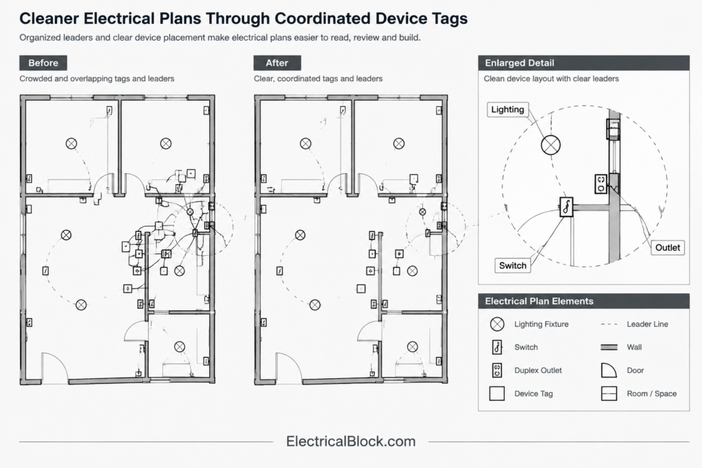
Tags should be positioned according to a repeatable hierarchy. Place the identifier close enough to establish a clear relationship, but avoid covering architectural features or other electrical information. Use leaders when proximity alone does not make the association clear.
For dense plans, consider the following sequence:
- Place the primary device or equipment symbol.
- Add the identifying tag using the project annotation method.
- Check for conflicts with circuiting, dimensions, and room information.
- Move the tag before introducing a leader.
- Add a leader only when it improves identification.
- Check the result in the sheet viewport and in a test plot or PDF.
A leader should terminate unambiguously. Avoid crossing unrelated circuit lines, pointing between two similar devices, or using excessively long routes that force the reader to search for the referenced object.
Coordinate enlarged plans with overall plans
An enlarged plan is not simply a larger copy. It should clarify information that cannot be communicated cleanly in the overall view. Define what remains on the overall plan and what moves to the enlargement.
The overall plan may retain major equipment, distribution relationships, and an enlargement reference. The enlarged view can show detailed device locations, equipment tags, local dimensions, and coordination notes. Avoid duplicating editable information in two places unless the workflow includes a deliberate method for keeping it synchronized.
Use consistent identifiers across both views. A panel, disconnect, or control station should not acquire a different tag merely because it appears at another scale. If a simplified symbol is used on the overall plan, it should still relate clearly to the detailed representation.
Check linetypes and lineweights with annotation
Annotation readability depends on more than text height. Dense symbols can become solid blobs if internal linework is too heavy. Dashed circuit lines may appear continuous or fragmented if linetype scaling is not coordinated with the viewport. Leaders may disappear if their lineweight is too light relative to the background.
Evaluate the combined hierarchy on the finished sheet:
- Primary electrical symbols should be easy to locate.
- Tags should be readable without dominating the plan.
- Circuiting should connect devices clearly but remain secondary to equipment identification.
- Architectural backgrounds should provide context without competing with electrical content.
- Detail boundaries and references should stand out as navigation aids.
Use a sheet-based quality-control review
Model space is an editing environment; the sheet is the deliverable. Complete the annotation review from layouts or exported sheets at the expected viewing condition.
- Confirm every viewport uses its intended scale.
- Check that scale-aware objects appear in all required views.
- Look for symbol, tag, and leader overlaps.
- Verify that equipment footprints have not been resized for appearance.
- Confirm rotated and mirrored attributes remain legible.
- Compare repeated symbols across sheets for consistent appearance.
- Check detail and enlargement references in both directions.
- Review monochrome or project-standard plotting, not only CAD screen colors.
- Confirm that revisions have not displaced tags from their associated objects.
Build scale behavior into the CAD library
A useful electrical block library should communicate more than symbol shape. Block names, layer assignments, insertion points, attributes, and intended view types should support predictable placement. Library documentation can identify whether an item represents a true footprint, a diagrammatic plan symbol, or a schematic symbol.
Do not assume a downloaded block is ready for direct project use. Inspect its units, base point, layers, text objects, attribute behavior, and plotted appearance. Compare it with the project template and drafting conventions before incorporating it into a live drawing set.
Consistent electrical CAD annotation scales come from coordinated decisions rather than last-minute resizing. When physical geometry remains accurate, symbols are treated according to their purpose, and annotation is reviewed on the final sheet, drawings become easier to navigate and less vulnerable to scale-related errors.
Turn annotation decisions into an office workflow
Scale-related problems are easier to prevent when the project team makes annotation decisions before sheets become crowded. The workflow should identify which content belongs with model geometry, which content is sheet-specific, and which symbols require alternate representations for different view types.
Define ownership of each annotation type
Assign a consistent location and editing method to each class of information. For example, a device identifier may need to remain associated with its model-space symbol, while a sheet navigation note may belong only to the layout. Clear ownership reduces duplicated notes and helps prevent annotations from becoming detached during revisions.
Document library behavior
Block library notes should state whether a block is a diagrammatic symbol, an equipment footprint, or a combined graphic. They should also identify whether attributes are intended to rotate with the block, remain readable relative to the sheet, or appear only in selected views. This information is more useful than relying on block names alone.
Use a representative sheet for early testing
Before applying a method throughout the drawing set, test it on a sheet containing a realistic mix of symbols, tags, circuiting, background information, and references. Review the result using the intended plot style. A clean isolated symbol does not reveal how the same graphic will perform in a crowded plan.
Diagnose annotation problems before resizing objects
- Text appears inconsistent between views: Check the annotation method, assigned scales, text style, and viewport settings before manually changing text objects.
- Symbols cover nearby geometry: Decide whether the plan needs a simplified symbol, reduced information density, or an enlarged view.
- Tags drift away after revisions: Review insertion points, associative behavior, grouping practices, and whether the tag should remain with model content.
- Some annotations disappear: Check viewport layer controls, scale-aware visibility, object layers, and plotting status.
- A footprint looks readable but inaccurate: Restore the physical geometry and use a separate identifier or diagrammatic overlay for graphic clarity.
- Leaders become difficult to follow: Reposition tags, reduce crossings, and confirm that each leader terminates at one unmistakable object.
Record the final drafting convention
Once the team approves the approach, record it in the project CAD plan or template documentation. Include the chosen annotation strategy, the division between model and sheet annotation, symbol variant naming, layer expectations, and the required sheet-based review. A documented convention helps later contributors reproduce the same visual result without relying on manual correction.
Frequently asked questions
What is the purpose of an electrical CAD annotation scale?
It controls how communication graphics relate to their intended sheet appearance. The goal is to keep text, symbols, tags, dimensions, and callouts legible while leaving measurable project geometry at its actual modeled size.
Should electrical symbols represent their physical size?
Not always. Many plan symbols are diagrammatic identifiers sized for recognition. Equipment footprints and other coordination geometry may need to represent actual project dimensions. The drawing should distinguish between these purposes.
Can the same symbol be used in an overall plan and an enlarged plan?
It can, provided the symbol remains readable and does not obscure surrounding information. Scale-aware behavior or coordinated symbol variants may be more effective when the views require different levels of graphic detail.
Why does annotation look correct in model space but fail on the sheet?
Model-space editing does not always show the final combination of viewport scale, layer visibility, plotted lineweight, linetype display, and surrounding sheet content. Annotation should therefore be checked from the layout and exported deliverable.
When is paper-space annotation appropriate?
It is useful for information that applies specifically to a sheet or viewport. Annotation that must follow model geometry, remain coordinated with an object, or appear in several views may be better managed with the model or another coordinated documentation method.
How should downloaded electrical CAD blocks be checked?
Review the block’s units, insertion point, layers, attributes, text behavior, linework, and plotted appearance. Determine whether it represents a physical footprint or a diagrammatic symbol before adding it to the project library.


Leave a Reply
You must be logged in to post a comment.