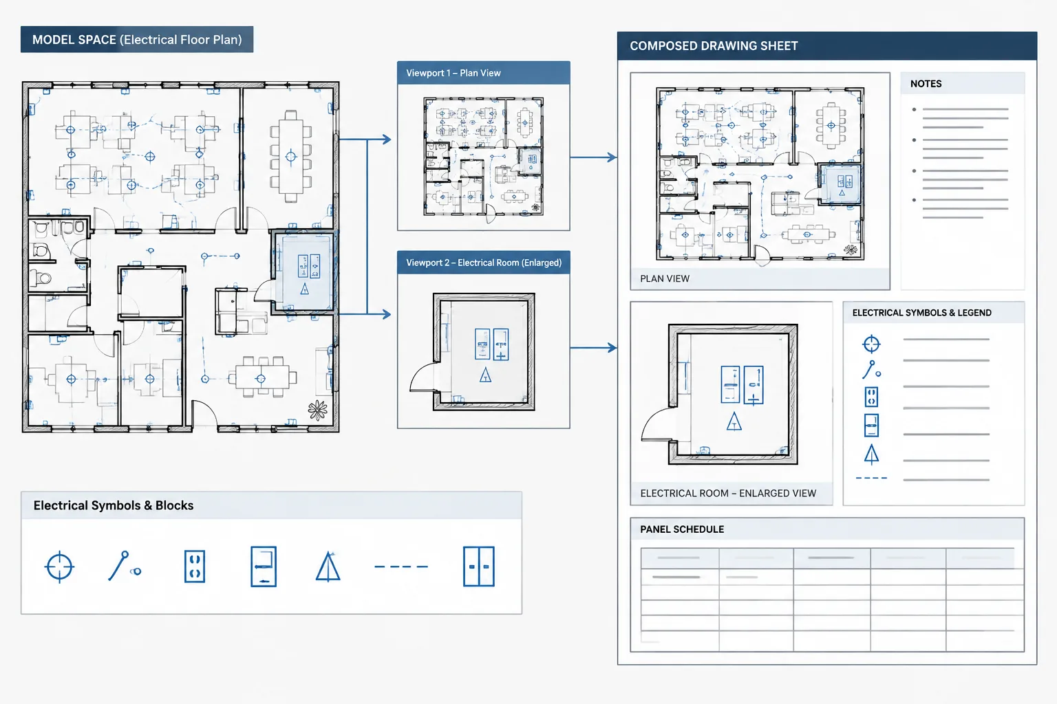
Electrical CAD sheet setup establishes the relationship between coordinated design geometry and the final drawing page. A disciplined setup keeps electrical devices, circuit graphics, equipment layouts, notes, and referenced backgrounds aligned while allowing each sheet to present only the information needed for its purpose.
The guidance below provides a software-neutral framework for organizing model space, composing paper-space layouts, and managing viewports. It is intended for drafting and documentation workflows; project-specific CAD standards, plotting requirements, and review procedures remain controlling.
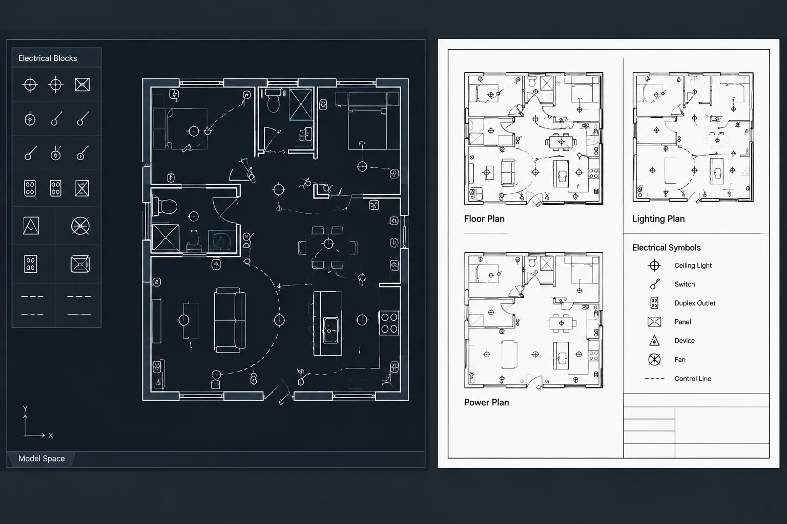
A reliable electrical CAD sheet is more than a border placed around a floor plan. It is a controlled view of design information, assembled so that symbols, notes, references, and background geometry remain readable at the intended plotted size. When model space, paper space, and viewports are used consistently, the same coordinated electrical model can support overall plans, enlarged plans, routing views, and coordination sheets without unnecessary duplication.
This guide explains a practical electrical CAD sheet setup workflow. The focus is drawing organization and documentation rather than software-specific commands. Exact sheet sizes, scales, title-block fields, and file structures should always follow the project requirements and the organization responsible for issuing the drawings.
Understand the Role of Each Drawing Environment
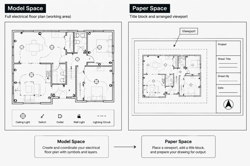
Most general-purpose CAD workflows separate design geometry from sheet presentation. The terminology may vary between platforms, but the underlying distinction is important.
Model space contains project geometry
Model space is generally where the building background, electrical devices, equipment footprints, circuit graphics, raceway routes, and coordination information are drawn. Geometry should represent the project at its actual design size rather than being resized to fit a sheet.
For an electrical plan, model-space content may include:
- Architectural backgrounds and structural references
- Lighting fixtures, receptacles, switches, panels, and equipment
- Circuit lines, home-run graphics, and routing information
- Equipment clearances or coordination zones when required
- Room names, device tags, and selected plan annotations
- Match-line geometry and enlarged-plan boundaries
Paper space organizes the issued sheet
Paper space, sometimes called a layout or sheet environment, represents the plotted page. It typically contains the title block, sheet identification, issue information, general sheet notes, graphic scales where appropriate, and viewports that show selected portions of the model.
Paper space is useful because it separates page composition from design geometry. Moving a viewport on a sheet changes the presentation, not the physical location of the electrical devices in the model.
Viewports connect the sheet to the model
A viewport is a controlled window from paper space into model space. Each viewport can show a selected area at an assigned scale and can apply view-specific layer visibility where the CAD platform and project workflow permit it.
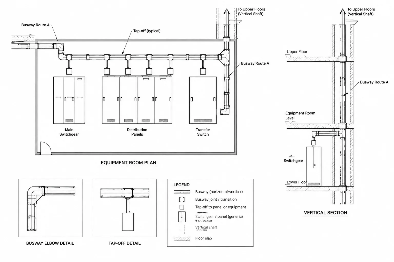
This makes it possible to show the same coordinated geometry in different ways. An overall power plan might display device locations and circuiting, while an enlarged electrical-room plan shows the same equipment with additional tags and coordination details.
Start with the Required Sheet Purpose
Before creating viewports, define what the sheet must communicate. A sheet should have a clear documentation role rather than becoming a collection of available information.
Common electrical sheet purposes include:
- Overall lighting or power plans
- Enlarged equipment-room plans
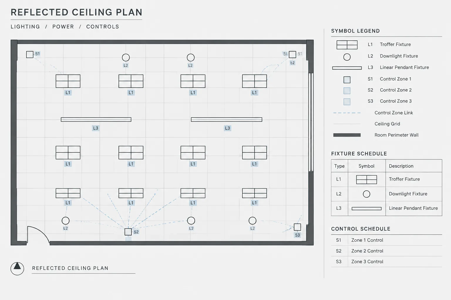
- Ceiling coordination views
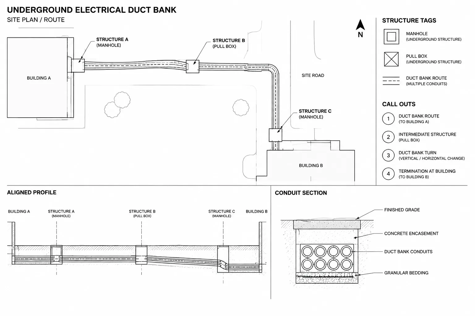
- Raceway or cable tray routing plans
- Site electrical plans
- Diagram, schedule, and detail sheets
- Combined plans used for internal coordination
The intended purpose influences viewport coverage, annotation density, layer visibility, and the amount of background information shown. A permit or construction sheet may need a different visual hierarchy from an internal coordination sheet, even when both reference the same model geometry.
Build a Stable Model-Space Foundation
A sheet workflow cannot compensate for poorly controlled model geometry. Before laying out sheets, confirm that the electrical work and referenced backgrounds share the expected coordinate system, insertion point, orientation, and drawing units.
Keep geometry at project coordinates
Avoid moving copied floor plans simply to center them inside individual sheets. Multiple displaced copies make coordination difficult and can separate symbols from the architectural rooms or equipment they are intended to serve. Use viewports to frame the required area instead.
Separate content by function
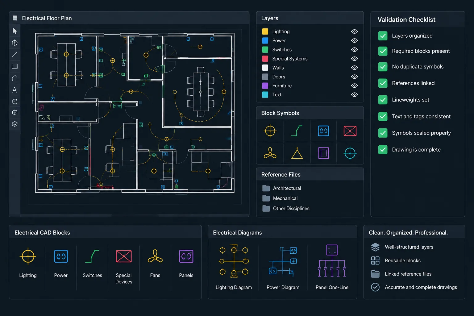
Layer organization should allow the drafter to distinguish electrical systems, annotations, references, and temporary coordination graphics. Layer names vary by office and project, but useful functional groups often include:
- Lighting devices and lighting circuiting
- Power devices and power circuiting
- Distribution equipment
- Raceways, cable trays, and related tags
- Text, dimensions, leaders, and match lines
- Architectural or consultant references
- Nonplot construction and coordination graphics
Do not rely only on color to separate information. Layer identity, linetype, lineweight, symbol form, and plotted hierarchy should work together.
Create Viewports Deliberately
Each viewport should have a defined boundary, scale, center point, and visibility state. Treat these properties as part of the sheet setup rather than incidental drafting settings.
Choose scale from communication needs
Select a scale that keeps electrical symbols and annotations legible while showing enough surrounding context to locate the work. Dense electrical rooms, equipment yards, and congested ceiling areas may require enlarged views. Open or repetitive areas may be understandable in a broader plan.
Do not enlarge a view merely to fill unused sheet space. The chosen scale should support consistent interpretation across related sheets.
Set the view, then protect it
After framing the correct model area and confirming the viewport scale, protect or lock the view using the controls available in the CAD platform. This reduces accidental zooming or panning during later editing.

A useful viewport check includes:
- Correct floor or project area
- Expected orientation
- Assigned scale
- Suitable crop boundary
- Correct layer visibility
- No unintended geometry outside the required view
Use irregular boundaries sparingly
Nonrectangular viewport boundaries can help fit a plan around schedules or notes, but complicated shapes can make sheets harder to maintain. A simple boundary is usually easier to review, align, and revise. If a view requires a highly irregular crop, reconsider the sheet arrangement or use a clearly referenced enlarged plan.
Decide Where Annotations Belong
Annotation placement is one of the most important electrical CAD sheet setup decisions. Offices commonly use model-space annotation, paper-space annotation, or a controlled combination of both.
| Annotation type | Typical placement consideration |
|---|---|
| Device and equipment tags | Often tied closely to model geometry so they remain associated with the item |
| Room-specific circuit notes | May be placed with the plan when they must follow a particular area |
| Sheet title and view title | Usually belongs to the sheet presentation |
| General notes | Usually placed on the sheet unless they apply graphically to a model location |
| Match-line references | Must coordinate with model boundaries and the destination sheet reference |
| Revision clouds and issue marks | Placement should follow the project revision workflow and clearly identify the changed content |
The best approach is the one applied consistently across the drawing set. Mixing methods without a clear rule can produce duplicated notes, incorrect text sizes, and annotations that disappear when viewport scales or layer states change.
Control View-Specific Layer Visibility
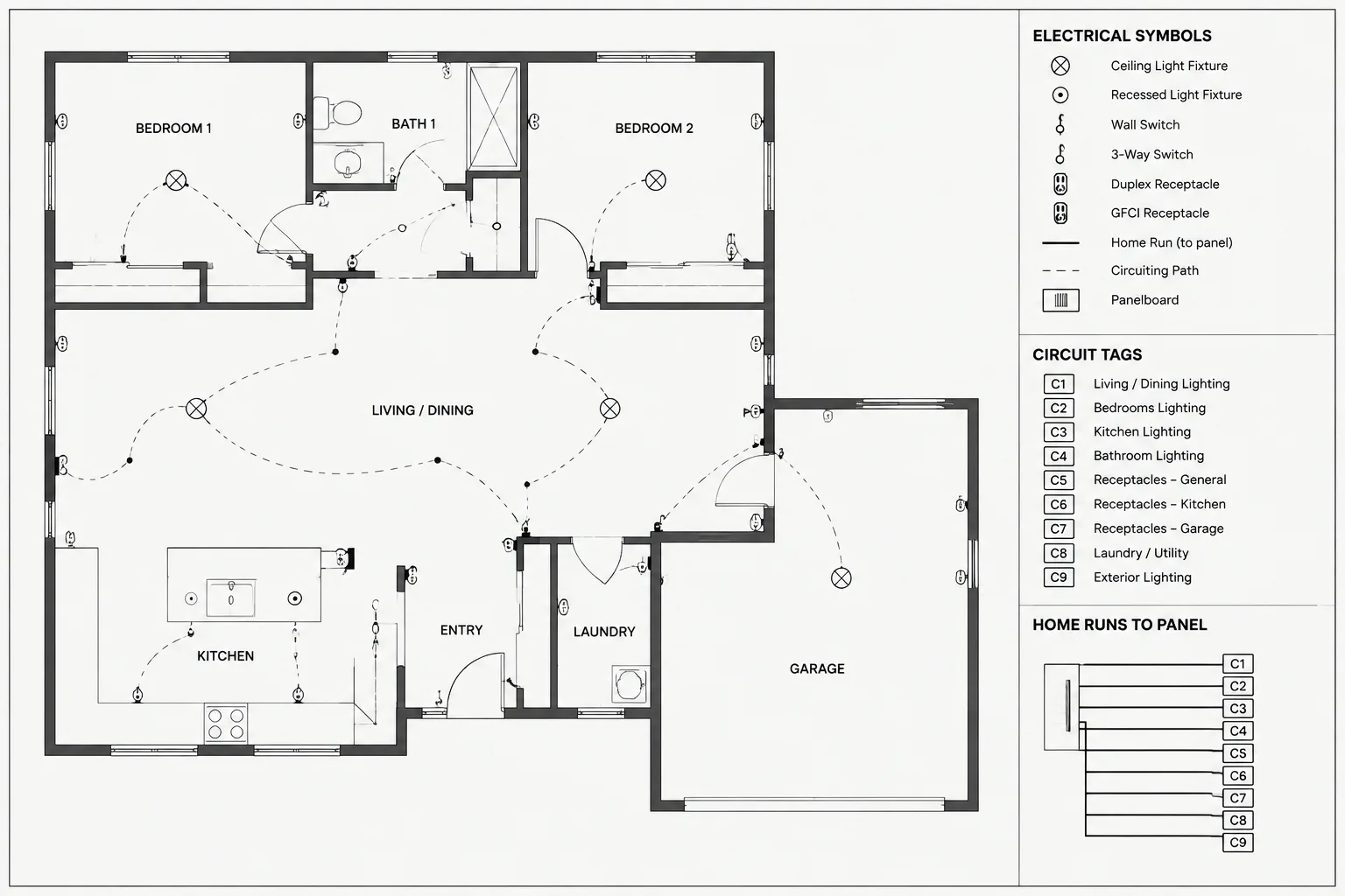
Viewport-specific layer control can make one model serve several documentation purposes. For example, an overall power plan may suppress lighting circuit graphics, while a lighting plan suppresses receptacle circuiting. An enlarged room plan may display equipment clearance graphics that are unnecessary on the overall floor plan.
Use this capability carefully. Excessive viewport exceptions can make troubleshooting difficult because a layer may appear in model space but remain hidden in only one sheet view. Maintain a clear record of intentional overrides and review them whenever the base layer structure changes.
Before issuing a sheet, compare viewport visibility against the sheet purpose. Confirm that hidden layers are truly irrelevant and that required tags, circuit lines, equipment, and backgrounds have not been suppressed accidentally.
Coordinate Enlarged Plans and Match Lines
When a floor plan is divided across sheets or supplemented with enlarged views, the relationships between views must be explicit. Match lines should identify where coverage continues, and references should direct the reader to the correct destination view or sheet.
For enlarged plans, verify that:
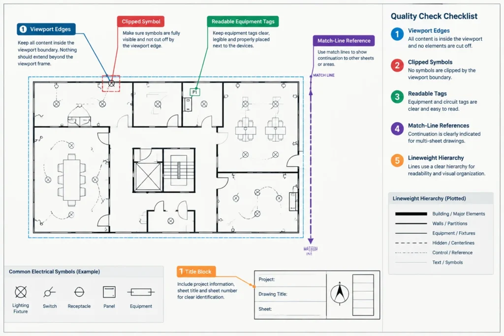
- The enlarged area can be located on the overall plan
- The view title describes the area clearly
- Equipment and device tags agree between views
- Duplicate annotations do not conflict
- Continuation graphics align across adjacent views
- The architectural background represents the same coordination state
If the overall and enlarged views intentionally show different levels of information, use a consistent rule. For example, an overall plan might show equipment location and feeder intent, while the enlarged view carries detailed device tags and routing. The reader should not have to guess which view governs.
Keep Title Blocks and Sheet Data Maintainable
Title blocks should contain controlled project and sheet information rather than manually repeated text wherever possible. Fields may include project identification, sheet title, sheet number, issue status, dates, drawn-by information, checked-by information, and revision data, depending on the organization’s requirements.
Use a consistent title-block source throughout the project. Unmanaged copies can drift apart, causing outdated project names, inconsistent issue information, or misplaced revision entries. Any automated attributes or fields should still be checked in the plotted output.
Review the Plotted Sheet, Not Just the CAD View
A drawing that looks clear on a monitor may become confusing when plotted or exported. Final review should evaluate the actual sheet presentation.
Check the following:
- Electrical symbols remain distinguishable from the background
- Text, leaders, and tags are readable without crowding
- Viewport boundaries do not plot unless intentionally shown
- Lineweights create a useful visual hierarchy
- Dashed and hidden linetypes remain interpretable
- View titles, scales, and references match the displayed content
- No notes, symbols, or routes are clipped at viewport edges
- Title-block and revision information is complete for the issue
Also inspect sheets together as a set. A single plan may look correct while still conflicting with the sheet index, adjacent floor plan, enlarged view, panel documentation, or single-line diagram.
A Practical Sheet Setup Sequence
A repeatable workflow reduces rework and makes peer review easier:
- Confirm the drawing units, coordinates, orientation, and reference files.
- Organize electrical model geometry using the project layer structure.
- Define the purpose and coverage of each sheet.
- Insert or reference the approved project title block.
- Create viewports for the required model areas.
- Assign and verify each viewport scale.
- Apply only the layer visibility needed for that view.
- Add view titles, sheet notes, and cross-references.
- Protect stable viewport views against accidental changes.
- Plot or export a review copy and inspect it at sheet level.
- Coordinate the sheet with related plans, schedules, and diagrams.
Make the Sheet a Controlled View of One Coordinated Model
The central principle of electrical CAD sheet setup is simple: the model should hold coordinated project information, while the sheet should present an intentional view of that information. Viewports should not become substitutes for sound layer control, and paper space should not become a second disconnected design model.
When responsibilities are clearly divided among model space, paper space, and viewports, electrical drawings become easier to revise, compare, plot, and quality-check. This structure also makes CAD blocks more useful because symbols can remain at coordinated model locations while appearing appropriately in overall plans, enlarged views, and specialized electrical sheets.
Use Sheet Setup as a Quality-Control System
Model space, paper space, and viewports are not merely separate CAD work areas. Together, they form a documentation control system. Model space establishes where project information belongs, paper space defines how a drawing is presented, and each viewport records which portion of the model the reader needs to see.
This distinction helps reviewers diagnose drawing problems. If a device is misplaced relative to the building background, the issue is likely in the model or its references. If the correct device is missing from only one sheet, viewport visibility or cropping may be responsible. If a title, general note, or issue entry is incorrect, the sheet layout should be reviewed.
Separate Model Problems from Presentation Problems
Before editing geometry, identify whether the problem exists throughout the coordinated model or only in a particular layout. Moving electrical objects to solve a sheet-composition problem can create conflicts in other views. Likewise, changing shared layers to correct one viewport can unintentionally affect several sheets.
- Model issue: incorrect location, orientation, reference alignment, or system assignment.
- Viewport issue: incorrect crop, view position, scale, orientation, or visibility state.
- Paper-space issue: incorrect sheet note, title, reference, border information, or page arrangement.
- Plot issue: unexpected lineweight, linetype, clipping, screening, or output behavior.
Document Intentional Exceptions
Some electrical sheets require visibility settings or annotations that differ from the rest of the drawing set. These exceptions should be intentional and reviewable. A viewport that hides coordination graphics may be correct, but a reviewer needs a reliable way to distinguish that decision from an accidental layer override.
Consistent naming, sheet notes, view titles, layer practices, and internal review comments make exceptions easier to maintain. The goal is not to make every view identical; it is to make differences understandable.
Check Relationships Across the Drawing Set
A well-composed sheet can still be wrong if its information conflicts with related documentation. During review, compare plan views with enlarged plans, schedules, equipment references, diagrams, continuation areas, and adjacent sheets. Tags and references should lead the reader to the intended information without creating competing instructions.
This set-level review is especially important after background updates, sheet rearrangement, or changes to viewport coverage. A revision that appears local may affect match lines, view titles, continuation references, and annotation placement elsewhere.
Frequently Asked Questions
Should electrical geometry be drawn in paper space?
Project geometry is generally better maintained in model space so devices, equipment, routing, and backgrounds remain coordinated. Paper space is normally used for sheet composition, title-block information, sheet-level notes, and controlled views of the model. The project CAD standard should determine any exceptions.
Why does an electrical layer appear in model space but not in a viewport?
The layer may have a view-specific visibility setting, or the geometry may fall outside the viewport boundary. Also review reference visibility, annotation behavior, and the viewport’s intended sheet purpose before changing the shared model.
When should an enlarged electrical plan be used?
An enlarged plan is useful when an overall view cannot clearly communicate equipment, device tags, routing, coordination zones, or annotations. The enlarged view should be referenced from the overall plan and coordinated with the same underlying project geometry.
Why should a completed viewport be protected?
Protecting a stable viewport reduces the chance of accidental zooming or panning during later sheet edits. The view should still be checked after model updates, reference changes, and revisions to sheet coverage.
Should annotation be placed in model space or paper space?
Either approach can work when governed by a consistent project rule. Annotations closely associated with devices or model locations are often maintained with the plan, while sheet titles and general sheet notes typically belong to the layout. Uncontrolled mixing can create duplicate notes and inconsistent presentation.
What should be reviewed before issuing an electrical CAD sheet?
Review the plotted or exported sheet for readable symbols and text, correct viewport coverage, intentional layer visibility, unclipped information, coordinated references, suitable visual hierarchy, and complete sheet data. Related plans, schedules, and diagrams should also be compared for consistency.






Leave a Reply
You must be logged in to post a comment.