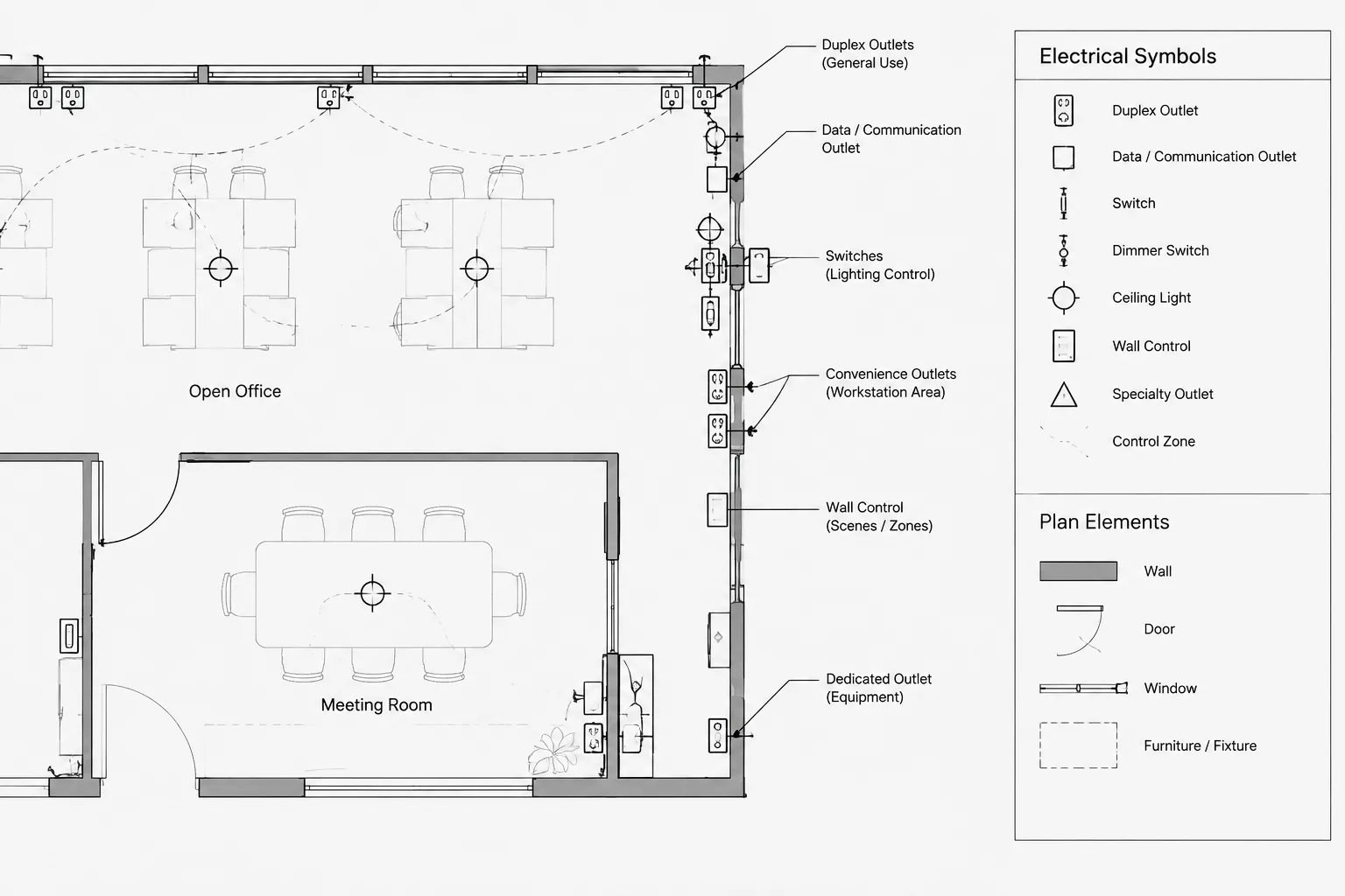
Crowded electrical plans require more than smaller symbols or additional annotation. A readable drawing must distinguish the intended installation location from the graphic position used for presentation. This guide explains how offsets, leaders, grouping, anchor points, layers, and enlarged views can preserve that relationship without obscuring design intent.
Electrical symbols are graphic references, not physical equipment footprints. That distinction becomes important when a floor plan contains closely spaced receptacles, switches, sensors, lighting controls, connection points, and equipment tags. Placing every symbol directly over its intended location may produce an unreadable cluster, but moving symbols without explanation can misrepresent the design.
Good electrical symbol placement in CAD balances three needs: showing design intent, maintaining a clear relationship to the architectural background, and producing a drawing that remains readable when plotted. The goal is not simply to make symbols fit. The goal is to communicate which device belongs where, what it serves, and how reviewers should interpret any graphic displacement.
Why Electrical Symbols Become Crowded
Electrical plans often combine information from several systems on one view. A wall segment may contain power outlets, data outlets, switches, control stations, and connections for nearby equipment. Ceiling plans can become equally dense where luminaires, sensors, diffusers, access panels, and architectural features compete for space.
Common causes of symbol congestion include:
- Multiple devices installed at the same wall location or within the same equipment zone.
- Large annotation symbols placed over small architectural spaces.
- Tags, circuit references, mounting notes, and keynote references attached to one device.
- Electrical elements located near doors, millwork, casework, columns, or equipment outlines.
- Several disciplines using the same area for their own symbols and annotations.
- Plans shown at a scale that cannot comfortably display the required information.
Reducing symbol size indiscriminately is rarely a complete solution. Symbols and text must remain recognizable in the final issued format, including plotted sheets and review PDFs.
Separate Physical Location from Graphic Location
A physical location represents where a device or connection is intended to be installed. A graphic location is where its symbol is placed so the drawing can be read. These locations may coincide, but they do not always have to.
When a symbol is displaced, the drawing should provide a clear visual relationship back to the intended location. That relationship may be established with a leader, extension line, dimension, aligned device group, mounting reference, or enlarged plan. The appropriate method depends on what the reader must understand.
| Drawing condition | Preferred drafting response | Main coordination concern |
|---|---|---|
| Single device with open drawing space | Place the symbol at or immediately adjacent to the intended location | Avoid unnecessary leaders or notes |
| Several devices at one wall location | Arrange symbols as a readable group and identify the common location | Preserve device quantity and grouping intent |
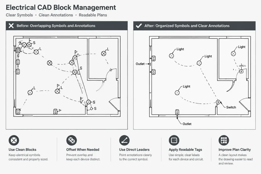
| Symbol conflicts with text or geometry | Offset the symbol and use a short, unambiguous leader | Prevent the leader from pointing to the wrong object |
| Dense room or equipment area | Create an enlarged plan or detail reference | Keep information coordinated between views |
| Device location depends on equipment | Reference the equipment outline, connection point, or coordinated mounting note | Avoid implying a final location before equipment coordination |
Choose a Consistent Symbol Anchor Point
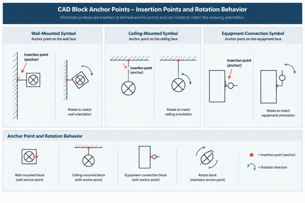
Every reusable CAD block should have a deliberate insertion point. For a wall-mounted device symbol, the anchor might represent the point where the device meets the wall. For a ceiling device, it may represent the symbol center. For equipment connections, it may represent the documented connection point rather than the center of the equipment outline.
Consistent anchor points make symbols easier to place, align, rotate, and verify. They also reduce uncertainty when another drafter edits the plan. A block with an arbitrary insertion point may look acceptable in one drawing but become difficult to snap, mirror, or replace accurately.
Before adding a block to a project library, verify:
- What physical or diagrammatic point the insertion point represents.
- Whether the symbol rotates correctly around that point.
- Whether attached attributes remain readable after rotation.
- Whether the block geometry is drawn consistently with the project’s symbol convention.
- Whether the symbol is intended for plans, diagrams, details, or another specific drawing type.
Use Leaders Only When They Clarify Intent
A leader should create a clear connection between an offset symbol or note and its subject. Excessive leaders can make a plan harder to follow, especially when lines cross circuiting, room boundaries, equipment outlines, or other annotations.
Keep leader paths direct
Use the shortest practical route that avoids unrelated objects. A reader should be able to follow the leader without deciding which of several nearby devices it identifies. Leader endpoints should terminate consistently at the symbol, location marker, or referenced object according to the project’s drafting convention.
Avoid crossing leaders
Crossed leaders create visual ambiguity. If two annotations must occupy the same area, rearrange the text, stack the device symbols, or move the notes to a clearer side of the plan. In especially dense conditions, an enlarged view is usually more effective than a web of leaders.
Do not use leaders to conceal unresolved coordination
Moving a symbol away from a conflict does not resolve the underlying physical issue. If a device appears to conflict with a door swing, cabinet, structural element, or another building service, flag the item for coordination rather than simply offsetting the symbol.
Arrange Multiple Devices as a Deliberate Group
When several electrical devices share a location, their symbols should read as one coordinated group rather than unrelated items scattered across the wall. Alignment and spacing can communicate grouping, but the project legend or notes must explain any convention that is not self-evident.
A grouped condition may need to show:
- The number and types of devices.
- Whether devices are combined at one location or merely nearby.
- Which tags, circuits, or control references apply to each device.
- Whether mounting relationships are shown diagrammatically rather than to physical scale.
- Whether final arrangement depends on architectural elevations or equipment requirements.
Do not rely on symbol proximity alone when different interpretations are possible. A concise note, device tag, elevation reference, or detail callout can prevent confusion.
Manage Tags and Circuit References Separately
Device symbols often become crowded because too much text is built into the block. Fixture types, circuit references, switch designations, panel references, mounting notes, and keynotes may all need different placement behavior.
Where practical, separate the symbol geometry from its annotations. This allows the drafter to reposition text without moving the device itself. Attributes can still support consistent data entry, but their display position should be adjustable where project workflows permit it.
Use a repeatable hierarchy:
- Keep the device symbol closest to the intended location.
- Place the primary device or type tag where it is easy to associate with the symbol.
- Place circuiting or source information consistently relative to similar devices.
- Move longer explanatory notes away from the device and connect them with a leader or keynote.
- Avoid repeating information already communicated clearly by the legend or schedule.
Know When to Create an Enlarged Plan
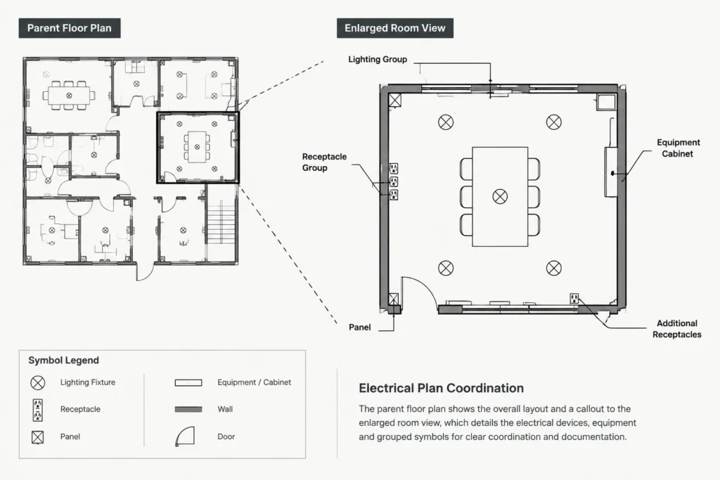
An enlarged plan is appropriate when offset symbols and leaders no longer provide a dependable picture of the design. Electrical rooms, equipment alcoves, service spaces, control areas, kitchens, laboratories, and densely furnished work areas are common candidates.
The parent plan should retain enough information to direct the reader to the enlarged view. The enlarged view should then become the primary location for detailed device placement, tags, routing, or equipment connections. Avoid fully duplicating the same annotation in both views unless the duplication has a clear coordination purpose.
When using an enlarged view, check that:
- The callout boundary contains the intended area.
- The detail or sheet reference is correct.
- Device tags match between related drawings.
- Changes made in one view are reflected in the other where required.
- The enlarged view uses the same background orientation or clearly indicates any rotation.
Control Visibility with Layers and View-Specific Information
Crowding is sometimes caused by displaying information that is not necessary for the current sheet. Sensible layer organization can separate device symbols, circuiting, tags, leaders, control information, existing work, and background references.
Layer control should improve presentation without hiding information that is essential to the drawing’s purpose. A symbol hidden on one plan may still require representation on another coordinated view. Document any sheet-specific visibility decisions so later revisions do not unintentionally remove required content.
Also review the architectural background. Furniture, hatch patterns, room data, and minor construction lines can overpower electrical symbols if the background is plotted with equal emphasis. A clear graphic hierarchy helps electrical content remain visible without erasing useful coordination context.
Check the Final Sheet, Not Just Model Space
A plan that looks clear while zoomed in may fail when viewed at sheet scale. Perform symbol-placement review in the actual viewport and in a plotted or exported test file. This reveals text collisions, heavy background lines, clipped leaders, unreadable attributes, and symbols that merge visually.
Practical quality-control questions
- Can each symbol be associated with one intended location?
- Are displaced symbols clearly connected to their physical locations?
- Could any leader be mistaken as pointing to another device?
- Are grouped devices clearly distinguished by type and quantity?
- Do tags and circuit references remain readable without covering plan geometry?
- Are symbols consistent with the project legend?
- Do enlarged views and parent plans agree?
- Are apparent physical conflicts identified for coordination rather than hidden graphically?
- Does the information remain legible in the final issue format?
A Readable Plan Still Requires Design Verification
Clear drafting does not establish code compliance, equipment suitability, or final constructability. Symbol placement should be verified against the project design criteria, architectural conditions, equipment information, applicable requirements, and the responsible design professional’s direction.
Well-managed electrical symbol placement makes that verification easier. By using consistent anchor points, controlled offsets, direct leaders, deliberate grouping, and enlarged views where needed, a CAD plan can remain readable without losing the relationship between the graphic symbol and the intended installation location.
A Practical Review Workflow for Crowded Plans
Review symbol placement as a communication task rather than an isolated graphic cleanup exercise. Begin by identifying which symbols represent direct locations, which have been displaced for clarity, and which depend on another drawing or coordinated reference. Every displaced item should have an unmistakable path back to its intended location.
Next, inspect repeated conditions. Similar device groups should use the same alignment, leader style, tag relationship, and annotation hierarchy throughout the drawing set. An isolated workaround may solve one collision while creating a convention that other team members cannot interpret consistently.
Complete the review in the issued sheet context. Check the viewport, background emphasis, visible layers, tags, callouts, and related details together. This helps reveal ambiguity that may not be apparent while editing individual blocks in model space.
Document Placement Conventions for Team Use
When a project uses recurring offsets or grouped-device arrangements, record the convention in the drawing legend, project drafting notes, or internal CAD guidance. The documentation should explain what the symbol anchor represents, how displaced symbols are connected to their locations, and where detailed placement information takes precedence.
Consistent conventions also improve revision work. A drafter reviewing a later change can distinguish an intentional offset from an accidentally moved block and can update related tags without disturbing the underlying device location.
Useful handoff checks
- Confirm that block insertion points represent a deliberate physical or diagrammatic reference.
- Identify symbols that were offset only for graphic clarity.
- Confirm that leaders, tags, and notes remain associated with the correct devices.
- Review related plans, elevations, details, legends, and schedules for matching design intent.
- Flag apparent physical conflicts for coordination instead of resolving them only through graphic displacement.
Frequently Asked Questions
Can an electrical symbol be moved away from its physical location?
Yes, when displacement improves readability and the drawing clearly connects the symbol to the intended location. A leader, extension line, grouped arrangement, mounting reference, or enlarged view may provide that connection.
When should a leader be added to an offset symbol?
Add a leader when the association would otherwise be uncertain. The path should be direct, avoid unrelated objects, and terminate according to the project drafting convention.
Should crowded electrical symbols simply be made smaller?
Not automatically. Smaller symbols may become difficult to recognize in the final sheet or review file. Repositioning annotations, controlling layers, grouping related devices, or creating an enlarged view may produce a clearer result.
How should several devices at one location be shown?
Arrange them as a deliberate group and preserve the device types, quantities, tags, and common-location relationship. Add a note, detail reference, or other identifier if proximity alone could be misinterpreted.
What is the difference between a symbol anchor and a leader endpoint?
The symbol anchor is the block insertion point that represents a chosen physical or diagrammatic reference. A leader endpoint is the graphic connection used to associate displaced information with its subject. They may relate to the same location, but they serve different drafting functions.
When is an enlarged electrical plan preferable?
Use an enlarged view when offsets, tags, and leaders can no longer communicate device relationships reliably. The parent plan should direct readers to the detailed view, and corresponding information should remain coordinated.










Leave a Reply
You must be logged in to post a comment.