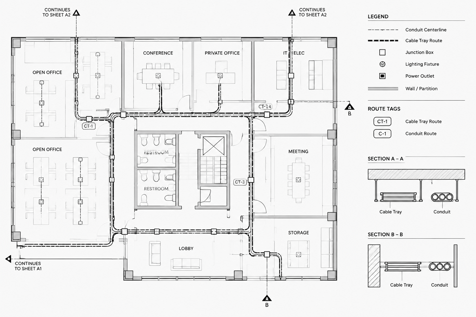
Clear conduit and cable tray routing plans help a project team understand where electrical pathways travel, how they continue between drawing areas, and where coordination requires closer review. Effective drafting combines readable route graphics with identifiers, vertical cues, schedules, and references to supporting views.
This guide focuses on documentation quality rather than field installation. Use it to develop or review routing plans while following the project CAD standard, design criteria, and discipline-specific requirements. Final pathway locations and construction details must be verified by the responsible project professionals.
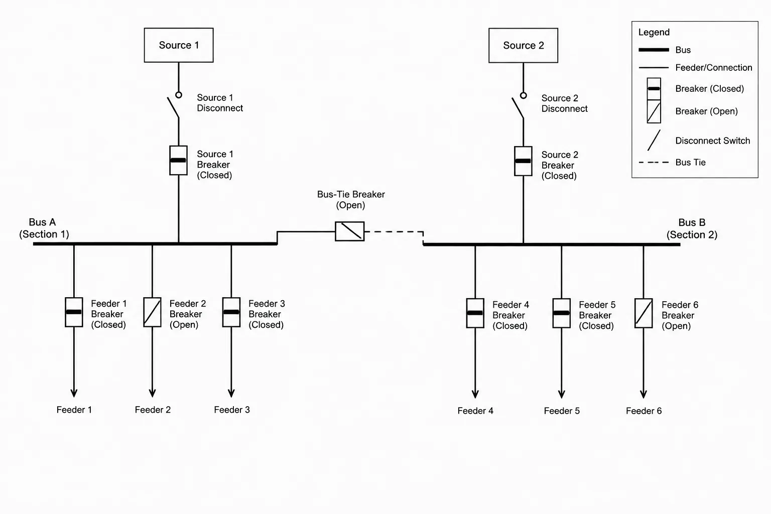
Conduit and cable tray routing plans translate an electrical distribution concept into coordinated drawing information. Unlike a single-line diagram, which explains electrical relationships, a routing plan shows where pathway systems are intended to pass through the building or site.
A useful routing drawing must communicate more than a line between two pieces of equipment. It should help readers identify the pathway type, understand changes in elevation, follow route continuations, distinguish crossings from connections, and coordinate the route with architectural, structural, mechanical, plumbing, and fire protection information.
The goal is not to reproduce every field decision in CAD. The goal is to document design intent at the level appropriate for the project while making unresolved conditions visible before drawings are issued.
Understand the Drawing Hierarchy
Conduit and cable tray information commonly appears across several related documents. Each view answers a different question:
- Single-line diagram: What equipment is electrically connected?
- Floor or site plan: Where does the pathway travel horizontally?
- Riser diagram: How does the pathway connect between levels or major vertical zones?
- Section or elevation: How is the route positioned vertically relative to nearby construction?
- Schedule: What identifier, service, origin, destination, or pathway description applies?
- Detail: What typical arrangement needs a larger drawing scale?
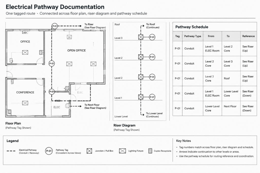
These documents should reinforce one another without duplicating all information. A plan may show a route tag and continuation reference, while a schedule carries the longer description. A section may clarify vertical stacking that would be difficult to understand from the plan alone.
Start with a Deliberate Route Classification
Before drawing pathways, decide how routes will be classified. Typical distinctions may include feeder pathways, branch-circuit pathways, communications pathways, control wiring pathways, life-safety systems, underground routes, and spare or future provisions.
The project team may represent these categories with separate layers, line types, colors, route tags, or combinations of those methods. Color can be helpful while editing, but issued drawings should remain understandable when printed or viewed without the original CAD color settings.
Avoid creating a unique graphic style for every circuit. Excessive variation makes plans difficult to manage. Group pathways according to information that genuinely affects coordination or interpretation.
Choose Linework That Explains the Route
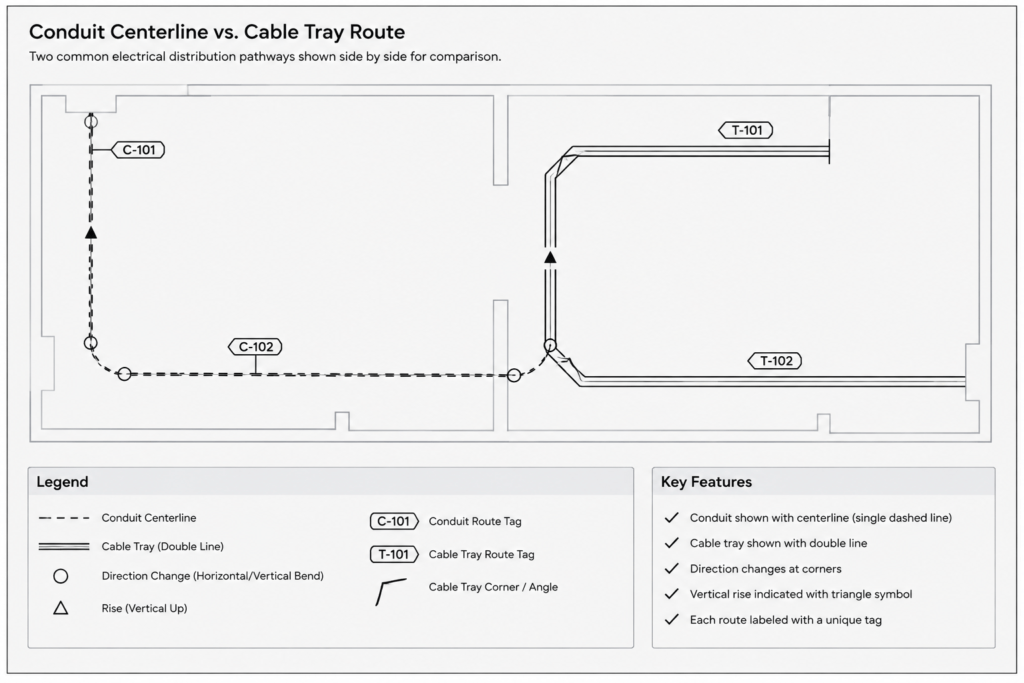
Pathway linework should be visually distinct from walls, equipment outlines, dimensions, and other building systems. The line should remain readable at the intended plotting scale without overpowering equipment symbols and annotations.
Conduit Representation
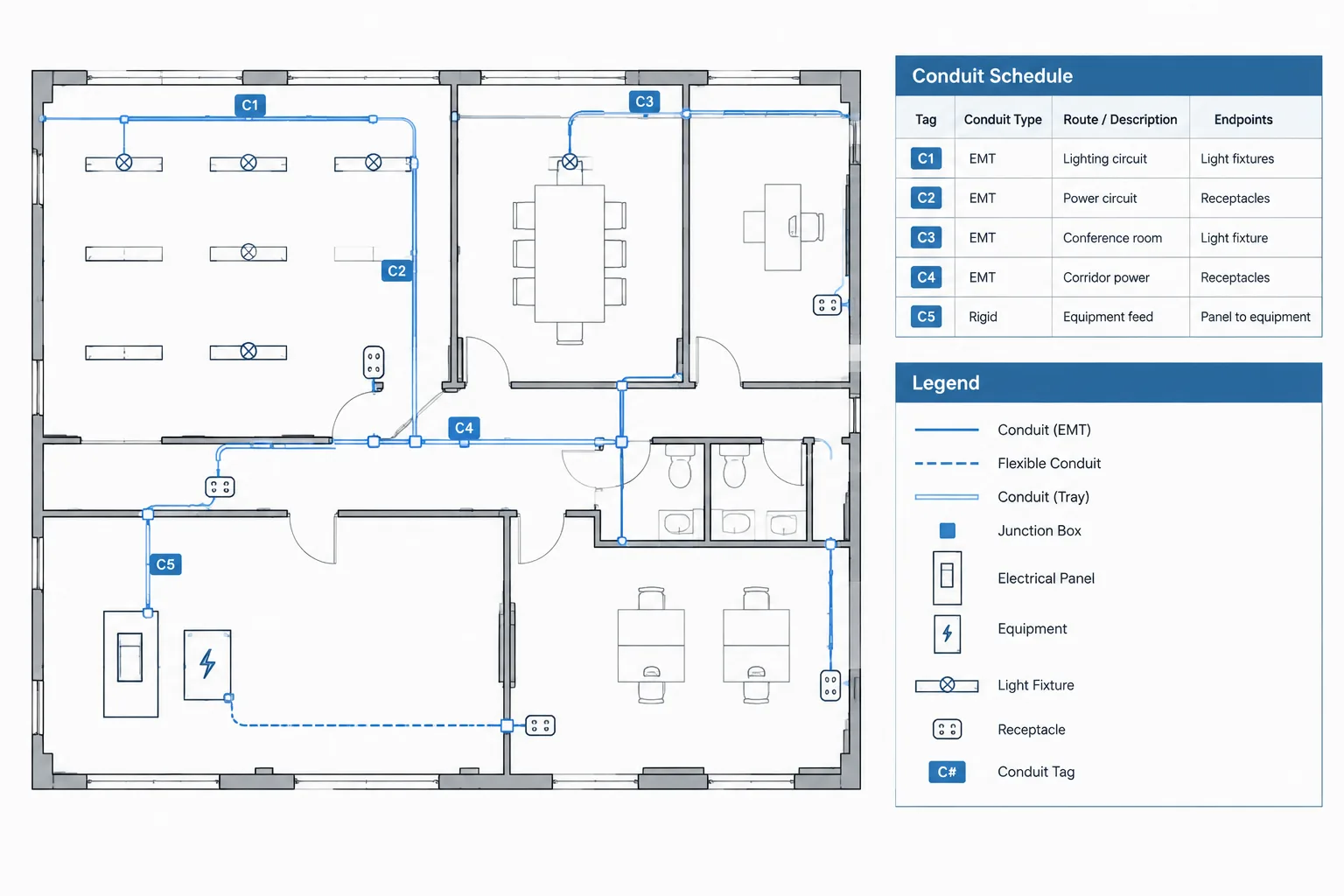
Conduit routes are often shown as simplified centerlines rather than physical-width outlines. This keeps the plan legible and communicates routing intent without implying that every bend or offset has been fully developed.
Parallel conduit runs can become cluttered when every pathway is drawn individually. Depending on the project documentation approach, a grouped route line with a clear tag may communicate the design more effectively. If individual lines are necessary, spacing should be sufficient to prevent them from merging when plotted.
Cable Tray Representation
Cable tray may be represented by a centerline, a double-line outline, or a simplified tray symbol. A double-line representation can help communicate the occupied routing zone, but it should not be mistaken for a verified installation envelope unless the route has been fully coordinated.
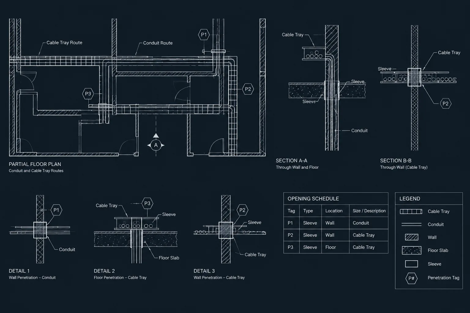
Use a consistent graphic treatment for tray fittings, direction changes, intersections, drops, and rises. When the plan scale cannot show these conditions clearly, reference an enlarged view or section.
Build a Route Tagging System
A route tag should connect plan graphics to supporting documentation. It does not need to contain every technical attribute directly on the floor plan. Compact tags generally produce cleaner drawings and reduce conflicts when information changes.
A practical tag structure may identify:
- The route or pathway designation
- The service or system category
- The origin and destination, when useful
- A schedule or detail reference
- Whether the route continues on another drawing
Use one identifier consistently across plans, risers, schedules, and details. Do not assign different names to the same route merely because it appears in several views. If a route changes designation at a defined transition point, show that transition explicitly.
Show Vertical Information, Not Just Horizontal Paths
A floor plan alone may make two crossing routes look connected even when they are at different elevations. It can also conceal conflicts above ceilings, below structure, or near equipment access zones.
Use elevation notes, rise and drop symbols, sections, or enlarged views where vertical position matters. The drafting method should answer three basic questions:
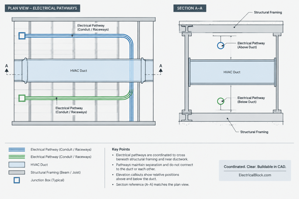
- Does the route pass above, below, or connect to the intersecting element?
- Does it change elevation at this location?
- Where can the reader find additional vertical information?
Do not rely on small line gaps as the only indication of an overpass. Gaps can disappear during plotting, file conversion, or background updates. Add a recognizable symbol or note when the crossing relationship is important.
Use Continuation References Carefully
Long routes often extend across match lines, enlarged plans, floors, or separate drawing areas. Every break in the graphic path should lead the reader to a clear continuation.
A useful continuation reference identifies the destination drawing or view and preserves the route tag on both sides of the break. Place the reference close to the termination point so it cannot be confused with another pathway. At match lines, verify that routes align and retain the same classification, identifier, and intended direction.
A route should not simply stop at the edge of a plan unless the endpoint is obvious and labeled. Unexplained terminations often create review comments and coordination uncertainty.
Coordinate Routing with Other Disciplines
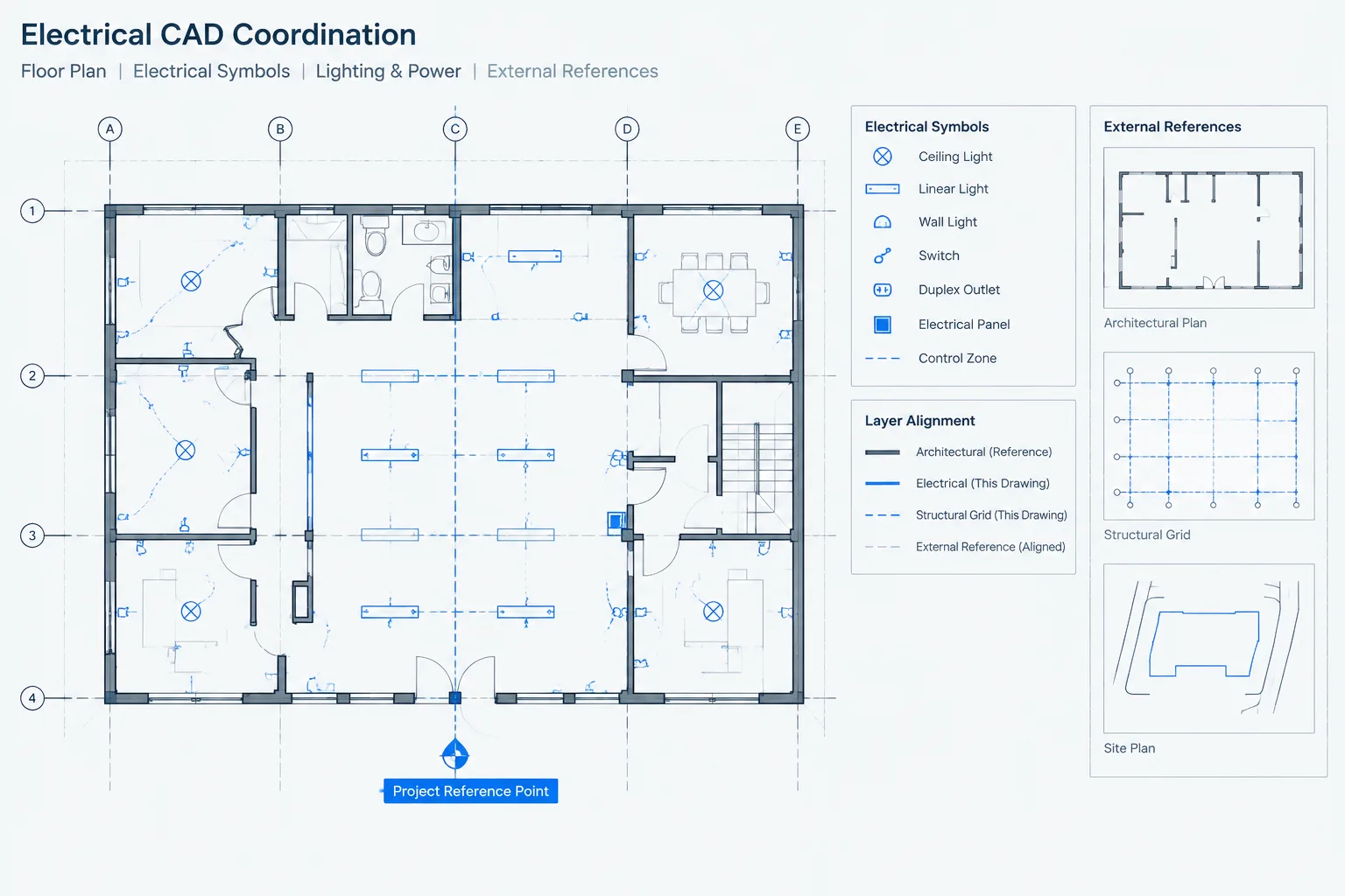
Pathway routing is spatial coordination work. Electrical drawings should be reviewed against current architectural and engineering backgrounds rather than an early base plan that no longer reflects the project.
Pay particular attention to:
- Structural beams, columns, bracing, and slab boundaries
- Mechanical equipment, ductwork, and access areas
- Plumbing and fire protection mains
- Ceiling systems and ceiling-mounted devices
- Doors, hatches, shafts, and service corridors
- Equipment maintenance and replacement paths
- Rated or otherwise controlled construction requiring project-specific detailing
A visually open space on a floor plan may not be available vertically. When several systems share a congested area, create a section rather than adding layers of ambiguous notes to the plan.
Organize CAD Layers for Editing and Output
Layer organization should support visibility control, plotting, and interdisciplinary review. Separate pathway linework from tags, fittings, section references, and background information when doing so improves drawing control.
For example, a project may distinguish tray routes, conduit routes, underground routes, route annotations, and existing pathways. The exact naming convention should follow the project CAD standard. More layers are not automatically better; each layer should serve a clear editing or output purpose.
Keep annotation behavior predictable. Route tags should not disappear when a pathway category is isolated unless that is an intentional part of the layer strategy.
Create a Supporting Pathway Schedule
A pathway schedule can carry information that would make the plan too dense. The fields should reflect the actual project workflow rather than copying a generic template.
| Schedule field | Drawing purpose |
|---|---|
| Route identifier | Connects the schedule entry to plans and diagrams |
| System or service | Clarifies the route classification |
| Origin | Identifies where the documented route begins |
| Destination | Identifies the intended endpoint |
| Pathway description | Records the design description without crowding the plan |
| Drawing reference | Directs readers to relevant plans, risers, sections, or details |
| Remarks | Captures project-specific coordination notes or unresolved items |
Schedules should be checked for orphaned entries, duplicate identifiers, and routes that appear on plans but not in the schedule. If a route is removed, revise both the linework and its associated schedule record.
Distinguish Existing, New, Future, and Removed Work
Renovation drawings need a clear status hierarchy. Existing pathways that remain should not look identical to new work. Removed routes should be recognizable without overwhelming the proposed design, and future provisions should not be mistaken for current scope.
Use the project legend to define the applicable line types and graphic conventions. Status should be communicated by more than color whenever possible because color may not survive every printing and file-sharing workflow.
Perform a Final Routing Drawing Review
Before issuing the drawing, trace each major route from origin to destination as if encountering the plan for the first time. A focused review should confirm that:
- Every route has a clear beginning, endpoint, or continuation.
- Tags agree with schedules, risers, and single-line diagrams.
- Crossings cannot be mistaken for electrical connections.
- Vertical transitions are identified where needed.
- Sections and details are referenced from the correct locations.
- Existing and proposed work are visually distinct.
- Backgrounds are current and unnecessary layers are not obscuring the design.
- Text, symbols, and parallel lines remain readable at the issue scale.
- Unresolved coordination conditions are identified rather than hidden by polished linework.
A clear conduit or cable tray routing plan does not claim that every field condition has been solved. It organizes design intent, highlights important spatial relationships, and gives reviewers a reliable path through the documentation. CAD blocks and pathway symbols support that process, but consistency among plans, diagrams, schedules, and details is what makes the drawing set usable.
What a Routing Plan Should Let a Reviewer Confirm
A reviewer should be able to follow a pathway without guessing whether lines connect, cross, rise, drop, or continue elsewhere. The drawing should also make it possible to compare the route with its origin, destination, system classification, schedule entry, and related diagram.
When that information cannot be communicated clearly in the main plan, use a referenced section, elevation, enlarged view, detail, or schedule. Adding a supporting view is usually more useful than placing several overlapping notes in a congested area.
Document Unresolved Routing Conditions
Polished linework can create a false impression that a route is fully coordinated. If structural depth, ceiling congestion, equipment access, background accuracy, or another spatial condition remains unresolved, identify it through the project review process rather than concealing it behind a precise-looking path.
Maintain a consistent relationship between route graphics and coordination records. When a routing decision changes, review every affected plan, riser, schedule, section, detail, and continuation reference. This prevents an obsolete pathway from remaining in another part of the drawing set.
Review the Drawing in Its Delivered Form
A route that is clear in the working CAD file may become ambiguous after plotting, conversion, or background overlay. Review the intended deliverable with the applicable layer visibility, lineweights, line types, annotation settings, and backgrounds. Confirm that route identifiers remain associated with the correct linework and that crossings, continuations, and status distinctions are still understandable without relying only on color.
Frequently Asked Questions
What is the difference between a routing plan and a single-line diagram?
A single-line diagram explains electrical relationships between equipment and systems. A routing plan shows the intended physical path of conduit, cable tray, or another pathway through a building or site. The documents should use compatible identifiers but serve different purposes.
Should every conduit be drawn separately?
Not necessarily. Individual lines may be useful when separate pathways must be identified or coordinated, while a grouped route with a clear tag may be easier to read in congested areas. The chosen method should match the project documentation approach and remain clear when issued.
How should cable tray be represented on a plan?
Cable tray may be shown with a centerline, an outline, or a simplified symbol. Whichever method is used, it should consistently communicate direction changes, intersections, rises, drops, and references to supporting views. An outline should not imply a fully verified installation envelope unless coordination supports that interpretation.
How can a drawing distinguish a crossing from a connection?
Use an established symbol, annotation, elevation cue, or referenced section. A small gap in linework may disappear or become unclear during plotting and file conversion, so it should not be the only indication when the relationship matters.
What information belongs in a route tag?
A compact tag can identify the pathway, its system or service, and a related schedule or drawing reference. Origin and destination information may also be included when useful. Longer descriptions are often better placed in a schedule.
Why are sections important for pathway routing?
Plan views primarily show horizontal relationships. Sections and elevations clarify vertical stacking, elevation changes, nearby construction, and congested areas that cannot be understood reliably from the floor plan alone.
Should routing plans rely on CAD color?
Color can improve editing and coordination, but essential distinctions should also be communicated through line types, symbols, tags, notes, or other graphic conventions. The drawing must remain understandable in its intended output format.






Leave a Reply
You must be logged in to post a comment.