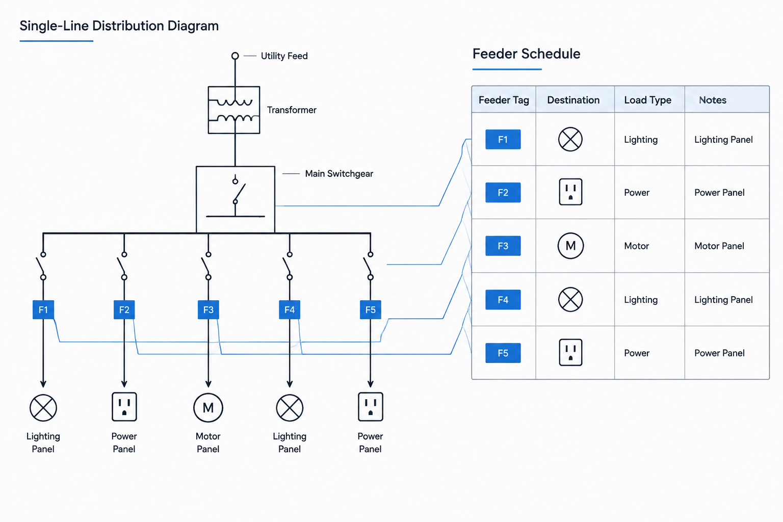
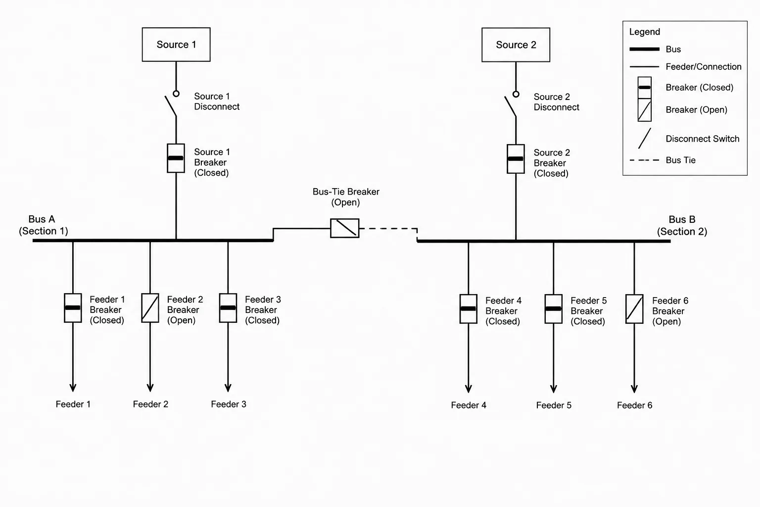
A feeder schedule and a single-line diagram communicate different parts of the same distribution relationship. The diagram shows how equipment is connected, while the schedule organizes the identifiers and descriptive information needed to document each feeder clearly.
This drafting guide explains how to establish stable feeder references, structure schedule fields, coordinate equipment tags, and review changes across an electrical drawing set. It focuses on CAD documentation and quality control; project-specific electrical design information must be established and verified by the responsible professional.
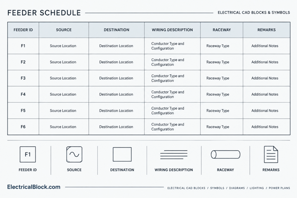
An electrical feeder schedule organizes distribution-circuit information that would otherwise be scattered across single-line diagrams, plans, equipment schedules, and notes. It gives designers and reviewers a structured place to compare feeder origins, destinations, wiring descriptions, raceways, and related remarks.
The schedule is not a substitute for engineering calculations or a complete single-line diagram. Its value is coordination: each feeder can be identified once and then referenced consistently throughout the drawing set. A well-managed schedule also makes revisions easier because the drafting team can trace a feeder across multiple views without relying on visual guesswork.
What an electrical feeder schedule documents
A feeder schedule is usually presented as a table. Each row represents a feeder or another clearly defined distribution connection. The columns describe that connection using the project team’s approved terminology.
Depending on project scope, useful fields may include:
- Unique feeder identification
- Source equipment
- Destination equipment
- System or service description
- Overcurrent device reference
- Phase and conductor description
- Equipment grounding conductor information
- Raceway or cable type
- Parallel-run designation where applicable
- Routing or installation notes
- Drawing or detail references
- Revision status or coordination comments
Not every project needs every field. The table should reflect the information required to understand and coordinate the design, not become a storage location for unrelated specifications.
Feeder schedule versus panel schedule
Although the names sound similar, feeder schedules and panel schedules serve different documentation purposes.
| Drawing element | Primary purpose | Typical organization |
|---|---|---|
| Feeder schedule | Describes distribution connections between sources and downstream equipment | One row per identified feeder |
| Panel schedule | Organizes circuits, loads, and protective-device information associated with a panel | One entry or group of entries per circuit position |
| Single-line diagram | Shows the functional distribution path and major equipment relationships | Connected symbols and lines arranged by system hierarchy |
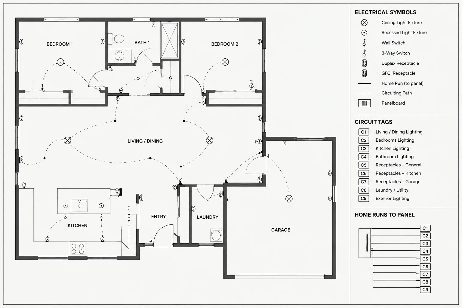
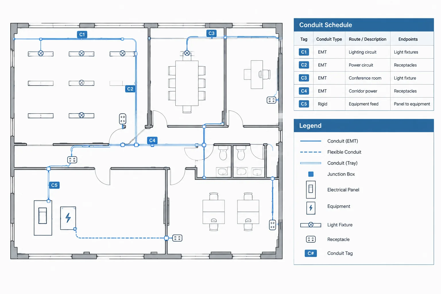
A feeder may appear as a labeled line on the single-line diagram, connect to equipment represented on a floor plan, and terminate at a panel that has its own schedule. The feeder ID provides the common reference among those drawing elements.
Start with a stable feeder identification system
Assigning IDs before building the schedule reduces ambiguity. A useful ID must remain unique even when two feeders have similar destinations or wiring descriptions. It should also be short enough to fit beside single-line graphics without crowding the diagram.
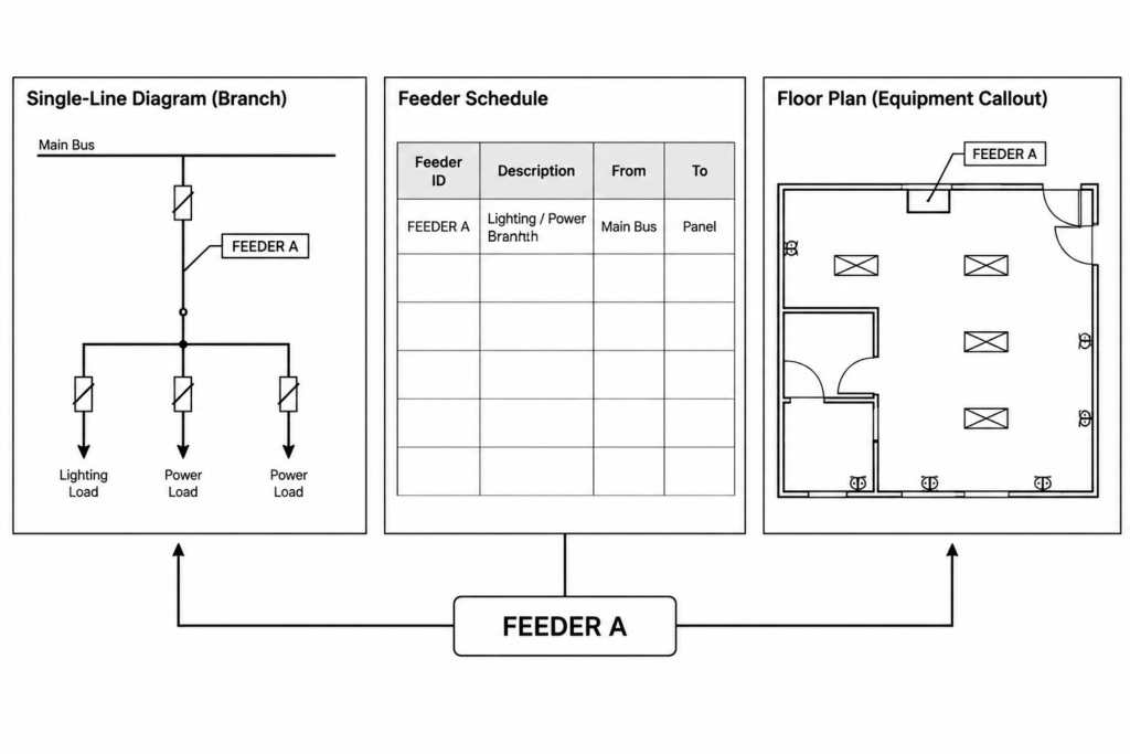
Feeder IDs may follow equipment relationships, system groupings, sequence-based naming, or another office convention. Whichever approach is chosen, apply it consistently. Avoid using a conductor description as the ID because conductor or raceway information may change during design.
The ID should appear in the same form wherever the feeder is referenced:
- Beside the corresponding line on the single-line diagram
- In the feeder schedule row
- At relevant plan callouts or home-run notes
- In details that apply to that specific feeder
- In calculation or coordination records when the project workflow supports cross-referencing
Build the schedule from system relationships
Record the source and destination separately
Source and destination are among the most important columns. Separate fields are clearer than a combined description because they can be checked independently.
Use equipment tags rather than informal location phrases. For example, a source should reference the same switchboard, panel, transformer, generator, or other equipment tag shown on the diagram. The destination should match the receiving equipment tag exactly. If an equipment tag changes, both the diagram and the schedule need coordinated updates.
Separate identification from technical description
Keep the feeder ID in its own column and place wiring information in dedicated fields. This allows a feeder to retain its identity while technical data develops. It also makes sorting, auditing, and schedule extraction more reliable.
Where conductor details are displayed, use a consistent sequence established by the project team. Do not mix several description formats within one table. Abbreviations should be defined in the drawing legend or notes, particularly when they could be interpreted in more than one way.
Use notes for exceptions, not basic data
A remarks column is useful for conditions that do not fit the standard fields, such as a special routing reference or coordination requirement. It should not become the main location for source, destination, or wiring information.
If the same note applies to many feeders, place it in general schedule notes and reference it only where necessary. Repeating long text in multiple rows makes the schedule difficult to scan and increases the chance of inconsistent edits.
Coordinate the schedule with the single-line diagram
The diagram and schedule should be treated as two views of the same distribution model. The diagram explains connectivity; the schedule provides structured detail. Coordination requires more than confirming that the feeder ID appears in both places.
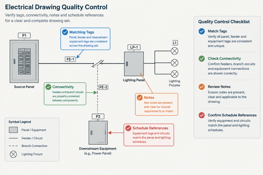
For each scheduled feeder, verify the following relationships:
- The source equipment exists on the single-line diagram.
- The destination equipment exists and is connected to the intended source.
- The feeder ID is unique and readable.
- The system description agrees with the connected equipment.
- Protective-device references do not conflict with the diagram or associated equipment schedule.
- Any parallel or multi-run representation is interpreted consistently.
- Normal, emergency, standby, and other distribution paths are not inadvertently mixed.
- Notes and detail references point to existing drawing content.
Direction also matters. Even if a distribution line is graphically simple, the schedule should make the source-to-load relationship unmistakable. This becomes especially important where transfer equipment, multiple sources, or alternate operating paths are represented.
Drafting the table in CAD
Choose a maintainable table method
A feeder schedule can be created with a native CAD table, linked project data, or carefully controlled linework and text. The best method is the one the project team can revise reliably. A visually polished table is not useful if editing it breaks alignment or creates duplicate information.
Native table objects can help preserve row and column structure. Data-linked workflows may reduce repetitive entry, but they require clear ownership and update procedures. If ordinary text and lines are used, establish fixed text styles, alignment rules, and row spacing so revisions remain orderly.
Control column widths by content
Do not give every column equal width. IDs and compact references generally need less room than conductor descriptions or remarks. Column headings may be wrapped if doing so produces a more readable table.
Test the schedule at its intended plotted presentation, not only at a comfortable on-screen zoom level. Confirm that headers, grid lines, row text, and note references remain distinguishable from one another.
Keep schedule graphics on controlled layers
Place schedule text, borders, headers, and related references on layers that follow the project’s CAD standards. Separating these elements can make plotting and global revisions easier. However, excessive layer subdivision may complicate editing, so use only distinctions that support the actual workflow.
Managing revisions without losing coordination
Feeder changes often affect several drawings. Changing only the schedule can leave the single-line diagram, equipment plan, or associated schedule out of date. A revision workflow should therefore begin with a feeder-centered impact check.
When a feeder is added, removed, or modified:
- Locate every appearance of its ID.
- Check the source and destination equipment tags.
- Review the single-line connection.
- Review associated plan callouts and equipment schedules.
- Confirm whether notes, details, or calculations require updates.
- Remove obsolete references rather than leaving them hidden or crossed out in working files.
- Record the change according to the project’s revision procedure.
If schedule data comes from an external source, identify whether CAD or the external file is authoritative. Uncontrolled editing in both locations can cause one version to overwrite correct changes from the other.
Common drafting problems
Duplicate feeder IDs
Duplicate IDs make cross-references unreliable. Search the complete drawing set or source data before assigning a new identifier, especially when copying diagram branches or schedule rows.
Equipment tags that do not match
Small differences in punctuation, spacing, or abbreviations can make one piece of equipment appear to be several different items. Use the project’s approved tag format and avoid manually retyping tags when a controlled data workflow is available.
Too much information beside diagram lines
Placing complete feeder descriptions directly on a single-line diagram can crowd equipment symbols and obscure connectivity. A compact feeder ID linked to a schedule often produces a clearer diagram, while selected essential information may remain on the line where the project convention requires it.
Unexplained abbreviations
Abbreviations save space only when readers can interpret them. Define project-specific shorthand and avoid using the same abbreviation for different concepts.
Rows that no longer connect to anything
Copied or abandoned rows can survive long after a diagram revision. Every issued schedule row should correspond to an intentional distribution connection or be clearly identified for its documented purpose.
Final feeder schedule quality-control checklist
- Every feeder ID is unique.
- Each row has an identifiable source and destination.
- Equipment tags match the plans, diagrams, and schedules.
- Feeder descriptions follow one consistent format.
- Abbreviations are defined.
- Schedule notes are concise and correctly referenced.
- No unexplained blank fields remain.
- Diagram connectivity agrees with the tabulated relationship.
- Text and grid lines are readable at the intended plotted presentation.
- Obsolete rows and references have been removed.
- Technical values have been checked by the responsible project professional.
A coordinated schedule is a navigation tool
The strongest electrical feeder schedule does more than compress technical information into rows and columns. It helps readers move confidently between the distribution diagram, equipment plans, panel information, and supporting details.
CAD blocks and schedule templates can improve consistency, but they do not validate design data. Feeder sizes, protective-device information, system arrangements, and installation descriptions must be developed and verified for the specific project. When stable IDs, structured fields, and disciplined revision checks are used together, the feeder schedule becomes a practical coordination tool rather than another isolated table.
Use a trace test before issuing the drawings
A practical coordination review is to select a feeder schedule row and trace it through every relevant drawing view. Begin with the feeder ID, locate its source and destination on the single-line diagram, and then check related plan callouts, equipment schedules, details, and notes. Repeat the process in reverse by starting with a diagram connection and confirming that the corresponding schedule entry can be found without interpretation or guesswork.
This trace test evaluates more than spelling. It can reveal disconnected schedule rows, duplicated identifiers, outdated equipment tags, unclear source-to-destination relationships, and references that point to removed details.
Distinguish blanks from intentional omissions
An empty schedule cell can mean that information is pending, not applicable, intentionally shown elsewhere, or accidentally omitted. Those meanings should not be left to the reader. Apply the project team’s approved notation and review method so incomplete information can be distinguished from a deliberate omission.
Assign ownership for coordinated data
When schedule information is maintained in more than one file or application, the team should identify the authoritative source and the person or discipline responsible for updates. Clear ownership helps prevent a corrected feeder description from being replaced by older data during a later import or drawing update.
Preserve readability when the schedule grows
As distribution documentation expands, avoid solving every space problem by reducing text size or compressing columns. Consider logical grouping, repeated headings, controlled continuation formatting, or separation by system when those methods fit the project documentation standard. Readers should be able to follow the schedule without losing the meaning of its headers or feeder groups.
Why coordinated feeder data improves drawing review
Consistent identifiers let reviewers compare connectivity and tabulated information without repeatedly decoding long wiring descriptions. They also give revision teams a searchable reference that can be followed across CAD files and supporting records. The result is not a substitute for engineering review, but it is a stronger documentation framework for finding conflicts before drawings are issued.
Feeder schedule coordination FAQ
Should every line on a single-line diagram have a feeder schedule row?
Not necessarily. The schedule scope depends on the project’s documentation method. Each scheduled row should correspond to an intentional connection, and every connection intended to be scheduled should have a clear reference. General diagram lines that represent other relationships may be documented differently.
Can the feeder description be used as the feeder ID?
A stable identifier is generally more useful because descriptive information may change as the design develops. Keeping the ID separate allows the connection to retain its reference while conductor, raceway, routing, or protective-device information is revised.
What should happen when an equipment tag changes?
Search for the previous tag throughout the drawing set and any controlled source data. Update the feeder schedule, single-line diagram, plans, equipment schedules, details, and applicable notes together, then verify that no obsolete references remain.
How should alternate source paths be documented?
The graphics and schedule fields should make the source-to-destination relationship understandable without relying on line position alone. Transfer equipment and alternate operating paths require especially careful use of identifiers, equipment tags, and explanatory notes. The responsible project professional must verify the actual system arrangement.
Is a CAD table better than text and linework?
Neither method is automatically correct for every workflow. A native table can support structured editing, while controlled text and linework may match an established office process. The preferred method is the one that preserves alignment, supports reliable revisions, and avoids conflicting copies of the same data.
Who verifies feeder technical information?
CAD staff can check consistency, legibility, references, and coordination between drawings. Technical design values and system relationships must be reviewed by the responsible project professional rather than assumed from a template or copied schedule.


Leave a Reply
You must be logged in to post a comment.