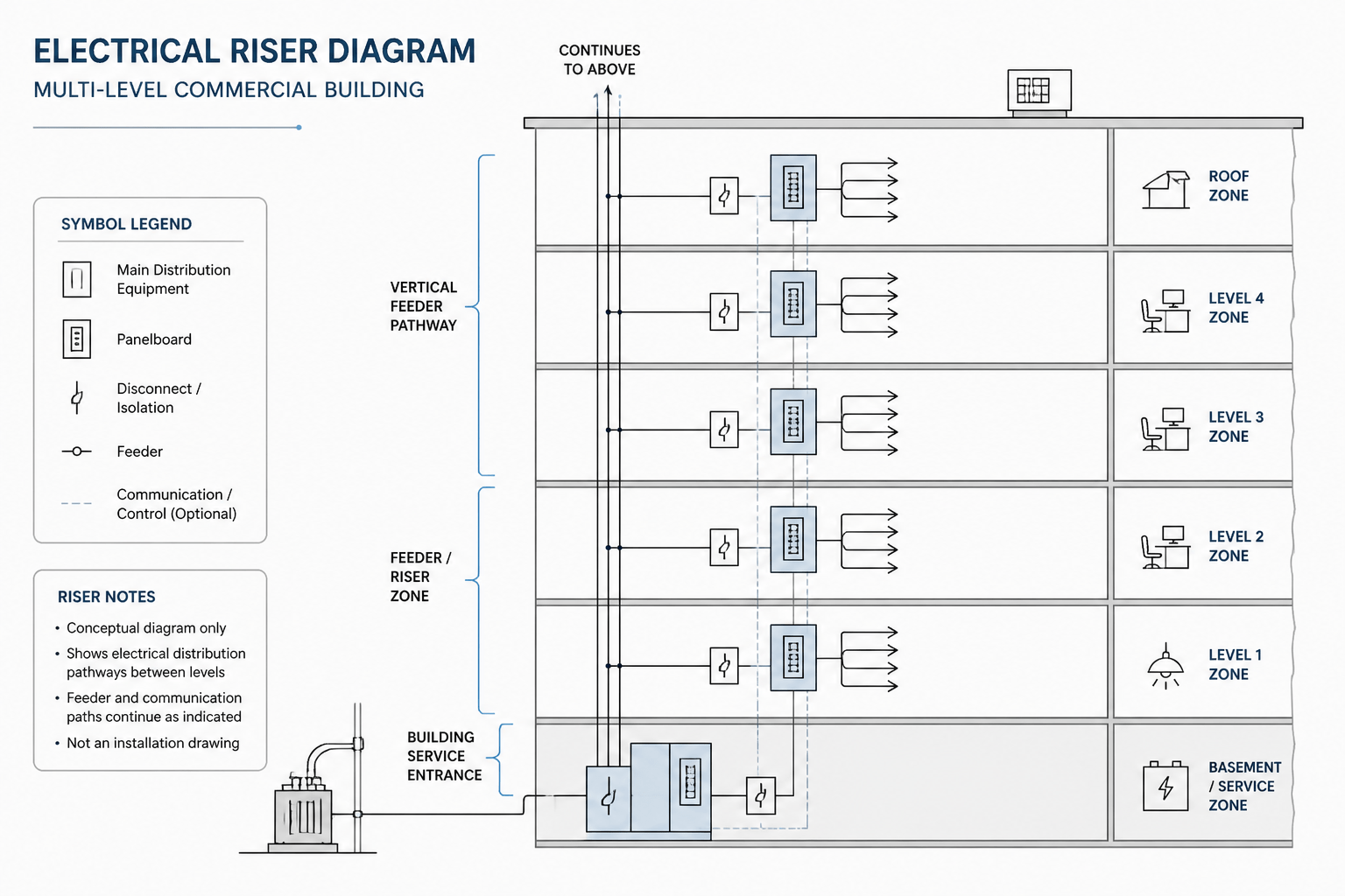
Reading an electrical riser diagram is primarily an exercise in following relationships. The reader traces sources, distribution equipment, floor connections, and vertical pathways while using tags and references to locate supporting information elsewhere in the drawing set.
This guide explains how to interpret those relationships and coordinate them with electrical CAD plans, schedules, legends, and equipment lists. It focuses on drawing review and documentation rather than installation or field procedures.
An electrical riser diagram is a schematic view of how electrical systems move vertically through a building. Instead of showing every device in its exact plan location, it emphasizes relationships between floors, distribution equipment, feeders, junction points, and vertical pathways. This makes the riser diagram useful for understanding the building-wide structure of an electrical system before reviewing detailed floor plans.
For CAD users, the riser is also a coordination document. It can reveal whether a panel shown on one floor connects to equipment above or below, whether a vertical pathway has been represented consistently, and whether drawing labels agree across plans, schedules, and diagrams. The diagram is conceptual and must not be treated as a complete or installation-ready electrical design.
What an electrical riser diagram shows
A typical electrical riser diagram organizes the distribution system along a vertical path. The drawing may represent several building levels as horizontal bands or stacked zones, with electrical equipment and connections arranged between them. Depending on the project, it can cover normal power, emergency power, lighting distribution, communications pathways, or other systems in separate diagrams.
Common diagram elements include:
- Incoming source: The point where electrical service or another upstream source enters the documented system.
- Main distribution equipment: Equipment that receives power and routes it to downstream portions of the building.
- Panelboards and distribution boards: Labeled destinations that serve areas or systems on specific floors.
- Vertical feeders or pathways: Lines representing electrical connections, riser spaces, busways, conduit groups, cable routes, or other containment concepts.
- Floor-level connections: Branch points showing where a floor or zone connects to the vertical distribution.
- Grounding and bonding references: Conceptual connections to the building grounding and bonding arrangement, when included in the drawing set.
- Notes and identifiers: Tags that connect the riser to plans, schedules, equipment lists, and details.
The graphic style varies between offices and projects. Some diagrams use simplified electrical symbols, while others rely mainly on equipment rectangles, line types, arrows, and text labels. The legend and project-specific conventions should always be read before interpreting an unfamiliar diagram.
Electrical riser diagram versus single-line diagram
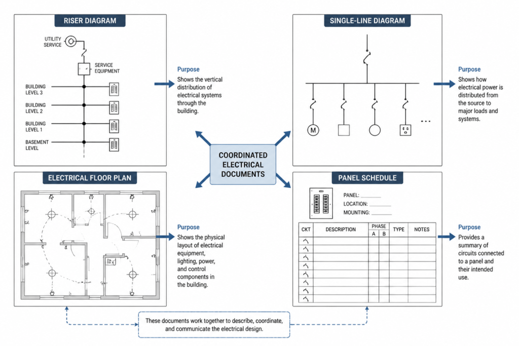
An electrical riser diagram and a single-line diagram can overlap, but they answer different drawing questions.
| Document | Primary purpose | Typical emphasis |
|---|---|---|
| Electrical riser diagram | Show vertical distribution relationships through a building | Floors, riser pathways, panels, shafts, and level-to-level connections |
| Single-line diagram | Describe the logical flow of an electrical distribution system | Sources, distribution equipment, switching, protection concepts, and downstream connections |
| Electrical floor plan | Show equipment and devices in a horizontal building view | Rooms, device locations, routing, and coordination with architectural backgrounds |
| Panel schedule | Organize circuits associated with a panel | Circuit identifiers, descriptions, connected loads, and other project data |
A riser may use single-line conventions, and a single-line diagram may include vertical distribution information. The distinction is therefore based on the document’s purpose rather than its appearance alone. When documents disagree, the discrepancy should be recorded for project review rather than resolved by guessing.
How to read an electrical riser diagram
Start with the drawing title, legend, and notes
First identify the system represented, the drawing scope, and the symbol convention. A power riser, lighting riser, emergency distribution riser, and communications riser may use similar graphic structures but represent different relationships. Review abbreviations, line-type meanings, arrow conventions, and equipment tag formats before tracing any connection.
Also check whether the diagram is schematic, not-to-scale, or intended only as a system overview. A line that appears short or long usually does not represent a physical route length. Similarly, the location of a symbol on the page may show sequence or connectivity rather than its exact position in the building.
Trace the system from the source downward or upward
Choose a clear starting point, such as the documented incoming source or the main distribution equipment. Follow each downstream connection and note where it branches. Read equipment tags exactly as shown. A panel identifier, feeder label, or pathway reference should be matched to the same identifier on the floor plan, panel schedule, or equipment schedule.
When tracing a line, distinguish between a physical connection, a continuation reference, and a graphic crossing. Arrows may indicate direction or continuation, while a junction dot may indicate a connection. These conventions are not universal, so the project legend takes priority.
Read the building levels as coordination zones
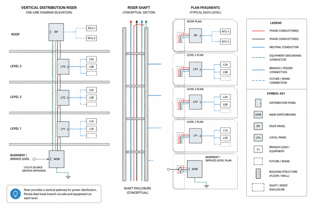
Many risers divide the drawing into basement, ground, intermediate, or roof-level zones. Treat each zone as a coordination checkpoint. Ask:
- Which electrical equipment is assigned to this level?
- Which equipment is supplied from another level?
- Where does the vertical pathway enter or leave the floor?
- Does the plan show the same equipment tag and room relationship?
- Are continuation references used at shaft, riser, or service-room boundaries?
This approach helps separate two related but different questions: how the system is connected and where the equipment is physically located.
Coordinating the riser with electrical CAD plans
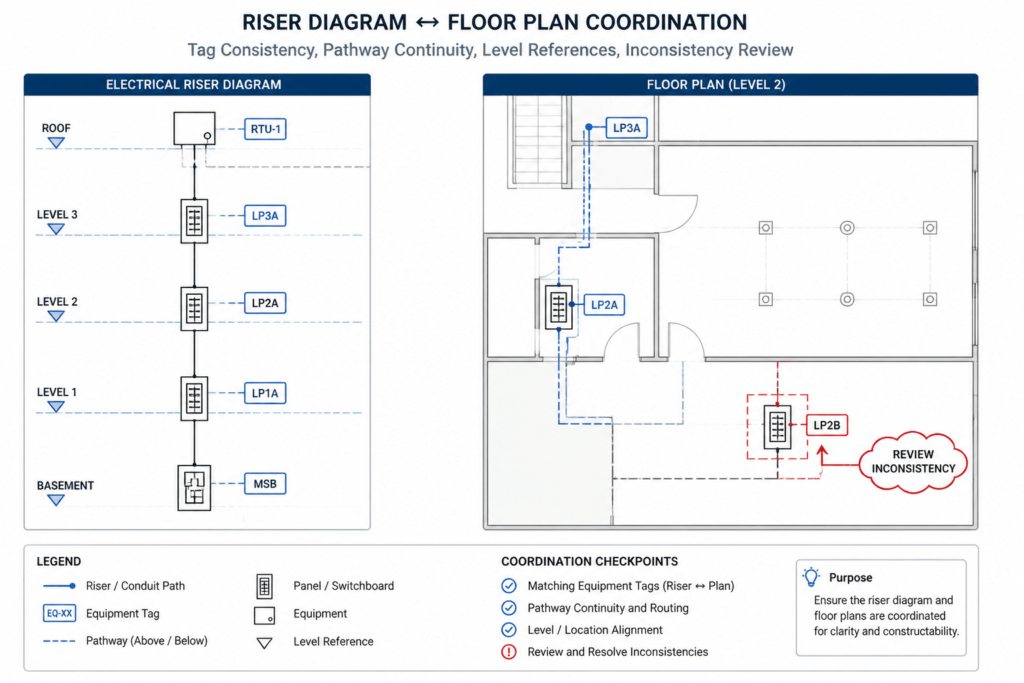
Coordination is more reliable when the riser is treated as a reference map rather than as an isolated diagram. Open the riser and the related floor plans together, then compare identifiers systematically.
Compare equipment tags
Panel, switchboard, transformer, transfer equipment, junction box, and other tags should be consistent wherever they appear. A mismatch may result from a simple drafting error, a design change, or different drawing scopes. Do not silently rename the equipment in one view. Mark the issue and confirm the intended reference through the project documentation process.
Compare pathway continuity
A vertical line on the riser should have a corresponding conceptual pathway or shaft relationship on the plans when that information is within the plan’s scope. The plan may show conduit, cable tray, busway, sleeves, or a designated riser space using different symbols and layers. The riser does not replace the detailed routing information on the plan.
Compare floor connections
Check that floor-level branches shown on the riser have corresponding distribution points on the plans. A branch may serve a panel, mechanical equipment area, lighting zone, or another documented system. The exact circuiting and device arrangement normally require additional documents, so the riser should not be used to infer details that are not drawn.
Compare schedules and equipment lists
Use schedules to verify naming and documented relationships. A panel shown on the riser may be listed in a panel schedule, while larger distribution equipment may appear in an equipment schedule or diagram. Look for inconsistent descriptions, missing references, or tags that appear in one document but not another.
CAD organization for riser diagrams
Riser drawings benefit from clear separation between system graphics, annotation, building references, and coordination information. Useful layer groups may include:
- Equipment graphics: Boxes or symbols representing panels and distribution equipment.
- Connection graphics: Lines, arrows, riser pathways, and continuation indicators.
- Level references: Floor labels, shaft references, and building-zone markers.
- Text and tags: Equipment identifiers, feeder references, notes, and abbreviations.
- Background references: Simplified architectural or structural information used for orientation.
- Review information: Revision clouds, coordination markers, and issue notes kept separate from the final system graphics.
Blocks can improve consistency for repeated equipment symbols, but a block should not hide important attributes or create ambiguous connections. Keep attributes editable and use a consistent insertion orientation. Before issuing a drawing, inspect the riser at the intended plotting scale to confirm that line weights, tags, and level labels remain legible.
Common reading and drafting mistakes
- Assuming the diagram is to scale: Schematic spacing usually communicates sequence, not physical distance.
- Ignoring the legend: Similar line styles can represent different relationships on different projects.
- Confusing a pathway with a circuit: A riser space or containment route is not automatically a complete circuit description.
- Using a floor plan to fill undocumented gaps: A plan may omit information that is intentionally shown only in a diagram or schedule.
- Overlooking continuation references: A line that ends at a drawing boundary may continue elsewhere.
- Duplicating outdated equipment tags: Copying blocks between floors can preserve obsolete labels or attributes.
Using an electrical riser diagram as a reference
For drawing readers, the riser provides a fast overview of vertical distribution and helps establish where to look next in the document set. For CAD technicians, it provides a useful coordination check between schematic relationships and plan-based locations. For reviewers, it highlights missing references, inconsistent tags, unexplained branches, and unclear system boundaries.
The most effective workflow is to read the riser with the legend, floor plans, schedules, and relevant details as a coordinated group. Treat every symbol and label as project-specific unless the drawing clearly establishes a convention. A clean riser diagram does not replace engineering review, field verification, or the complete set of project documents; it makes those reviews easier by presenting the system’s vertical relationships in one organized view.
A practical riser coordination workflow
A structured review helps prevent assumptions from being carried between drawings. Begin with the diagram legend and system scope, trace the documented distribution path, and record each equipment tag or continuation reference that must be confirmed on another sheet.
- Establish the document context: Confirm which electrical system and building areas the riser represents.
- Follow connectivity: Trace lines through equipment, branches, floor zones, and continuation points without interpreting schematic spacing as physical distance.
- Match identifiers: Compare equipment tags, panel names, pathway references, and schedule entries exactly as documented.
- Separate location from relationship: Use the riser to understand system connections and the floor plans to understand plan-based placement and routing.
- Log discrepancies: Record missing, duplicated, or conflicting information for formal project review instead of resolving it through drafting assumptions.
Revision control during CAD coordination
Riser coordination should include a check of drawing revisions and referenced files. A correctly labeled block can still be unreliable if it came from an outdated plan, schedule, or external reference. Review clouds, issue notes, and file dates within the project documentation system can help identify where a change originated.
When equipment is renamed or relocated, review every connected document rather than updating only the visible symbol. The same identifier may appear in the riser, floor plan, panel schedule, equipment list, detail reference, and annotation. Keeping review markup separate from final drawing graphics also makes unresolved coordination items easier to track.
Questions to ask before completing the review
- Does every major equipment tag lead to a corresponding plan or schedule reference?
- Can each vertical pathway be followed through the applicable floor zones?
- Are line crossings, junctions, arrows, and continuation markers interpreted according to the project legend?
- Do the plans and riser describe the same upstream and downstream relationships?
- Are unexplained branches, missing destinations, and conflicting labels clearly marked for review?
A coordinated drawing set does not require every document to repeat the same information. It requires the documents to use compatible identifiers, references, and system relationships so the reader can move between them without guessing.
Electrical riser diagram FAQ
Is an electrical riser diagram drawn to scale?
It is generally read as a schematic representation of connectivity and vertical organization. The project notes should confirm the drawing convention, while floor plans and details provide the relevant location and routing context.
Why can equipment appear in a different position on the riser and floor plan?
The riser arranges equipment to clarify system relationships. A floor plan places equipment within rooms and building geometry. Symbol position on the riser should not be treated as an exact plan location.
What should be checked when a tag appears on the riser but not on the plan?
Review the drawing scope, schedules, equipment lists, continuation references, and current revisions. If the destination remains unclear, record the discrepancy for project review rather than creating a location or connection.
Does a vertical riser line always represent conduit?
No. Depending on the legend and drawing scope, it may represent a feeder, busway, cable route, containment path, shaft relationship, or another conceptual connection. The line meaning must come from the project documentation.
Can a riser diagram replace a single-line diagram?
Not automatically. The documents may share symbols and distribution information, but each is organized around a different purpose. The riser emphasizes building levels and vertical relationships, while the single-line diagram emphasizes logical system flow.
How should CAD users handle conflicting information?
Keep the original references visible, mark the conflict, and follow the established documentation review process. Silently changing a tag or connection can hide a coordination issue and create further inconsistencies.












Leave a Reply
You must be logged in to post a comment.