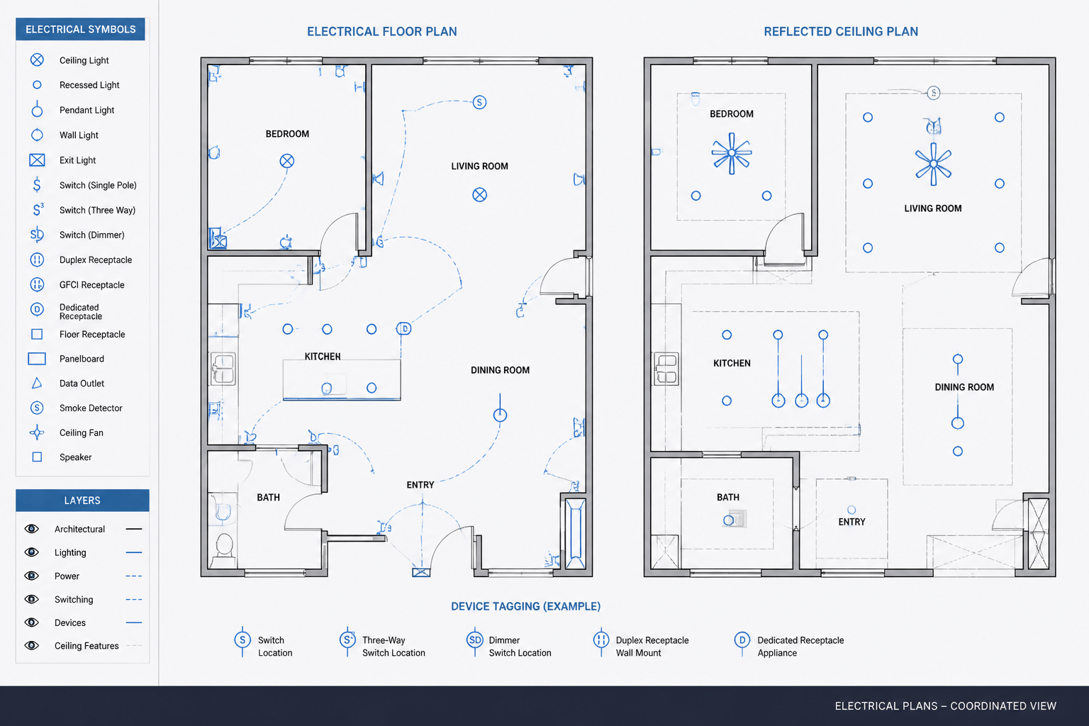
Coordinating an electrical floor plan with a reflected ceiling plan is both a drafting task and an information-management task. The objective is not to make the views identical, but to ensure that device locations, control relationships, architectural backgrounds, and drawing references communicate one consistent design intent.
This guide explains how to coordinate the views in CAD, assign information to the appropriate plan, manage external references and layers, and review related sheets without creating unnecessary duplication.
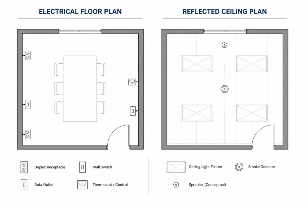
Electrical drawings rarely communicate an entire design on one plan. A floor plan may show receptacles, switches, equipment connections, and general device locations, while a reflected ceiling plan (RCP) shows ceiling-mounted luminaires, sensors, speakers, and other overhead elements. These views are related, but they are not interchangeable.
Good coordination means that the information on each drawing supports the others without creating contradictory locations or unclear design intent. In a CAD workflow, this requires more than copying symbols between sheets. The drafter or reviewer must understand which view controls each type of information, how devices relate to architectural elements, and where circuit or switching information is documented.
What each electrical plan is intended to show
Electrical floor plan
An electrical floor plan uses the architectural floor plan as its background and focuses on devices located at walls, floors, furniture zones, or equipment areas. Depending on the project, it may include:
- Receptacles and specialty outlets
- Wall switches and control stations
- Equipment connection points
- Power-related devices associated with mechanical or architectural equipment
- General notes, circuit references, and equipment identifiers
- Home-run or circuiting graphics when that information is part of the drawing set
The floor plan helps the reader understand how electrical devices relate to rooms, partitions, doors, casework, workstations, and equipment footprints. It is usually the more useful view for reviewing wall-mounted devices and power distribution relationships at the room level.
Reflected ceiling plan
An RCP represents the ceiling as if it were reflected onto the floor plane. It is used to coordinate items that are mounted in, on, or below the ceiling, such as:
- Light fixtures and lighting layouts
- Ceiling-mounted occupancy or environmental sensors
- Exit or emergency-related visual devices when shown at the ceiling
- Ceiling speakers, wireless access points, and similar low-voltage devices
- Ceiling grids, soffits, bulkheads, and other architectural features that affect device placement
The RCP is not simply a duplicate of the floor plan with lighting symbols added. Its orientation and background information are selected to make overhead coordination easier. For example, a wall shown on an RCP may be represented differently from a wall on a typical floor plan, so the reader should use the view title, orientation, and notes rather than assuming every graphic has the same meaning.
Why coordination between the views matters
A ceiling fixture can appear correctly placed on an RCP while its switch is missing from the corresponding floor plan. A wall-mounted device may be shown on the floor plan in a location occupied by a ceiling feature, soffit, or access panel shown on the RCP. These are coordination problems even when each individual sheet looks organized.
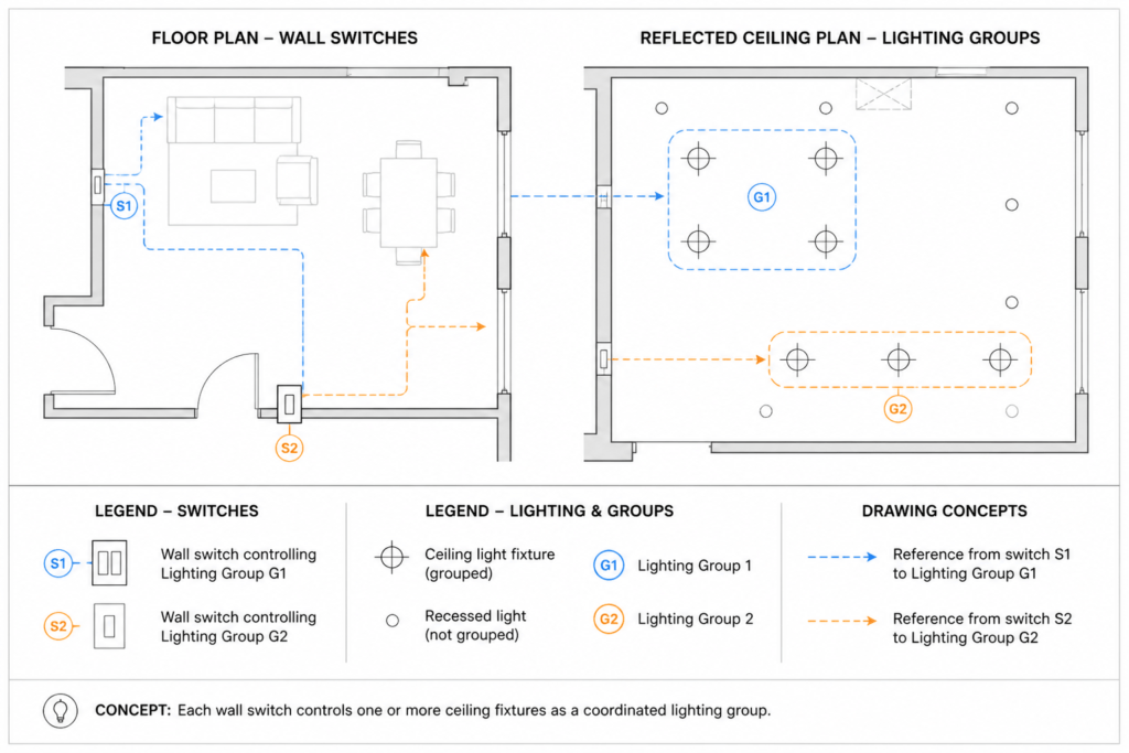
Coordination also helps prevent ambiguous references. A lighting control symbol may be connected graphically to a fixture group, identified by a control tag, or explained through a schedule or note. If the floor plan and RCP use different tags or inconsistent graphic conventions, a reader may not know which fixtures are controlled together.
Establish a clear division of information
Before drafting, decide which sheet is the primary location reference for each device category. The exact division depends on the project and drawing standards, but a practical approach is:
| Information type | Typical primary view | Coordination consideration |
|---|---|---|
| Wall receptacles | Electrical floor plan | Check walls, casework, equipment, and furniture relationships. |
| Ceiling-mounted luminaires | Reflected ceiling plan | Check ceiling geometry, room use, and architectural features. |
| Wall switches | Electrical floor plan | Relate switch locations to doors, room entries, and control intent. |
| Lighting control groups | RCP with control references | Use matching tags, notes, or circuit references across the set. |
| Equipment connections | Floor plan or equipment plan | Coordinate with equipment schedules and the relevant diagram. |
| Ceiling low-voltage devices | RCP or dedicated technology plan | Check separation, access, coverage intent, and discipline ownership. |
This table is a drafting framework, not a universal drawing requirement. Project-specific instructions, consultant responsibilities, and sheet organization should control the final arrangement.
Use symbols and tags consistently
Symbol consistency is one of the simplest ways to make related drawings easier to read. A luminaire symbol should retain the same identity when it is referenced in a lighting schedule, control diagram, or electrical plan. If a symbol is too small or visually dense at the intended plotting scale, use a clear tag or keyed note rather than adding more graphic detail.
Switching relationships deserve particular attention. A switch symbol on the floor plan may be associated with one or more fixtures on the RCP through a control tag, dashed control line, keynote, or other project convention. Do not assume that a physical line between a switch and a fixture always represents wiring. The legend and general notes should define the meaning of each graphic method.
Likewise, avoid using a generic symbol when the drawing needs to distinguish between different device functions. A ceiling device may be a luminaire, sensor, speaker, camera, or access point. Their symbols should be recognizable and supported by the legend, while overlapping devices should be offset or tagged in a controlled manner.
Coordinate CAD layers and external references
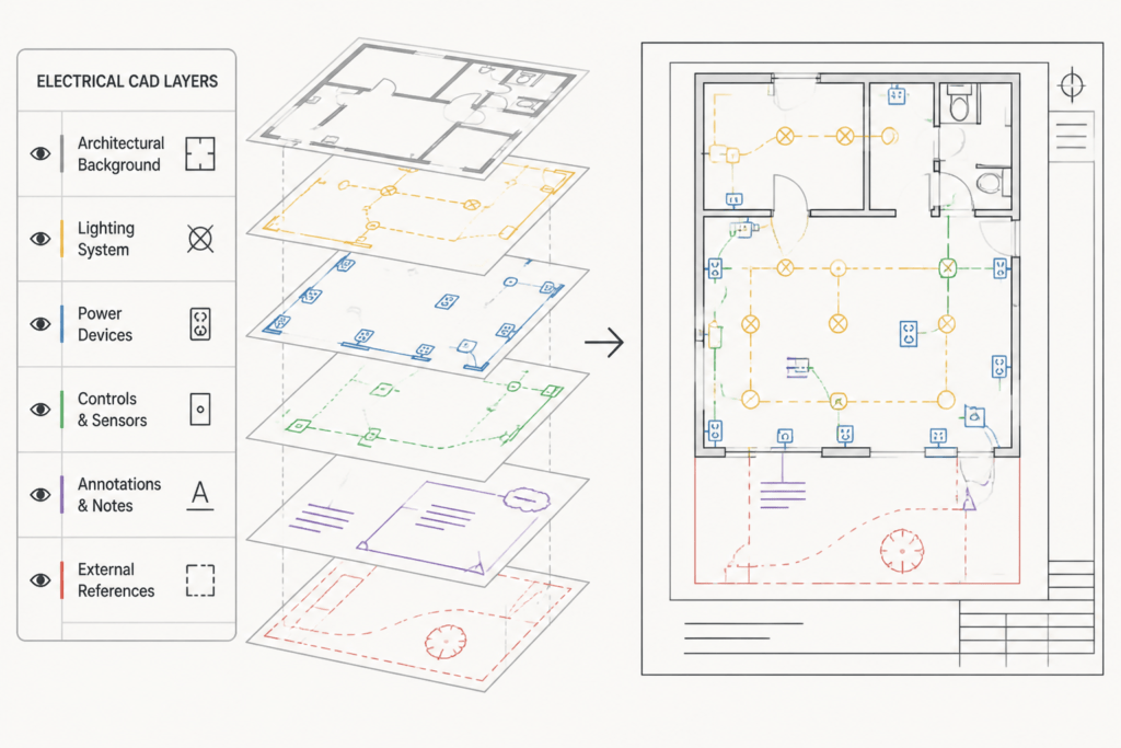
CAD layer organization should help users isolate information without hiding relationships. Common layer groups may separate architectural backgrounds, lighting, power devices, controls, low-voltage devices, annotation, circuiting, and sheet-specific notes. The exact layer names are less important than consistent use, clear plotting behavior, and documented responsibilities.
When an architectural plan or RCP is attached as an external reference, verify its insertion point, orientation, scale behavior, and visibility settings. A background that is slightly misaligned can make device coordination appear correct in one area and incorrect in another. Lock reference layers where appropriate, and avoid editing the source background from the electrical drawing unless the workflow explicitly allows it.
Use separate annotation for electrical symbols rather than modifying the architectural reference to improve visibility. This keeps the drawing easier to update when the architectural background changes and makes it clearer which discipline owns each graphic.
A practical coordination workflow
- Confirm the drawing backgrounds. Check that the floor plan and RCP represent the same area, orientation, room naming, and revision context.
- Review architectural constraints. Identify partitions, doors, ceiling transitions, bulkheads, equipment zones, furniture, and other features that affect device placement.
- Place primary devices in the appropriate view. Start with the view that best represents the physical mounting condition.
- Add related control and identification information. Match fixture tags, switch references, equipment identifiers, and notes across sheets.
- Compare overlapping locations. Look for conflicts between ceiling devices, wall devices, access panels, diffusers, structural elements, and architectural features.
- Check connectivity or intent graphics. Confirm that circuit lines, control lines, homeruns, or references use the project convention and do not obscure the plan.
- Review at plotted scale. A drawing can look clear while zoomed in but become unreadable when printed or exported. Check symbol density, tags, line weights, and masking.
- Record unresolved items. Use a coordination note or review mark rather than silently moving a device when the background information is uncertain.
Common CAD mistakes to avoid
- Duplicating devices without a purpose: Repeating the same fixture or outlet on multiple sheets can create uncertainty about which location is authoritative.
- Using an RCP as a substitute for a power plan: Ceiling graphics do not replace wall-device, equipment, or circuit information that belongs on another view.
- Breaking symbol relationships during edits: Exploding blocks or changing tags manually can cause inconsistent graphics across similar rooms.
- Ignoring ceiling height changes: Soffits, suspended elements, and ceiling transitions can affect whether a symbol belongs in a particular ceiling zone.
- Overloading the plan with circuiting: Excessive lines can hide rooms and symbols. Use references, schedules, or a diagram when they communicate the intent more clearly.
- Failing to update both views: Moving a switch, fixture, or equipment connection on one sheet should trigger a review of every related plan, schedule, and diagram.
How to use reference drawings and CAD blocks responsibly
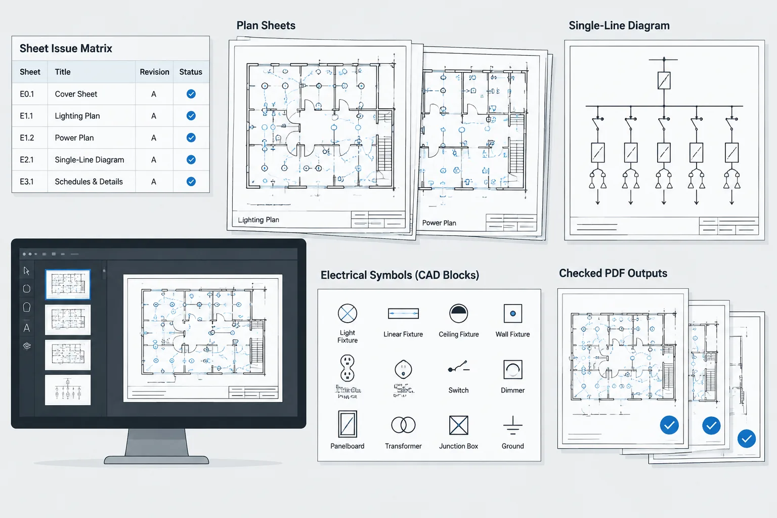
Reference symbols and CAD blocks can accelerate drafting, but they should be treated as graphic resources rather than proof of design suitability. Before placing a block, inspect its insertion units, orientation, layer assignments, linework, attributes, and plotting behavior. Remove unnecessary nested detail and adapt the block to the project legend and drawing scale.
A downloaded or inherited symbol may also use terminology that differs from the current project. Compare it with the project legend and revise the label or graphic representation when necessary. The goal is a consistent, understandable drawing—not the preservation of an unfamiliar block exactly as received.
Final review questions
Before issuing coordinated electrical plans, ask:
- Can a reader identify which view controls each device location?
- Do room names, walls, doors, and major architectural features align?
- Are lighting fixtures, switches, and control references coordinated?
- Are symbols, tags, layers, and line types explained by the legend or notes?
- Do equipment and specialty devices appear in the view where their relationships are easiest to understand?
- Does the plotted drawing remain legible without relying on excessive zooming?
When the floor plan and reflected ceiling plan are treated as connected parts of one documentation system, they provide a clearer record of device locations, control intent, and architectural coordination. The result is easier for designers, reviewers, installers, and future CAD editors to interpret—without forcing one sheet to carry information that belongs elsewhere.
Strengthening coordination through change management
Coordination should continue after the initial device layout is complete. Architectural revisions, equipment changes, ceiling modifications, and updated room uses can affect several electrical documents at once. A reliable CAD workflow treats each revision as a reason to review connected plans, schedules, diagrams, legends, and notes.
Use a coordination overlay
A temporary overlay can reveal differences that are difficult to notice while reviewing separate sheets. Display the floor-plan background, ceiling background, electrical devices, and control information together using distinguishable layer states or visual properties. Compare room boundaries, doors, ceiling transitions, equipment zones, and device locations before returning to the normal plotting configuration.
The overlay is a review tool rather than an additional issued plan unless the project documentation specifically calls for one. Its purpose is to expose conflicts without changing which drawing controls the final information.
Track drawing dependencies
When a device changes, identify every document that depends on it. Moving a luminaire may affect its control association, tag position, circuit reference, schedule entry, or nearby ceiling devices. Moving a switch may affect the floor plan, control graphics, room notes, and references on the RCP.
- Location dependency: The device must remain coordinated with the current architectural background.
- Identification dependency: Tags and equipment identifiers must agree wherever they appear.
- Control dependency: Switching or control references must continue to point to the intended device group.
- Documentation dependency: Legends, schedules, diagrams, and notes must use compatible terminology.
Separate unresolved coordination from approved changes
Uncertain conditions should remain visible in the review process. Use the project’s established markup, issue, or coordination-note method instead of moving a device based on an assumption. This preserves design responsibility and helps the team distinguish a confirmed revision from a proposed solution.
Perform a sheet-set review
A final review should compare the related drawings as a set rather than checking each sheet in isolation. Confirm that the views use compatible backgrounds, room names, device identifiers, legends, and revision information. Then review the plotted or exported output to verify that overlapping symbols, masks, line types, and annotation remain readable.
Frequently asked questions
Which drawing should control an electrical device location?
The primary view should be the one that best represents the device’s mounting condition and coordination context. Wall and floor devices are commonly located on the electrical floor plan, while ceiling-mounted devices are commonly located on the RCP. Project-specific drawing conventions and discipline responsibilities take precedence.
Should a ceiling fixture also appear on the electrical floor plan?
Only when its appearance serves a defined documentation purpose. Unmanaged duplication can create conflicting locations or tags. If the fixture must be referenced from another plan, a tag, note, or other established cross-reference may communicate the relationship more clearly than a duplicate symbol.
How can CAD users identify a misaligned floor plan and RCP?
Compare stable architectural features such as room boundaries, doors, columns, and major equipment areas. A temporary overlay of the current external references can help reveal differences in insertion, orientation, or revision status.
Does a line between a switch and a fixture represent electrical wiring?
Not necessarily. It may represent control intent, grouping, or another project-specific relationship. The drawing legend and notes should define the line type rather than leaving its meaning to assumption.
What should be reviewed after an architectural background changes?
Reload and verify the affected references, then review device locations, control associations, tags, circuit graphics, schedules, and related diagrams. Pay particular attention to changed partitions, doors, ceilings, casework, equipment, and room names.
How should downloaded CAD blocks be prepared for coordinated plans?
Inspect their units, insertion behavior, layers, attributes, orientation, linework, and plotting appearance. Adapt the blocks to the project legend and drafting conventions before using them across the floor plan and RCP.










Leave a Reply
You must be logged in to post a comment.