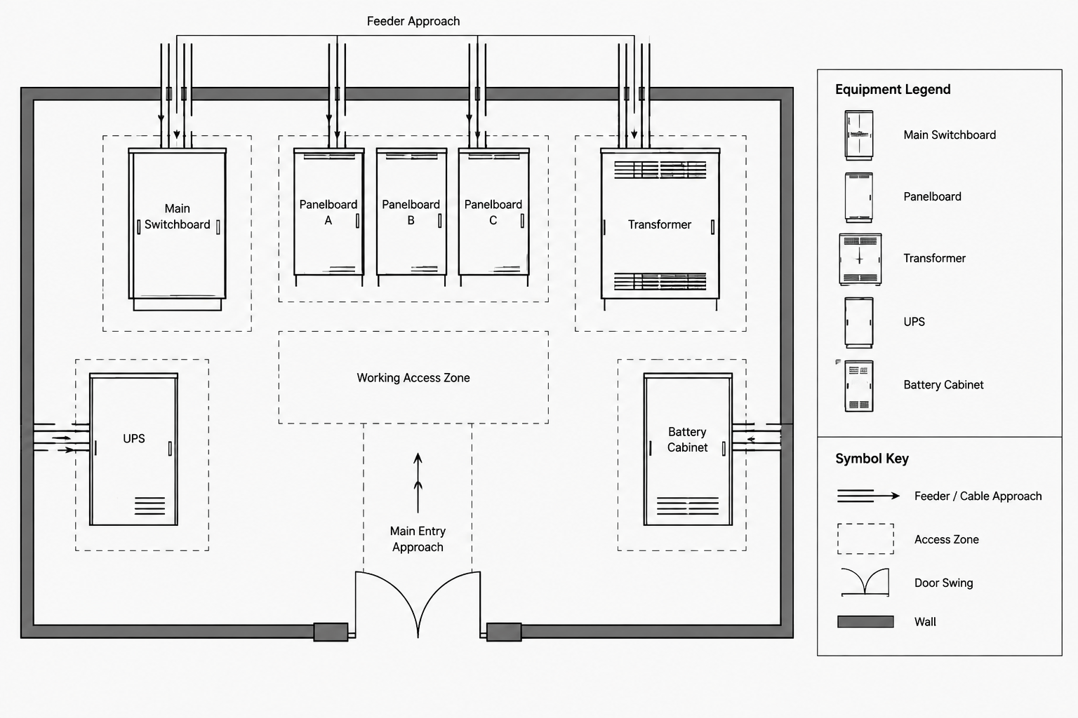
An effective electrical room layout drawing connects electrical design intent with the physical conditions shown by architectural, structural, and trade documents. It should help the project team understand not only where equipment is placed, but also how it will be accessed, connected, coordinated, and identified.
The drafting process therefore depends on information control as much as linework. Equipment outlines, reference backgrounds, access graphics, pathway approaches, and annotations should each communicate whether the information is verified, preliminary, existing, proposed, or reserved for future use.
An electrical room layout drawing does more than show where panels and switchgear are located. It communicates how electrical equipment relates to the room, structure, pathways, doors, and other building systems. When properly coordinated, the drawing helps reviewers identify spatial conflicts before they become field problems.
The layout should not be treated as a collection of generic CAD blocks placed inside an architectural room outline. Each block represents equipment with project-specific dimensions, connection points, access needs, and installation constraints. The drafter’s task is to organize this information into a readable document while making the limits of the available information clear.
What an Electrical Room Layout Drawing Should Communicate
A useful layout allows a reader to understand the equipment arrangement without having to reconstruct it from unrelated sheets. Depending on the project phase and drawing purpose, it may communicate:
- Equipment footprints and orientations
- Equipment identification tags
- Wall, column, door, and structural relationships
- Required working or service areas
- Top, bottom, or side feeder-entry zones
- Conduit, busway, or cable-tray approach directions
- Housekeeping pads or mounting surfaces
- Referenced elevations, sections, schedules, and single-line diagrams
- Areas reserved for future equipment
- Coordination boundaries and unresolved conditions
The amount of detail should match the drawing’s purpose. A conceptual arrangement may use preliminary footprints and clearly labeled assumptions. A construction document should be coordinated against current architectural backgrounds, selected equipment information, and applicable project requirements.
Build the Layout from Reliable References
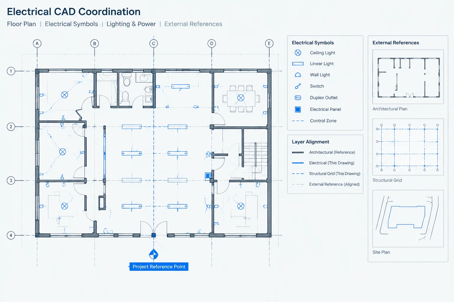
Begin with the current architectural or coordination background rather than recreating the room from memory. Confirm the room boundary, door swings, columns, wall types, shafts, floor openings, and significant overhead conditions. If the background is externally referenced, record its issue or revision status through the project’s established file-management process.
Equipment dimensions should come from verified project information. Generic CAD blocks are useful placeholders, but they should not be assumed to match purchased equipment. Where final information is unavailable, use a clearly identified preliminary envelope and avoid presenting it as an exact manufacturer outline.
Reference hierarchy
| Reference | Information typically obtained | Drafting caution |
|---|---|---|
| Architectural plan | Room geometry, doors, walls, and room identification | Confirm that the background is current |
| Structural plan | Columns, beams, slabs, pads, and penetrations | Do not infer concealed structural conditions |
| Equipment submittal or outline | Actual footprint, sections, access panels, and entry areas | Verify orientation and configuration |
| Single-line diagram | Equipment relationships and feeder connections | A single-line does not establish physical routing |
| Panel or equipment schedule | Tags, descriptions, and system assignments | Keep identifiers consistent across documents |
| Coordination model or trade drawing | Nearby ducts, pipes, trays, and overhead constraints | Differentiate coordinated information from proposed work |
Use Footprints That Show Orientation and Function
A plain rectangle may communicate overall size, but it rarely communicates enough about orientation. Where relevant, an equipment block can distinguish the front, rear, side access panels, doors, removable sections, or connection zones. These graphics should remain simple enough to read at the plotted scale.
Include a logical insertion point and keep the block geometry at actual drawing size. Avoid resizing a manufacturer-specific block merely to make it fit. Scaling the block can create a misleading footprint and may conceal a real coordination problem.
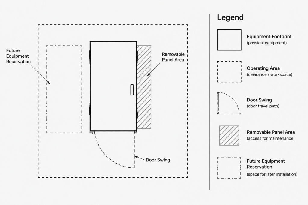
When equipment is composed of multiple sections, consider whether the drawing should show the complete lineup as one object or individual sections. Individual sections can help communicate joints, shipping splits, connection locations, and future additions, while a simplified overall envelope may be sufficient for an early planning plan.
Represent Access and Working Areas Carefully
Electrical equipment often requires clear space for operation, maintenance, inspection, door movement, or component removal. These areas should be treated differently from the physical equipment footprint.
Use a distinct line type, hatch, transparency, or nonplot construction layer to represent access zones. Add a note or legend entry explaining what the graphic means. Do not imply that a generic clearance applies to every condition. Required areas can depend on the equipment, installation, project criteria, manufacturer instructions, and governing requirements.
Several types of space may need separate graphics:
- Normal operating or working area
- Equipment-door swing
- Removable-panel access
- Component pull or replacement path
- Future equipment reservation
- Temporary installation or rigging route
Overlapping access areas should be reviewed rather than automatically accepted. Some overlap may be intentional, while other overlap can make adjacent equipment impractical to operate or maintain.
Coordinate Doors, Circulation, and Equipment Movement
A room can appear adequate until door swings and equipment movement are considered. Show door leaves and swings from the architectural background, and avoid placing equipment where it obstructs normal circulation or interferes with the door operation.
For large equipment, the drawing set may also need to communicate how the equipment reaches its final location. This does not require a complete installation procedure, but it may require coordination of removable openings, corridors, access panels, or reserved movement paths. If this issue is outside the electrical plan’s scope, add an appropriate coordination note or reference a dedicated logistics drawing.
Show Feeder Approaches Without Overloading the Plan
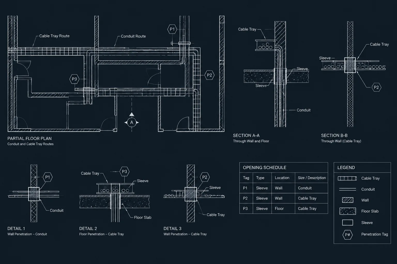
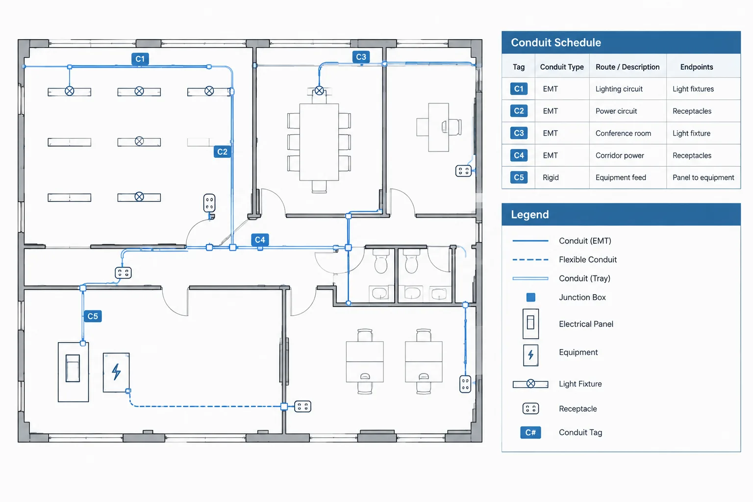
The layout should indicate how major feeders approach equipment, especially where top entry, bottom entry, or side access affects room coordination. A plan may show representative conduit banks, cable tray, busway, trenches, or floor penetration zones. More detailed routing can be placed on enlarged plans, sections, or dedicated pathway drawings.
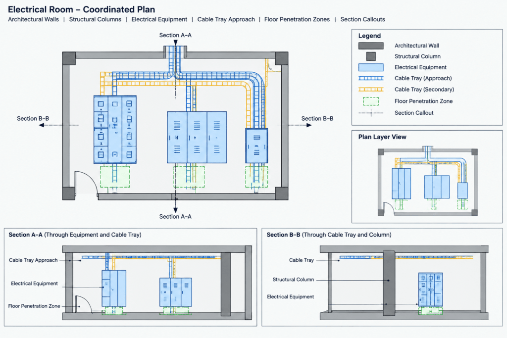
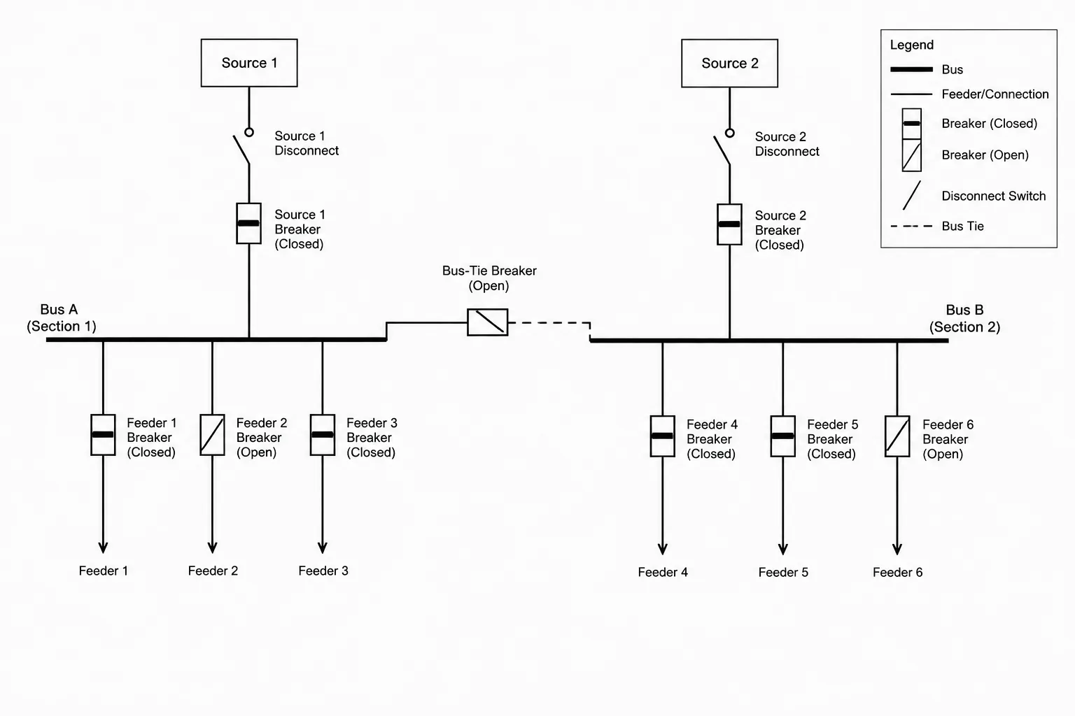
Connection graphics should agree with the single-line diagram, but the two documents serve different purposes. The single-line explains electrical relationships; the room layout explains physical arrangement. A feeder shown between two items on a single-line should not be interpreted as a physical routing instruction.
Use sections or elevations when plan view cannot explain vertical relationships. Typical reasons include overhead tray crossings, wall-mounted equipment above floor-mounted equipment, low structural elements, or top-entry feeder arrangements.
Apply a Clear Tagging and Layer Strategy
Each major item should carry the same identifier used on the single-line diagram, schedules, and related plans. Tags should be positioned consistently and should not obscure access zones or connection points. If a lineup has an overall name plus section identifiers, establish a clear hierarchy.
A practical layer structure can separate:
- Equipment outlines
- Equipment tags and annotations
- Access or service zones
- Feeder and pathway graphics
- Future equipment
- Architectural backgrounds
- Structural coordination information
- Demolition or existing conditions
Layer names and plotting behavior should follow the project’s CAD standard. The goal is not to maximize the number of layers, but to let users isolate information, control lineweight, and distinguish new, existing, future, and reference content.
Add Sections, Elevations, and Enlarged Details Where Needed
An electrical room plan is often most useful when paired with at least one coordinated vertical view. Elevations can show stacked equipment, mounting relationships, wall space, and overhead pathways. Sections can explain slab penetrations, trenches, pads, or conflicts above a lineup.
Place section and elevation callouts where they can be found easily. The viewing direction should be unambiguous, and referenced views should use the same equipment tags as the plan. Avoid redrawing the room independently in each view without a coordination method; disconnected graphics are more likely to drift apart during revisions.
Run a Drawing Coordination Check
Before issue, compare the electrical room layout with related documents. A focused check should confirm:
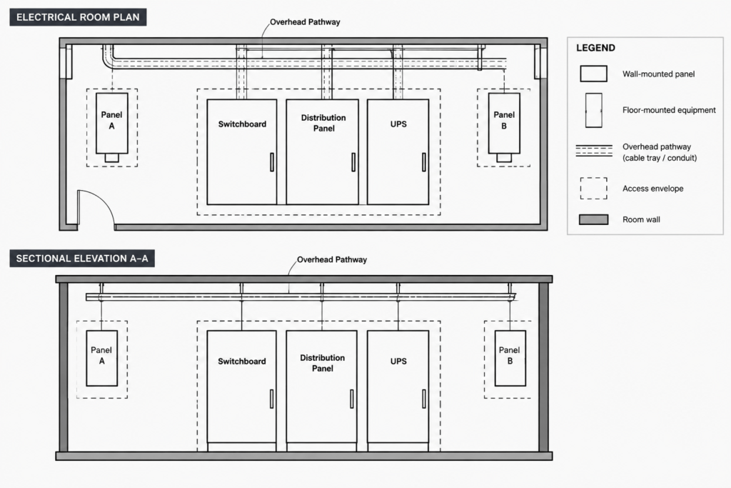
- Room name and location match the architectural plan
- Equipment tags match schedules and single-line diagrams
- Footprints reflect the latest verified information
- Front and rear orientations are clear
- Doors and access panels can be interpreted correctly
- Access-zone graphics have a defined meaning
- Feeder approaches agree with pathway drawings
- Floor and wall penetrations are referenced where required
- Sections and elevations use consistent geometry
- Existing, new, relocated, and future items are distinguishable
- Notes identify preliminary or unverified conditions
- Revision clouds and deltas follow the project workflow
Also review the sheet at its intended plotting scale. Dense hatching, small tags, and overlapping linework may look acceptable in model space but become unreadable on a printed or reduced sheet.
Common Drafting Problems to Avoid
Using generic blocks as final equipment outlines
A generic block can support early planning, but it should be replaced or verified when project-specific information becomes available. Clearly label preliminary envelopes so readers do not mistake them for final dimensions.
Showing only the equipment footprint
A footprint without orientation, access zones, or feeder-entry information provides limited coordination value. Add only the functional graphics needed to explain how the equipment relates to the room.
Ignoring vertical coordination
A clear floor plan can still hide overhead conflicts. Use elevations, sections, or coordinated model views to review trays, conduits, ducts, piping, beams, and ceiling conditions.
Letting tags drift between drawings
Inconsistent identifiers make it difficult to connect the physical plan to the electrical distribution concept. Treat the equipment tag as a shared data point across plans, schedules, diagrams, and details.
A Layout Is a Coordination Document, Not Just a Plan View
The best electrical room layout drawing combines reliable footprints, readable access graphics, consistent tags, pathway information, and well-chosen vertical views. It also distinguishes verified information from assumptions. CAD blocks can accelerate the drafting process, but they do not replace review of actual equipment data and project requirements.
Before a layout is used for construction or procurement coordination, its dimensions, clearances, access provisions, and connection locations should be verified by the responsible project professionals against current manufacturer information and applicable requirements.
Make Information Status Visible
A coordinated layout should allow reviewers to distinguish confirmed information from assumptions without searching through unrelated correspondence. Use the project’s approved notes, layer conventions, line types, or status labels to identify preliminary footprints, pending connection locations, unresolved penetrations, and other conditions awaiting confirmation.
Avoid using graphical precision to imply certainty. A sharply drawn equipment outline can still be preliminary. When the source information is incomplete, identify the envelope and its status directly rather than allowing readers to interpret it as a verified manufacturer outline.
Separate Design Geometry from Reference Geometry
Architectural and structural backgrounds provide essential context, but they should remain distinguishable from electrical design content. This separation helps users isolate equipment, pathways, access zones, and annotations while preserving the ability to review walls, doors, columns, and openings.
When a background changes, review the electrical arrangement rather than simply reloading the reference. A shifted wall, revised door swing, added column, or changed opening can affect equipment orientation, circulation, pathway approaches, and the validity of related sections.
Plan the Drawing Handoff
Before issuing the layout, confirm that another qualified user can understand its scope without relying on the drafter’s memory. The sheet should identify the represented room, equipment tags, view references, information status, and relevant coordination boundaries. Unresolved items should be documented through the established project workflow rather than hidden by incomplete linework.
Keep the CAD file organized for later revisions. Consistent blocks, layers, insertion points, tags, and reference files make it easier to update equipment information without disconnecting the plan from schedules, diagrams, elevations, and pathway drawings.
Electrical Room Layout Drawing FAQ
Can a generic electrical CAD block be used in a room layout?
Yes, as a clearly identified placeholder during preliminary planning. It should not be presented as a verified equipment outline unless its geometry, orientation, access features, and connection information have been checked against current project data.
What is the difference between an equipment footprint and an access zone?
The footprint represents the physical area occupied by the equipment. An access zone represents space associated with operation, service, door movement, component removal, or another defined coordination purpose. The drawing should use different graphics for these conditions and explain them in the legend or notes.
Should feeder routing match the single-line diagram?
Equipment identities and electrical relationships should remain consistent, but a single-line diagram does not define physical routing. The room layout, pathway drawings, sections, and coordinated trade information are used to communicate the physical approach.
When should an elevation or section be added?
Add a vertical view when the plan cannot clearly show mounting relationships, overhead pathways, entry zones, penetrations, stacked equipment, or structural constraints. The view should use the same equipment identifiers and coordinated geometry as the plan.
How should unresolved coordination items be shown?
Identify them with the project’s approved notes, issue tracking, layer conventions, or revision workflow. The drawing should state what remains preliminary or unverified instead of implying that the condition has been resolved.
Does a coordinated CAD layout confirm that the room is ready for construction?
No. The drawing supports coordination, but current equipment information, project requirements, access provisions, connection locations, and related building conditions still require review by the responsible project professionals.






Leave a Reply
You must be logged in to post a comment.