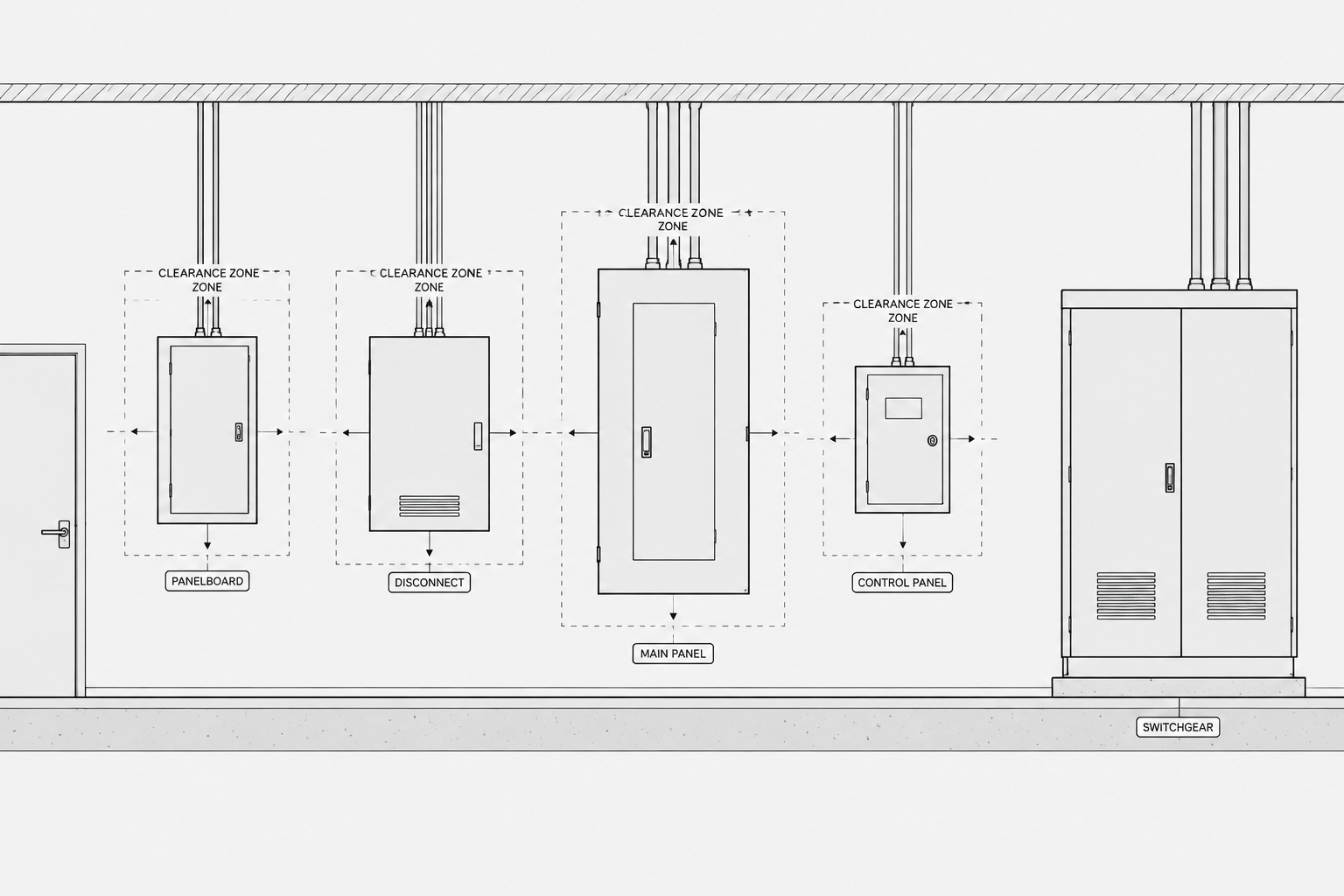
Electrical equipment elevations translate plan-based layouts into coordinated vertical views. They help drawing users understand lineup order, mounting relationships, pathway approaches, architectural constraints, and the connection between equipment tags and other project documents.
This guide explains a practical CAD workflow for building readable elevations from verified inputs. It also highlights how to manage generic blocks, drawing layers, references, dimensions, and revisions without implying that preliminary geometry represents approved equipment.
Electrical floor plans show where equipment is located, but they do not always communicate how that equipment occupies a wall, aligns vertically, or interfaces with nearby building elements. An electrical equipment elevation adds this missing view. It can clarify the arrangement of panels, switchboards, control enclosures, transformers, disconnects, metering equipment, cable pathways, and related accessories.
A useful elevation is more than a collection of front-view CAD blocks. It should connect the physical arrangement to equipment tags, plans, schedules, diagrams, and coordination requirements. The drafting workflow below focuses on producing clear documentation without treating a generic block or drawing as approved for construction.
What Is an Electrical Equipment Elevation?
An electrical equipment elevation is an orthographic view looking horizontally at a wall or equipment lineup. Unlike a floor plan, which is viewed from above, an elevation shows vertical relationships such as mounting order, enclosure height, conduit entry direction, wall features, and separation between adjacent items.
Elevations are especially useful where plan symbols become crowded or where vertical arrangement affects coordination. Depending on the project, they may appear on electrical enlarged-plan sheets, equipment-layout sheets, details sheets, or multidisciplinary coordination drawings.
| Drawing view | Primary purpose | Typical information |
|---|---|---|
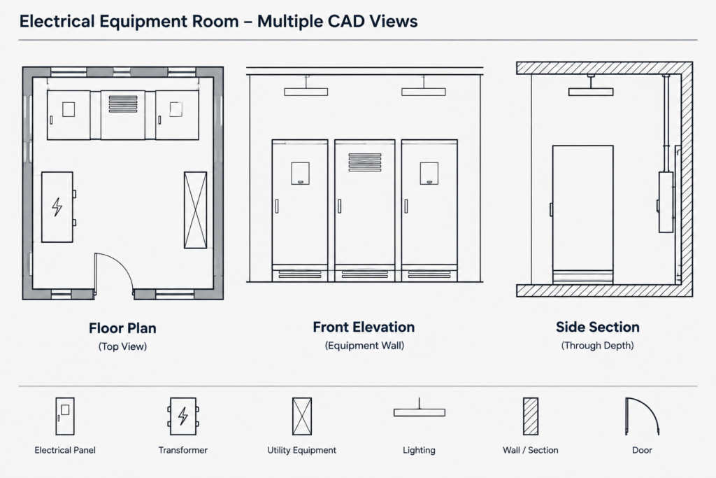
| Floor plan | Shows horizontal location | Equipment footprint, room position, access approach, routing |
| Elevation | Shows the front or side arrangement | Vertical placement, lineup order, tags, wall relationships |
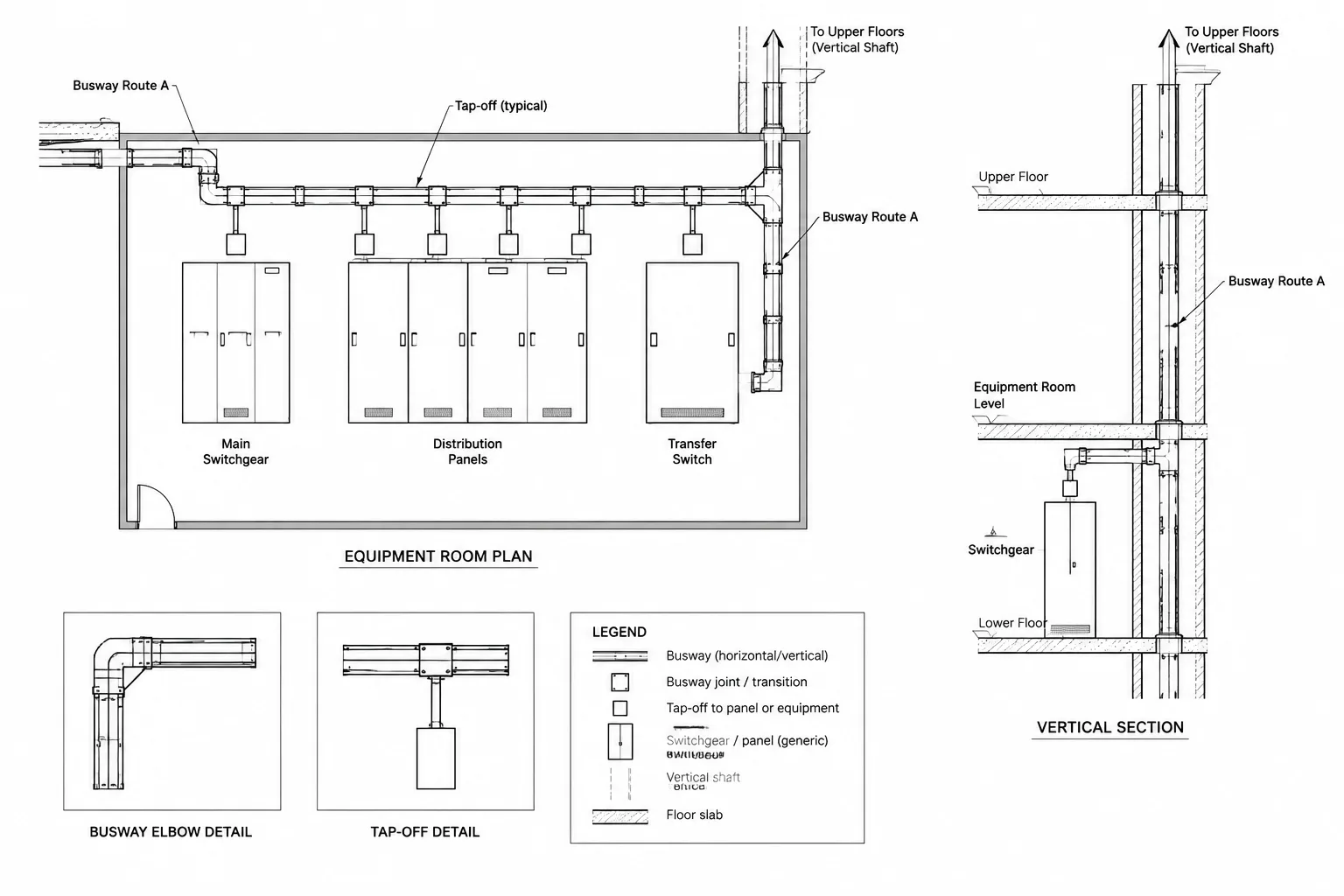
| Section | Shows a cut through an assembly or room | Depth, overhead conflicts, floor or wall construction, routing zones |
| Detail | Explains a focused condition | Supports, interfaces, entries, mounting concepts, references |
Collect Verified Inputs Before Drafting
Start with coordinated project information rather than selecting visually convenient blocks. Generic CAD geometry can establish a placeholder, but final outlines and relationships should be based on verified design documents.
Useful inputs may include:
- The latest architectural room plan and wall elevations
- Equipment schedules and project equipment tags
- Single-line or riser diagrams showing system relationships
- Manufacturer documentation for the selected or scheduled equipment
- Structural information affecting walls, housekeeping pads, or supports
- Mechanical and plumbing layouts for nearby services
- Cable tray, conduit, and underground-entry information
- Project criteria for access, operation, maintenance, and replacement
Where final equipment has not been selected, label the geometry as diagrammatic or preliminary according to the project documentation practice. Avoid presenting assumed dimensions as verified product data.
Choose the Elevation Direction Deliberately
The elevation direction should be identifiable from the floor plan. Add a view marker, callout, or keyed reference showing where the viewer is standing and which direction the viewer faces. This prevents mirrored lineups and confusion about left-to-right equipment order.
For equipment located on multiple walls, create separate labeled elevations. A single unfolded elevation can be useful in some coordination drawings, but it must clearly indicate wall transitions. If equipment depth, overhead pathways, or rear access is important, supplement the front elevation with a side elevation or section.
A Practical CAD Drafting Workflow
1. Establish the architectural context
Use a controlled architectural background or trace only the room elements needed to understand the installation context. Show relevant floors, walls, doors, ceilings, columns, curbs, pads, and openings. Keep background linework visually lighter than the electrical equipment.
Do not redraw the entire architectural model into the electrical file. Referenced backgrounds are generally easier to update and reduce duplicate geometry, provided the project base point and drawing coordinates remain coordinated.
2. Create a clear datum
Include a recognizable floor or mounting reference so vertical placement can be interpreted. If the drawing uses project elevations or level names, coordinate them with the architectural documents. Do not introduce an independent datum that looks official but cannot be reconciled with the rest of the set.
3. Place verified equipment outlines
Represent the overall enclosure or assembly before adding internal detail. For a lineup, maintain the documented section order and identify divisions between sections where they help explain the arrangement.
Use simplified front views at normal sheet scales. Door seams, handles, meters, vents, or access panels may be shown when they support coordination, but excessive product-like detail can obscure tags and may imply a level of selection that has not occurred.
4. Show adjacent building constraints
Add nearby doors, frames, structural elements, piping zones, ductwork, or other obstacles when they affect interpretation. The elevation should answer practical coordination questions: Can an enclosure door open without colliding with another element? Does a wall-mounted item overlap an architectural feature? Is an overhead pathway entering the intended equipment area?
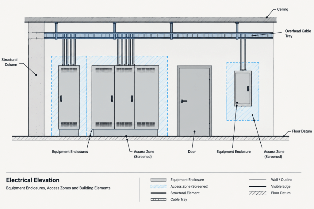
Any access or clearance zone should be drawn from verified project criteria. Use a dedicated non-plot or screened layer when appropriate, and label the zone so it cannot be mistaken for physical equipment.
5. Indicate cable and conduit interfaces
Show whether major pathways approach from above, below, or the side when that information is relevant to coordination. Use diagrammatic conduit or tray lines rather than filling the view with every branch raceway.
Entry locations should not be inferred solely from a generic enclosure block. Coordinate them with the equipment configuration, routing plan, structural conditions, and available product information. Where the route continues beyond the elevation, use a continuation note or reference to the applicable plan or section.
6. Add equipment tags and references
Use the same equipment identifier shown on the floor plan, schedule, and single-line diagram. A concise elevation tag might identify the equipment while directing the reader elsewhere for ratings or circuit data. Repeating large amounts of schedule information creates another location that must be maintained during revisions.
Helpful references may include:
- Equipment tag
- Schedule or diagram reference
- Elevation or section callout
- Associated detail reference
- Room or wall designation
- Routing continuation reference
Organize the Elevation with CAD Layers
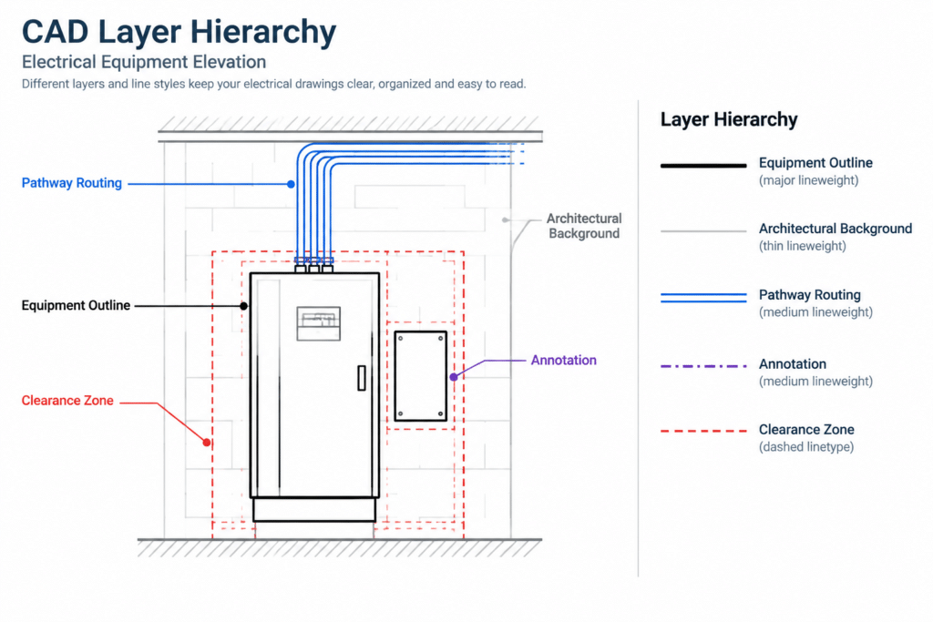
Separating information by function makes elevations easier to revise and plot. Exact layer names should follow the project CAD standard, but a practical structure distinguishes equipment outlines, tags, pathways, clearance graphics, dimensions, references, and background geometry.
| Information group | Drafting treatment | Reason |
|---|---|---|
| Electrical equipment | Strong visible outline | Establishes the primary subject |
| Architectural background | Lighter lineweight or screened plot style | Provides context without competing visually |
| Tags and callouts | Consistent annotation style | Connects the view to other documents |
| Access or service zones | Distinct linetype or light hatch | Differentiates reserved space from physical objects |
| Pathways | Simplified route graphics | Shows interface without unnecessary congestion |
| Dimensions | Dedicated annotation layer | Supports controlled updates and plotting |
Dimension Only What the Drawing Controls
Dimensions should communicate design intent, not duplicate uncertain information. Appropriate elevation dimensions may locate equipment relative to a coordinated datum, wall feature, adjacent enclosure, or support. Product dimensions should come from verified project information rather than a downloaded CAD block.
Avoid long chains of dimensions that mix architectural, structural, and manufacturer-controlled values. Identify the controlling relationship and reference other documents where necessary. If an item must align with another trade’s feature, make that coordination intent explicit instead of relying on coincidental graphic alignment.
Build Reusable Elevation Blocks Carefully
A reusable elevation block library can speed production, but blocks should be classified according to their reliability. Diagrammatic blocks are useful for early layouts. Configurable blocks can represent enclosure families with editable attributes. Project-specific blocks may reflect verified equipment but should not automatically migrate to unrelated projects.
Useful block attributes can include the equipment tag, description, schedule reference, and status. Keep rating data or dimensions out of generic blocks unless the workflow includes a reliable method for validating and maintaining those values.
Use sensible insertion points, such as a consistent bottom corner or centerline reference. This makes block replacement easier when a preliminary outline is updated with coordinated geometry.
Common Elevation Drafting Problems
- Mirrored equipment order: The elevation direction is not linked clearly to the plan.
- False precision: Detailed blocks imply verified products even though equipment selection is incomplete.
- Uncoordinated tags: Equipment identifiers differ between the elevation, plan, schedule, and diagram.
- Missing context: Doors, columns, ceilings, or adjacent systems are omitted even though they affect the arrangement.
- Clearance graphics mistaken for objects: Reserved zones use the same lineweight and layer treatment as equipment.
- Overloaded views: Every conduit, fastener, and enclosure feature is shown at an unreadable scale.
- Orphaned dimensions: Dimensions remain after equipment blocks or backgrounds have moved.
Final Coordination Checklist
Before issuing the drawing, compare the elevation with the current floor plan, equipment schedule, single-line diagram, and architectural background. Confirm that the viewing direction, lineup order, tags, wall relationships, and pathway approaches agree across the set.
- Is the elevation callout visible and unambiguous on the plan?
- Do all equipment tags match the current schedules and diagrams?
- Are outlines based on verified information or clearly identified as diagrammatic?
- Are adjacent doors, walls, ceilings, and structural features current?
- Are access zones distinct from physical objects?
- Are conduit and cable pathway interfaces coordinated with routing drawings?
- Do dimensions identify controlled relationships without repeating uncertain data?
- Are text, lineweights, hatches, and references readable at the intended plot scale?
Well-drafted electrical equipment elevations turn a plan-based arrangement into a coordinated vertical view. Their value comes from consistency and traceability: every outline, tag, pathway, and reference should help the reader connect the physical layout to the rest of the electrical documentation.
Use the Elevation as a Coordination View
An equipment elevation should not function as an isolated illustration. Its primary value is showing relationships that are difficult to interpret on a floor plan while remaining traceable to schedules, diagrams, details, and architectural backgrounds.
When deciding what to include, ask whether each graphic helps identify the equipment, locate it, explain an interface, or reveal a potential conflict. Decorative enclosure detail and duplicated schedule data can usually be omitted when they do not support those purposes.
Separate verified geometry from placeholders
Generic CAD blocks are useful for layout development, but their status should be clear. Use project-approved terminology to distinguish diagrammatic outlines, coordinated equipment, and product-specific geometry. This helps reviewers understand which relationships are dependable and which remain subject to selection or confirmation.
Maintain references during revisions
Equipment elevations can become unreliable when the plan, schedule, or architectural background changes without a corresponding elevation update. Revision reviews should compare equipment order, tags, wall features, pathway directions, and referenced details across the drawing set.
Where the CAD workflow permits, use referenced backgrounds, attributed blocks, consistent layer controls, and managed callouts to reduce manual duplication. These tools do not replace technical review, but they can make inconsistencies easier to identify.
Review the plotted result
Model-space clarity does not guarantee sheet readability. Check the elevation using the intended sheet layout and plot style. Equipment outlines should remain visually dominant, contextual geometry should be recognizable without competing with the subject, and clearance graphics should be unmistakably different from physical objects.
The completed view should communicate arrangement and coordination intent without creating unsupported precision. Final dimensions, access requirements, mounting conditions, and equipment interfaces must remain tied to verified project information.
Frequently Asked Questions
What is the difference between an equipment elevation and a floor plan?
A floor plan shows equipment location from above, while an elevation shows the arrangement as viewed horizontally. The elevation is better suited to communicating vertical alignment, lineup order, wall relationships, and pathway approaches.
Can a generic CAD block be used in an electrical equipment elevation?
Yes, as a diagrammatic or preliminary representation. It should not be treated as verified product geometry unless its outline and relevant features have been checked against current project information.
Should ratings and circuit information appear on the elevation?
Only information needed to identify or coordinate the equipment should be repeated. Detailed electrical data is often better maintained in schedules or diagrams, with the elevation using consistent tags and references to connect those documents.
When is a section needed in addition to an elevation?
A section is useful when depth, overhead routing, wall construction, support conditions, or front-to-back conflicts cannot be understood from the elevation. The section should be referenced clearly from the applicable view.
How should access or service zones be shown?
Use a visually distinct drafting treatment and label the area so readers do not confuse it with physical equipment. The zone must be based on verified project criteria rather than assumptions taken from a generic block.
How can mirrored equipment lineups be avoided?
Connect every elevation to an unambiguous plan marker that establishes the viewing direction. Then compare the left-to-right equipment order between the plan, elevation, schedules, and related diagrams during review.




Leave a Reply
You must be logged in to post a comment.