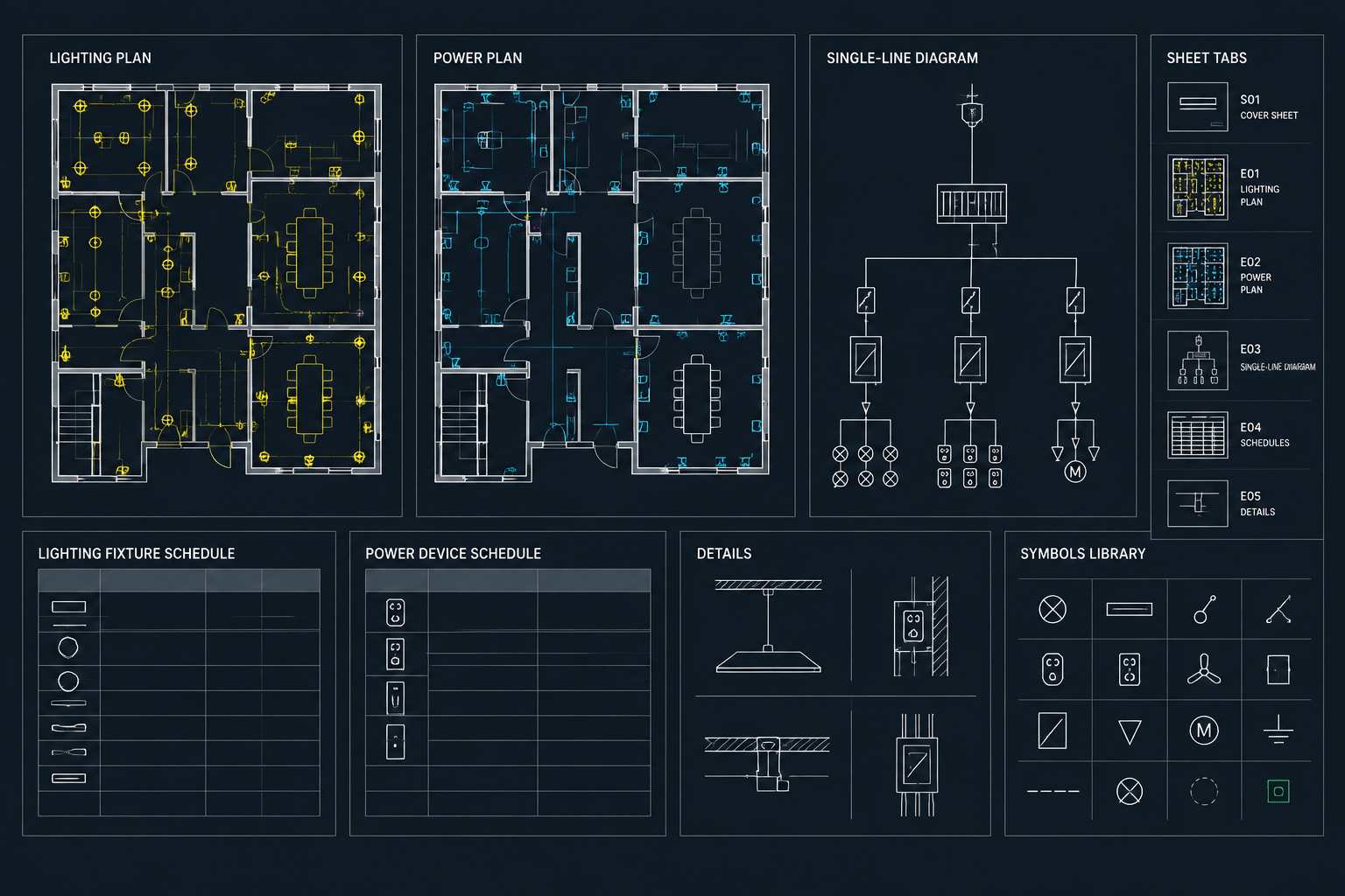
To organize an electrical drawing set effectively, treat the package as a connected information system rather than a stack of individual sheets. Readers should be able to start with the drawing index, locate the appropriate plan, and follow tags or callouts to related diagrams, schedules, enlarged views, and details.
The guidance below focuses on drawing hierarchy, naming consistency, cross-references, matchlines, file relationships, and quality-control practices. These principles can support projects of different types without imposing a universal sheet sequence.
A well-organized electrical drawing set does more than place sheets in a logical order. It helps readers move between floor plans, diagrams, schedules, enlarged views, and installation details without guessing where related information is located. It also gives the CAD team a stable framework for managing files, view references, revisions, and plotting.
Drawing-set structure should reflect the project scope and the documentation requirements established by the design team. There is no universal sheet sequence that fits every project. However, a consistent hierarchy and reliable cross-referencing method can make almost any electrical package easier to read and maintain.
What Belongs in an Electrical Drawing Set?
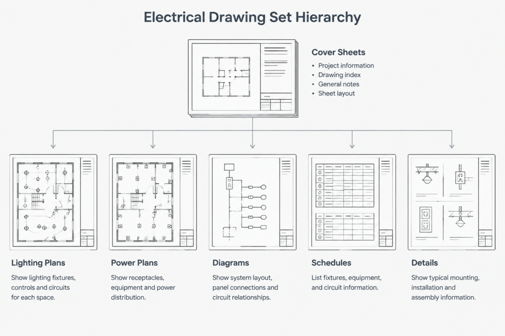
An electrical set may contain several types of information, each serving a different purpose. Small projects may combine these categories on a few sheets, while larger projects may separate them into dedicated groups.
| Drawing category | Primary purpose | Typical coordination relationships |
|---|---|---|
| Cover and reference sheets | Introduce the electrical package and explain its graphic language | Drawing index, abbreviations, symbols, notes, and references |
| Site or overall plans | Show exterior systems, service relationships, or broad distribution routes | Civil backgrounds, utility information, building plans, and diagrams |
| Lighting plans | Document luminaires, controls, circuiting, and related annotations | Reflected ceiling plans, room layouts, control diagrams, and schedules |
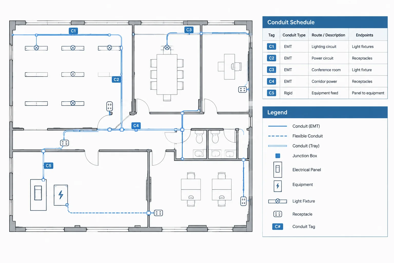
| Power plans | Show receptacles, equipment connections, panels, and branch-circuit intent | Equipment schedules, architectural plans, mechanical plans, and panel schedules |
| Special-system plans | Document systems that require their own symbols, pathways, or device layouts | Technology, security, fire alarm, communications, and specialty consultant drawings |
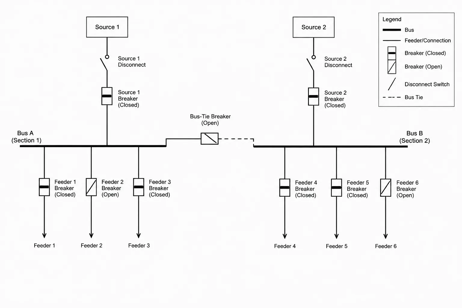
| Single-line and riser diagrams | Explain system hierarchy and connectivity that may not be clear in plan view | Equipment tags, feeders, panels, service equipment, and floor plans |
| Schedules | Present structured equipment, panel, fixture, or connection information | Plan tags, diagram identifiers, specifications, and equipment data |
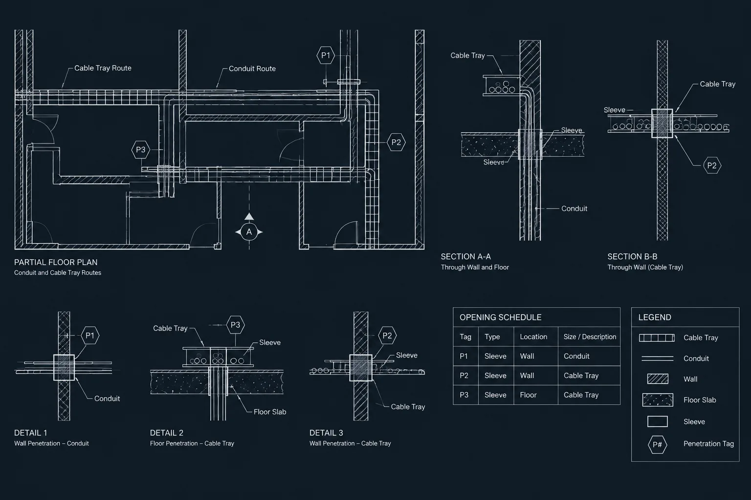
| Details and enlarged views | Clarify arrangements or interfaces that cannot be communicated at the main plan scale | Plan callouts, sections, elevations, equipment layouts, and notes |
Build a Hierarchy Before Creating Sheets
Begin by listing the electrical views and information required for the project. Group them by function rather than immediately assigning sheet identifiers. This prevents the sheet list from becoming a collection of unrelated layouts created as needs arise.
A practical planning outline might separate general information, building plans, system diagrams, schedules, and details. Within the plan group, views can be divided by building, level, area, phase, or system. The selected hierarchy should match how users will search for information.
For example, a multilevel building may be easiest to navigate when lighting and power plans follow the same level sequence. A campus project may be clearer when sheets are grouped first by building. The best approach is the one applied consistently throughout the package.
Create a Sheet Planning Matrix
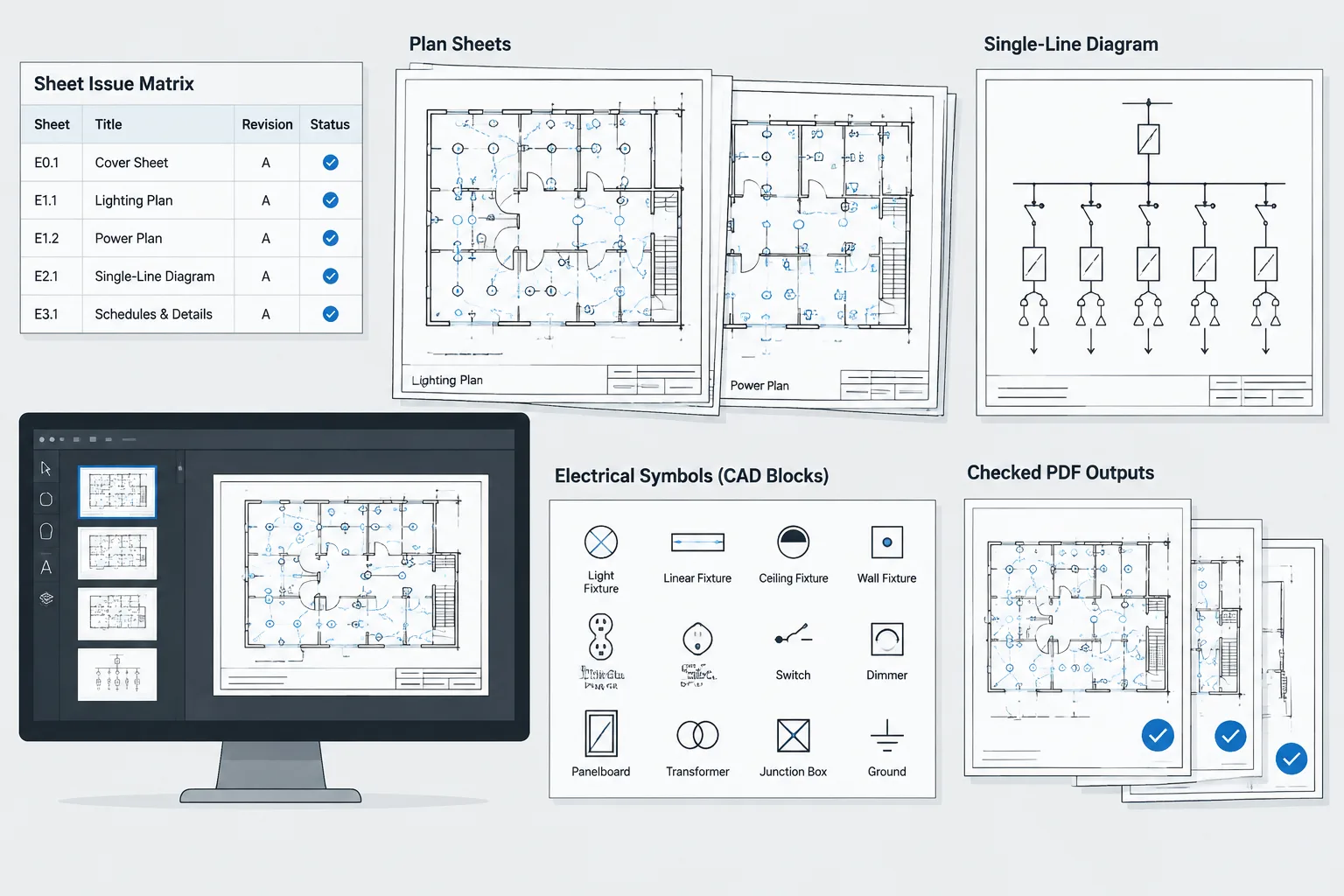
Before laying out title blocks, create a simple planning matrix with columns for the proposed sheet identifier, sheet title, view type, area or level, source CAD file, background reference, and related sheets. This internal tool can expose missing views and naming conflicts early.
The matrix can also identify information that appears in more than one place. Repeated information is not always wrong, but each occurrence should have a defined purpose and a clear source of record.
Use Sheet Identifiers and Titles Consistently
A sheet identifier is most useful when its structure communicates where the sheet belongs in the set. The project team may use discipline designators, drawing-type groups, sequence fields, or other office conventions. Whatever system is selected, it should remain stable unless the project documentation manager approves a change.
Sheet titles should describe content in the same language used elsewhere in the set. Avoid switching between terms such as power plan, receptacle plan, and device plan unless the sheets genuinely show different scopes. Similar titles should follow the same word order so they sort and scan predictably.
- Use one preferred name for every building, level, area, and electrical system.
- Keep sheet identifiers unique across the complete project package.
- Avoid titles that are too broad to distinguish one view from another.
- Coordinate title-block descriptions with the drawing index.
- Reserve space in the sequence for likely additions when the project workflow permits it.
Connect Plans, Diagrams, Schedules, and Details
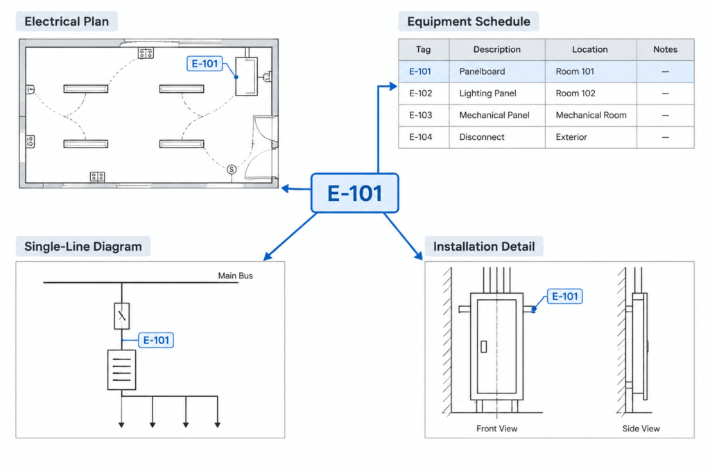
Organization is not complete until related information is connected. A device shown on a plan may also appear in a schedule, a single-line diagram, an enlarged layout, or a detail. Consistent tags and references allow the reader to follow that information chain.
Plan-to-Schedule Relationships
Equipment and device tags on plans should match the identifiers used in associated schedules. If a schedule is located on another sheet, provide a clear reference where needed. The schedule title should make its scope apparent, especially when several schedules contain similar equipment categories.
Plan-to-Diagram Relationships
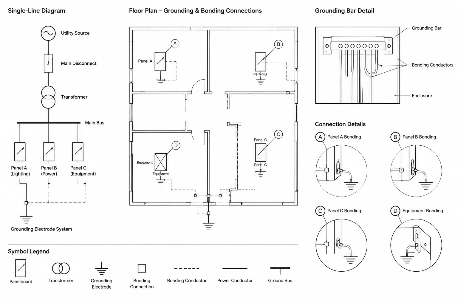
Panels, transformers, generators, distribution equipment, and other system elements may appear both in plan view and on a diagram. Their identifiers should remain consistent even though the symbols and graphic scale differ. A diagram symbol represents system function; a plan block represents physical location or footprint. These graphics should not be treated as interchangeable merely because they refer to the same equipment.
Plan-to-Detail Relationships
Use detail callouts where a reader needs another view to understand the documented arrangement. The callout should identify both the detail and its destination sheet. If a detail is moved, deleted, or renumbered, every referring callout must be reviewed.
Manage Matchlines and Continuation References
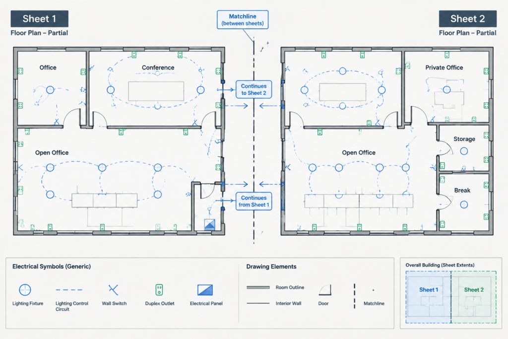
Large floor plans are often divided across multiple sheets. Matchlines should clearly show where one view stops and the next begins. Continuation text should use the exact destination sheet identifier and, when helpful, the destination view or area name.
Place matchlines so significant rooms or equipment are not split unnecessarily. When a split cannot be avoided, decide which sheet owns the primary annotation. Duplicating tags, circuit information, or keynote markers on both sides without a defined rule can create conflicts during revisions.
Adjacent sheets should use compatible backgrounds, orientation, annotation conventions, and visible limits. A reader following a route across a matchline should not encounter an unexplained shift in naming or graphic presentation.
Coordinate CAD Files with the Sheet Structure
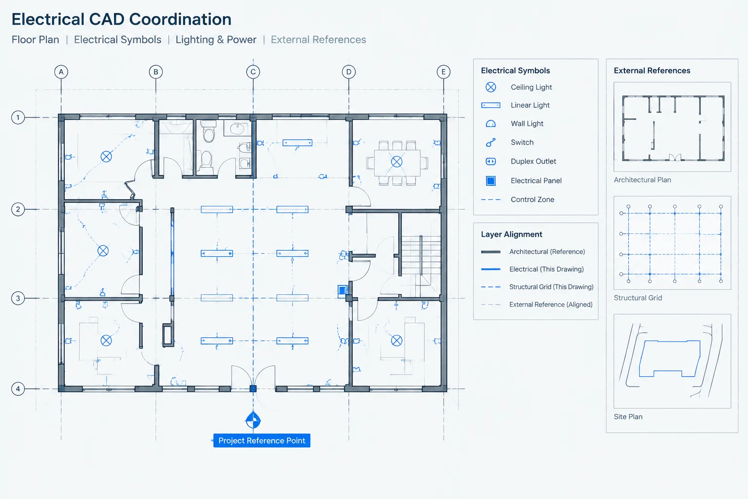
The sheet index and the CAD file structure do not have to be identical, but their relationship should be understandable. A model file may contain plan information referenced into several sheet files, or a sheet file may combine multiple referenced models. Document the approach so another drafter can identify the source of displayed geometry.
Useful file-management practices include:
- Separate reusable model information from sheet-specific annotation when appropriate.
- Use stable file names that do not depend on informal personal abbreviations.
- Keep architectural and consultant backgrounds distinguishable from electrical content.
- Avoid placing unique project data inside generic library block files.
- Confirm that reference paths and plotting dependencies work outside the original drafter’s workstation.
- Archive issued files in a way that preserves the relationship between models, references, and plotted sheets.
Design the Drawing Index as a Navigation Tool
A drawing index should reflect the actual issued package rather than an early planning list. Titles and identifiers must match the title blocks. If sheets are intentionally omitted from an issue, the index should follow the project’s established method for communicating their status.
For long sets, group index entries by discipline section, system, building, or drawing type. The grouping should mirror the set itself. This makes the index useful for navigation rather than merely proving that a sheet exists.
Common Organization Problems
- Orphaned references: A callout points to a view that was moved, renamed, or deleted.
- Duplicate identifiers: Two sheets, details, or equipment items use the same tag.
- Inconsistent area names: The plan, title block, index, and matchline use different names for one location.
- Mixed scope: A sheet title suggests one system while the view includes unrelated content without explanation.
- Unclear source ownership: The same note or data appears on several sheets, but no location is treated as authoritative.
- Late sheet expansion: New sheets are inserted without checking references, index order, or neighboring view titles.
Final Drawing-Set Review
Review the package from the reader’s perspective rather than checking each sheet in isolation. Start at the index, locate a representative plan, follow an equipment tag to its schedule, trace the system to a diagram, and open a referenced detail. This navigation test often finds coordination problems that a visual CAD review misses.
Also compare title blocks with the index, verify matchline destinations, inspect detail callouts, and confirm that the latest backgrounds appear throughout the set. Automated fields and block attributes can reduce manual entry, but they do not replace a deliberate review of the published output.
Effective electrical drawing set organization creates a visible information path. When sheet hierarchy, titles, tags, references, and CAD files support one another, users can find related information quickly and the drafting team can revise the package with fewer coordination errors.
Make Navigation Rules Part of the Project Workflow
Drawing organization is easier to maintain when the team defines navigation rules before production expands. Record the preferred terminology for buildings, levels, areas, systems, sheets, and views in the project documentation plan. The same vocabulary should appear in file names, title blocks, indexes, matchlines, schedules, and coordination records.
Responsibility for shared information should also be clear. When an equipment identifier, note, or diagram reference changes, the team should know which drawing or data source controls the update and which related views require review. This reduces the risk of correcting one sheet while leaving conflicting information elsewhere.
Review Common Reader Paths
A useful quality check is to test the set through the tasks different readers are likely to perform. The goal is not merely to confirm that a reference exists, but to verify that the reference leads to the expected information without ambiguity.
- Plan navigation: Move from the index to a plan and then across adjoining plan areas.
- Equipment tracing: Follow an equipment tag from its plan location to the relevant schedule and system diagram.
- Detail lookup: Open a referenced detail and confirm that its title and content match the originating callout.
- System review: Compare plan symbols and identifiers with the corresponding single-line or riser representation.
- Revision review: Confirm that renamed, moved, added, or removed views are reflected throughout the index and reference chain.
Separate Sheet Identity from View Identity
A sheet is a published document container, while a view is a plan, diagram, schedule, detail, section, or other presentation placed on that sheet. Keeping these concepts distinct helps when views are moved during layout development. References should identify the destination clearly enough that a reader can find both the sheet and the intended view.
This distinction also improves CAD management. Model content may support several views, while sheet-specific annotation belongs only to a particular published layout. Clear ownership makes later revisions and handoffs easier to understand.
Control Changes Across the Complete Set
Any change to a sheet identifier, title, area name, equipment tag, detail designation, or matchline destination should trigger a search for dependent references. Review both visible annotations and supporting records such as the drawing index, issue list, plotting setup, and sheet-planning matrix.
Before publishing, inspect the plotted output rather than relying only on the working CAD environment. A correctly linked model can still produce an unclear drawing if references are clipped, annotations are hidden, linework is difficult to distinguish, or an index no longer matches the issued package.
Frequently Asked Questions
Is there one correct order for electrical drawing sheets?
No universal sequence fits every project. The order should reflect the project scope, team conventions, and how readers need to move between plans, diagrams, schedules, and details. Consistency is more important than forcing every project into the same structure.
Should lighting and power plans use the same area names?
Yes, when they describe the same project locations. Consistent building, level, and area names help readers compare systems and reduce confusion in indexes, matchlines, backgrounds, and coordination records.
What is the difference between a sheet identifier and a view reference?
The sheet identifier names the published sheet. A view reference identifies a particular detail, plan, diagram, schedule, or other view, often together with its destination sheet. Both should be coordinated when a view is moved or renamed.
How should removed or relocated views be handled?
Review every callout, matchline, index entry, and note that pointed to the previous location. The project team should also apply its established issue-documentation method so readers are not directed to obsolete content.
Can CAD file names differ from sheet identifiers?
They can, provided the relationship remains documented and understandable. A model file may support several sheets, and a sheet may display several referenced files. Stable naming and clear source ownership are essential for coordination and handoff.
What is a practical way to test drawing-set navigation?
Choose representative information on a plan and follow it through every related schedule, diagram, detail, and continuation reference. Then confirm that titles, tags, destinations, and index entries agree in the published output.






Leave a Reply
You must be logged in to post a comment.