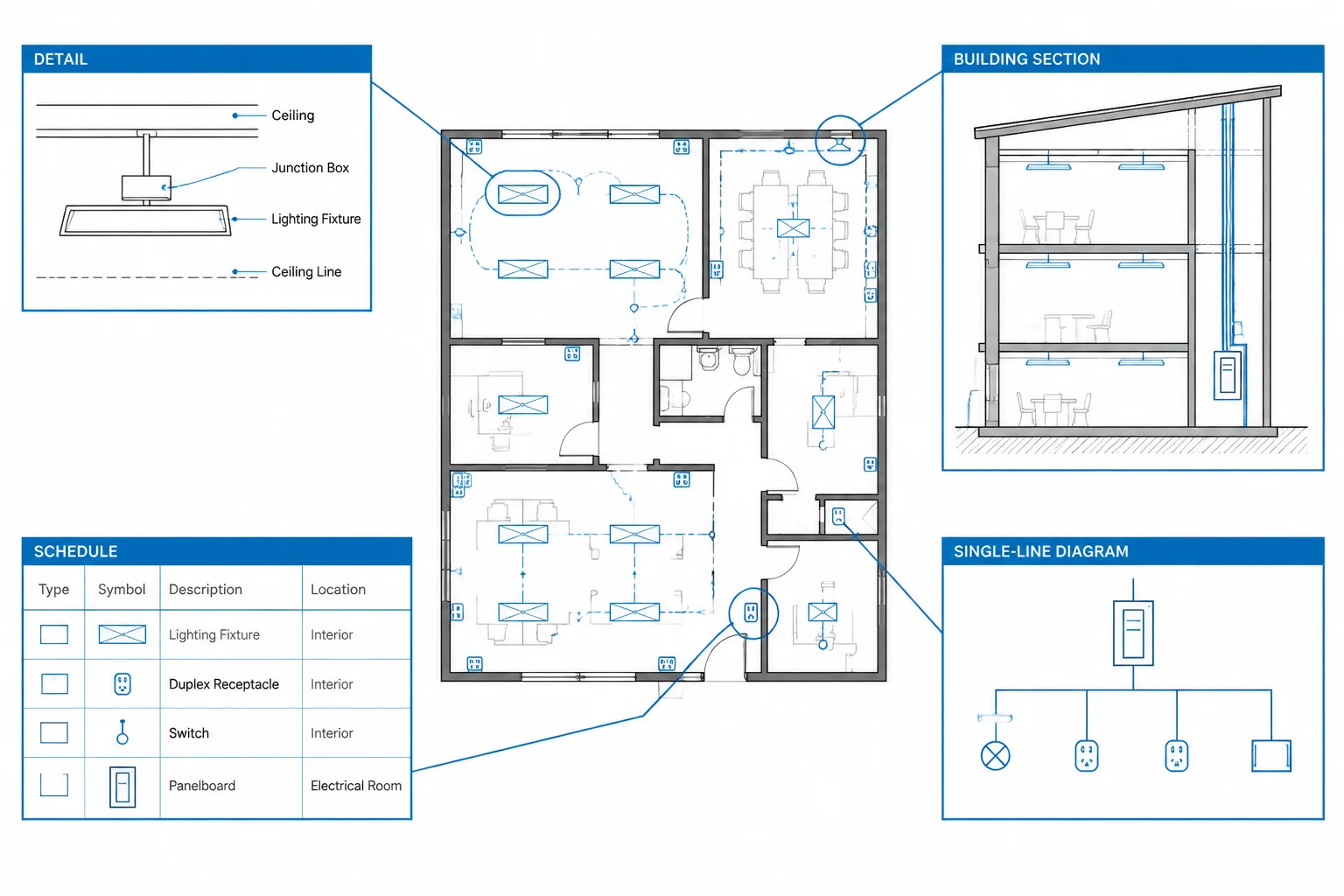
Electrical drawing cross-references help readers follow a condition from its physical location to the supporting view or data that explains it. Effective coordination depends on more than placing a callout: identifiers, destinations, equipment names, and drawing context must remain aligned throughout the document set.
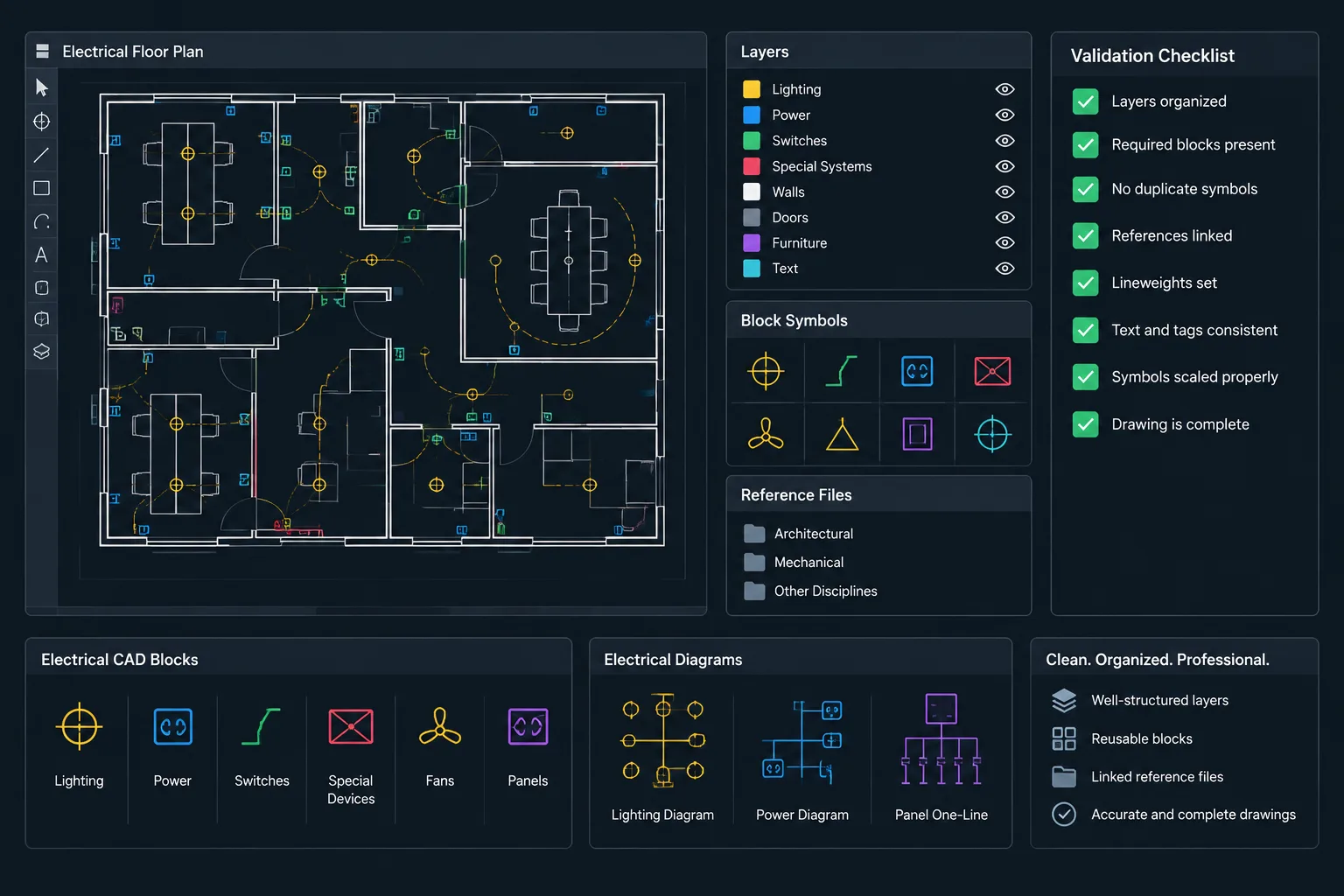
This guide explains how to organize and review references among electrical plans, details, sections, schedules, one-line diagrams, risers, and related discipline drawings. The emphasis is on practical CAD documentation, revision control, and readable navigation rather than any particular software platform.
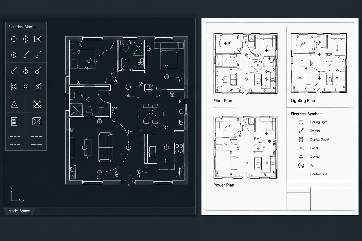
Electrical drawing cross-references connect information that cannot be shown clearly in one view. A floor plan may identify an equipment location, while a referenced detail explains mounting conditions, a section shows vertical relationships, and a single-line diagram documents the electrical connection. When these references are coordinated, readers can move through the drawing set without guessing where supporting information is located.
Cross-references are more than graphic callouts. They form a navigation system for the documents. A reliable system must identify both the destination and the context of the referenced information, remain readable at the plotted scale, and survive sheet reorganization and revisions.
What an Electrical Drawing Cross-Reference Does
A cross-reference directs the reader from one drawing location to related information elsewhere. It may connect views on the same sheet, different sheets in the electrical set, or coordinated documents from another discipline.
Common electrical drawing cross-references include:
- Plan-to-detail callouts for mounting, support, or installation concepts.
- Plan-to-section references where vertical position or routing is important.
- Equipment tags that connect plan symbols to schedules.
- Panel and transformer identifiers coordinated with one-line diagrams.
- Feeder or raceway references connecting plans, risers, and schedules.
- Match-line references between adjacent plan areas.
- Keynotes that direct readers to a numbered or coded note list.
- Continuation references for circuits or routes that leave the current view.
- References to architectural, structural, mechanical, or civil information.
A good cross-reference answers two questions: where should the reader look, and what information should the reader expect to find there?
Reference Types and Their Best Uses
| Reference type | Typical purpose | Coordination concern |
|---|---|---|
| Detail callout | Directs the reader to a larger or more explanatory view | The detail must actually apply to the tagged condition |
| Section callout | Shows a cut direction and vertical or concealed relationships | The viewing direction and section extent must be clear |
| Schedule reference | Connects a device or equipment tag to tabulated information | Identifiers must match exactly across plans and schedules |
| Diagram reference | Connects physical locations to one-lines, risers, or control diagrams | Equipment names and system relationships must remain consistent |
| Match line | Continues a plan across another drawing area | Both sides should identify the corresponding destination |
| Continuation marker | Tracks a circuit, feeder, raceway, or cable route between views | The destination marker should use the same identifier |
| External discipline reference | Points to information controlled by another design discipline | The note should not imply that the electrical drawing controls external content |
Build a Consistent Callout Family
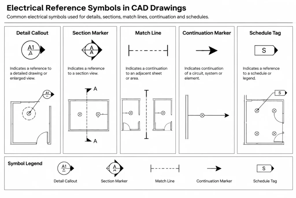
Cross-reference symbols should look related without becoming indistinguishable. A detail callout, section marker, and continuation bubble may share text styles and lineweights, but each should retain a recognizable graphic form.
A practical CAD callout family typically defines:
- A consistent text style and plotted text size.
- A clear location for the view, detail, or note identifier.
- A separate location for the destination sheet identifier when needed.
- A standard leader, arrow, or viewing-direction convention.
- Layer assignments for symbols, leaders, text, and nonplot construction geometry.
- Attribute names that are consistent across related blocks.
Avoid placing permanent sheet information in ordinary linework when it can be stored as editable block attributes. Attributes make references easier to review, update, and extract. Dynamic behavior may also help with orientation or leader placement, but it should not make a symbol difficult to edit in another CAD environment.
Keep the Identifier and Destination Separate
The identifier describes the referenced item, while the destination tells the reader where to find it. Treating these as separate data fields reduces editing errors. If a detail moves to another sheet, the destination can change without renaming the detail itself.
This separation is also useful for quality control. A CAD standards checker, data extraction table, or manual review list can compare destination fields against the current sheet index without interpreting combined free-form text.
Establish the Reference Before Placing the Callout
Do not begin by scattering empty callout bubbles across a plan. First decide what supporting view is required and what question that view will answer. A detail should clarify a recurring or significant condition rather than simply enlarge the same lines shown on the plan.
A useful workflow is:
- Identify the condition that needs additional explanation.
- Select the most appropriate format: detail, section, schedule, diagram, or note.
- Create or reserve the destination view.
- Assign a stable identifier according to the project convention.
- Place the source callout at every applicable location.
- Verify that the destination view contains the promised information.
This approach prevents a common documentation problem: a callout that points to a generic detail that does not match the plan condition.
Coordinate References Across Electrical Drawing Types
Plans and Details
Plan-to-detail references should be placed close to the relevant equipment, device, or route without obscuring geometry. The leader should terminate unambiguously. If one detail applies to several similar conditions, the drawings should communicate whether the reference is typical, limited to selected locations, or supplemented by project notes.
Plans and Sections
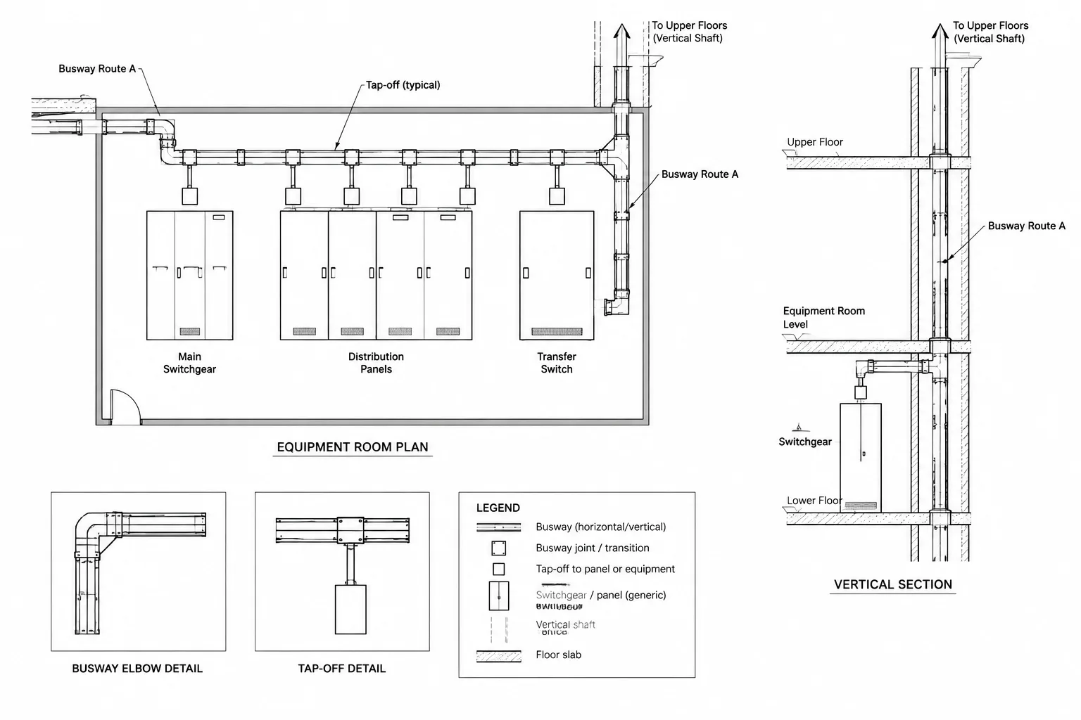
A section marker should communicate where the drawing is cut and the direction of view. This is especially valuable for electrical rooms, ceiling spaces, equipment groupings, wall-mounted assemblies, and congested routing areas. Confirm that the section includes enough surrounding architecture or structure to orient the reader.
Plans and Schedules
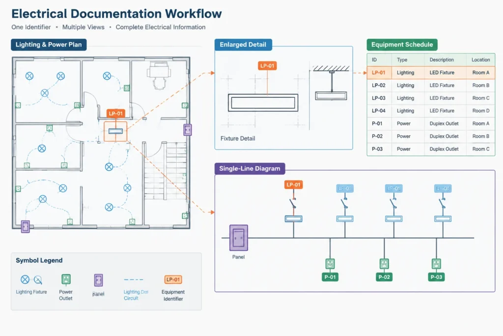
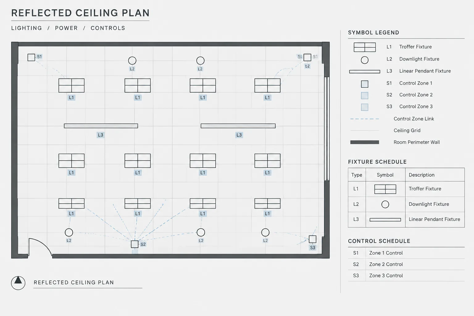
Schedule coordination usually relies on matching identifiers rather than graphic callout bubbles. Device types, equipment names, panel designations, and fixture types must use the same spelling and formatting in both locations. Avoid near-matches that differ only by punctuation, spaces, or informal abbreviations.
Plans and One-Line or Riser Diagrams
The plan shows physical placement, while a one-line or riser diagram shows system relationships. Cross-coordination depends on stable equipment identifiers. If a panel, disconnect, transformer, or other distribution component appears in both views, its designation should remain consistent even though the symbols differ.
Do not force plan symbols and diagram symbols to look identical. They serve different drawing purposes. The shared identifier, not the graphic shape alone, is what connects the views.
Electrical and Other Disciplines
External references require careful wording because another discipline may control the destination information. Rather than duplicating architectural elevations or mechanical equipment details, the electrical documents can reference the coordinated location while retaining electrical connection and identification information in the electrical set.
References to external drawings should be reviewed whenever backgrounds or consultant sheets are reissued. Sheet names, view identifiers, and layout locations can change even when the underlying design intent remains similar.
Manage Cross-References During Sheet Reorganization
Cross-references are vulnerable when details move, sheets are inserted, or the set is divided into packages. Before moving a view, identify every source callout that points to it. After the move, update the destination and verify that no obsolete copy remains at the former location.
A simple reference register can help on larger sets. It may record the source sheet, source location, reference type, destination identifier, destination sheet, and review status. The register does not need to appear in the issued documents; it can function as an internal coordination tool.
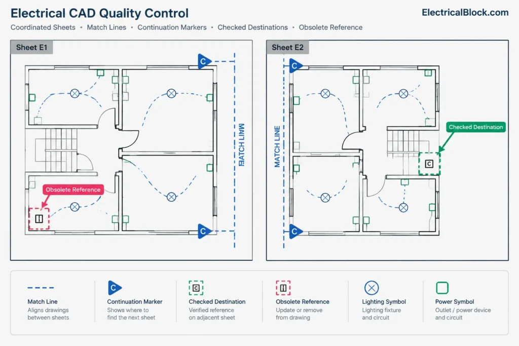
If the CAD platform supports linked view references, use them according to the project workflow, but do not assume automation removes the need for visual review. References may be technically linked and still overlap other annotations, point in a confusing direction, or lead to a view that no longer explains the intended condition.
Layering and Graphic Hierarchy
Place cross-reference graphics on predictable layers so they can be reviewed independently from electrical devices and circuiting. Depending on the office standard, separate layers may be useful for callout symbols, leaders, section indicators, match lines, and reference text.
The plotted hierarchy should keep the electrical design content dominant while making navigation symbols easy to find. Oversized or excessively bold callouts can compete with equipment and circuit information. Callouts that are too light may disappear against screened backgrounds.
Check references in the intended sheet view rather than only at model-space zoom. A symbol that appears clear while editing may become crowded or illegible when plotted.
Cross-Reference Quality-Control Checklist
- Confirm that every callout has a valid destination.
- Confirm that every referenced view is called out where needed.
- Compare equipment identifiers across plans, diagrams, and schedules.
- Check both sides of every match line and continuation reference.
- Remove references to deleted or superseded views.
- Verify that the destination content answers the question implied by the callout.
- Check leaders for clear endpoints and avoid crossing unrelated symbols.
- Review reference text at the final plotting scale.
- Search for placeholder values, empty attributes, and temporary notes.
- Repeat the review after sheets or details are rearranged.
Treat Cross-References as Drawing Data
The most dependable electrical drawing cross-references are managed as coordinated data rather than decorative bubbles. Stable identifiers, structured attributes, consistent layers, and a repeatable review process make references easier to maintain throughout design revisions.
CAD blocks can provide the graphic framework, but the drafter must still verify the relationship between the source condition and the destination information. A well-coordinated reference system helps plans, details, sections, schedules, and diagrams function as one connected electrical document set.
Review the Drawing Set in Both Directions
A useful final check follows each reference forward from the source and then backward from the destination. The forward review confirms that a plan callout reaches the intended detail, section, schedule, or diagram. The reverse review asks whether a reader arriving at that destination can identify the applicable plan condition without relying on guesswork.
This bidirectional review can reveal references that are technically correct but poorly contextualized. Examples include a generic detail with no indication of where it applies, a schedule identifier that appears on multiple unrelated items, or a continuation marker that identifies a destination without clarifying the route being continued.
Define Ownership of Reference Information
Each cross-reference should have a clear source of authority. The electrical team may control equipment designations and diagram relationships, while another discipline controls room names, structural conditions, or equipment configurations. Defining that ownership helps reviewers distinguish an electrical coordination issue from a change that must be resolved in another document.
Duplicating externally controlled information can create conflicts after revisions. Where practical, use the electrical drawings to identify the relationship and required electrical context without recreating an entire view managed elsewhere.
Include References in Issue-Readiness Reviews
Cross-reference review should be part of drawing-set readiness rather than an isolated drafting cleanup task. Before issue, reviewers should look for unresolved placeholders, destinations that were moved, inconsistent equipment names, and callouts obscured by revised backgrounds.
- Navigation check: Confirm that the reader can find the destination without interpreting office-specific shorthand.
- Applicability check: Confirm that the destination represents the condition marked at the source.
- Consistency check: Compare identifiers, terminology, and abbreviations across drawing types.
- Presentation check: Review leaders, symbols, and text in the plotted sheet context.
- Change check: Revisit affected references whenever sheets, views, equipment tags, or backgrounds change.
Treating these checks as part of the normal documentation workflow makes the connected drawing set easier to navigate and reduces the chance that correct design information will be separated by an incorrect reference.
Frequently Asked Questions
What is the difference between a callout and a keynote?
A callout usually directs the reader to another view, sheet, detail, or diagram. A keynote directs the reader to a corresponding note entry. Both require consistent identifiers, but they lead to different kinds of supporting information.
Should a same-sheet reference include a sheet destination?
Follow the project convention and make the destination unambiguous. Even when the referenced view is nearby, a structured destination field can make later sheet reorganization easier to manage.
Do plan symbols and one-line symbols need to match graphically?
No. Plan and diagram symbols serve different communication purposes. Coordination normally depends on a consistent equipment identifier and system relationship rather than identical graphic forms.
When should cross-references be checked again?
Review them after view moves, sheet reorganization, equipment renaming, background updates, package separation, and other revisions that may affect either the source or destination.
Can linked CAD references replace manual quality control?
Linked fields and view references can reduce routine editing, but they do not confirm that a destination is relevant, readable, or complete. A visual and contextual review is still necessary.
How should an unresolved destination be handled?
Use the project team’s controlled coordination process rather than leaving an ambiguous issued callout. Temporary markers should be easy to locate during review and resolved before the drawing set is released.








Leave a Reply
You must be logged in to post a comment.