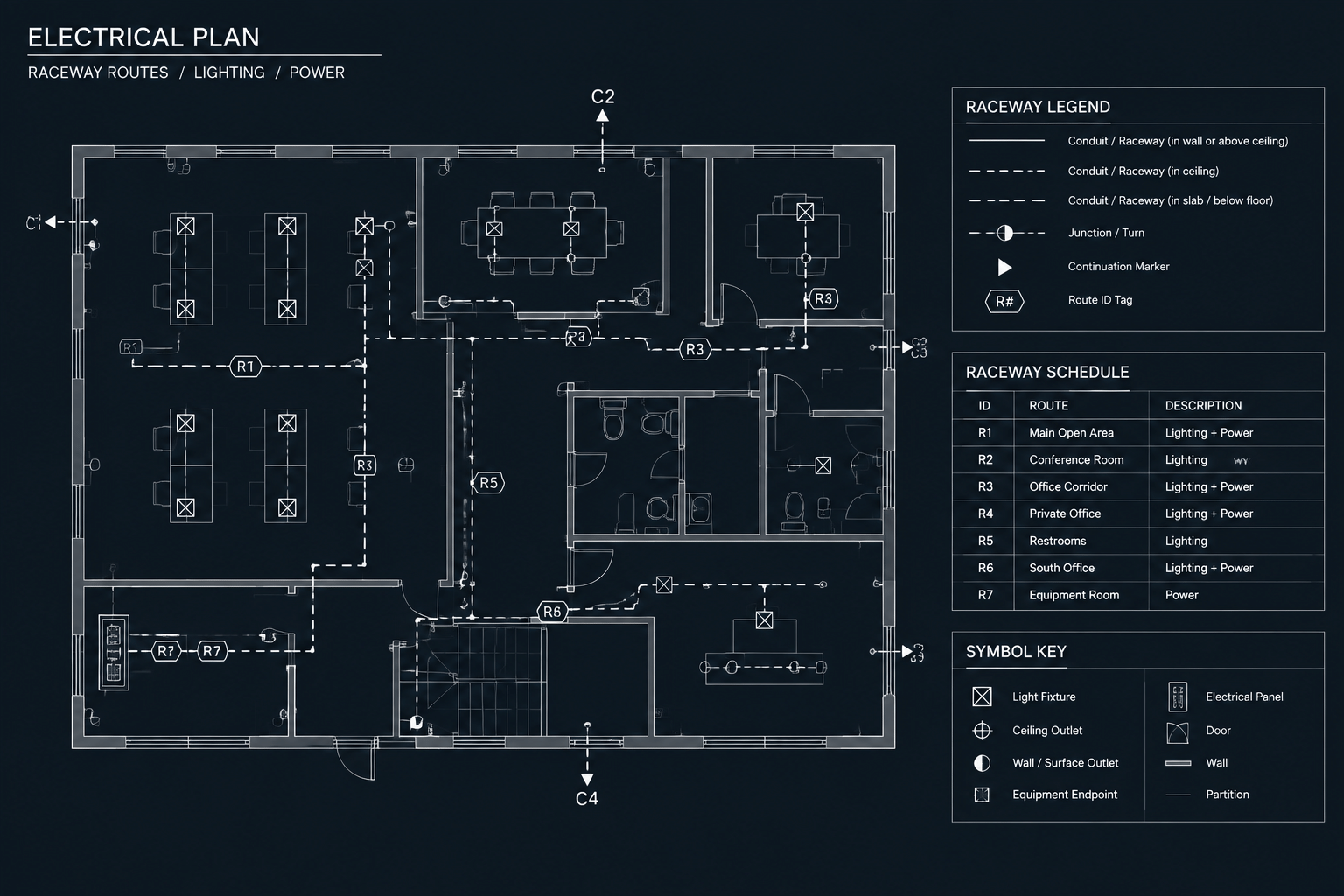
Electrical raceway tagging in CAD turns route linework into traceable documentation. A consistent identifier allows drafters and reviewers to follow the same pathway across plans, enlarged views, sections, diagrams, and schedules without placing every route detail beside the line.
The guidance below explains how to structure tags, control CAD blocks, manage continuations, and check the relationship between graphics and schedule records. It is intended as a documentation reference; project-specific raceway design and installation requirements remain subject to review by the responsible project team.
Raceway lines can make an electrical plan look complete while still leaving important questions unanswered. A route may be visible, but reviewers also need to understand where it begins and ends, whether it continues on another sheet, and which schedule or note defines its contents. Electrical raceway tagging in CAD provides that documentation layer.
A good tagging system connects plan graphics with sections, details, equipment, and schedules without forcing every piece of information onto the floor plan. The goal is not to make the drawing denser. It is to give each documented route a stable identity that can be followed through the drawing set.
This guide focuses on drafting and coordination. Raceway types, conductor requirements, routing constraints, and installation details must still be established and verified by the responsible project team.
What a Raceway Tag Should Accomplish
A raceway tag is an identifier attached to a drawn conduit, duct, sleeve, or grouped route. Depending on the project workflow, the tag may point to a raceway schedule, cable schedule, feeder schedule, keynote, or continuation reference.
An effective tag should help a reader determine:
- which route is being identified;
- where the route starts and terminates;
- whether it continues on another plan or drawing type;
- which schedule contains its descriptive information;
- whether several parallel lines are separate routes or part of one grouped pathway;
- and whether the same identifier appears consistently throughout the drawing set.
The tag should identify the route rather than attempt to replace the design documentation associated with it. Loading a small plan label with conductor descriptions, raceway information, source data, destination data, and installation notes usually produces crowded drawings and difficult revisions.
Separate Route Identity from Route Description
One of the most useful documentation decisions is separating the route identifier from the route description. The identifier remains short enough for plans, while the description is maintained in a schedule or note set.
| Information | Best documentation location | Reason |
|---|---|---|
| Unique route ID | Plan tag and schedule | Connects the graphic to its record |
| Origin and destination | Schedule, with plan confirmation | Supports route tracing and quality control |
| Raceway description | Schedule or keyed note | Avoids long labels along the route |
| Circuit or cable association | Relevant schedule or diagram | Keeps related electrical information together |
| Continuation sheet | Local continuation callout | Directs readers at the point where the route leaves the view |
| Typical installation condition | Detail reference | Prevents repeated detail notes on plans |
This division also reduces revision risk. When a route description changes, the drafter can update its controlling record without editing several long text strings placed at different points along the plan.
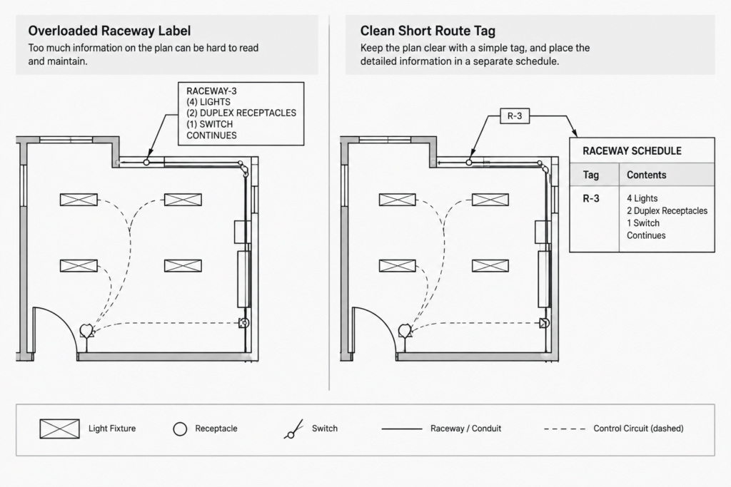
Develop a Tag Structure Before Drafting
Do not assign identifiers independently on each sheet. Establish a project-wide structure before tags are added in quantity. The structure can be simple, provided it is unique, readable, and compatible with the project’s schedules.
A tag may contain a route category and a sequential identifier, but its exact format should follow the project documentation standard. Avoid embedding information that is likely to change. For example, including a sheet number, room number, equipment location, or raceway description in every identifier can create unnecessary renaming when the design is revised.
Define the scope of one identifier
The team should decide what one tag represents. It might identify an entire source-to-destination pathway, one segment between pull points, or a grouped run shown diagrammatically. Mixing these interpretations causes duplicate records and unclear continuation references.
If a route changes condition, passes through an intermediate enclosure, or branches, determine whether the identifier continues or a new segment begins. Record that decision in the drafting procedure rather than leaving it to individual judgment on each sheet.
Reserve identifiers centrally
Maintain a controlled list of assigned tags. This may be a CAD table, spreadsheet, design database, or another approved project record. The important point is that multiple drafters should not create duplicate IDs in separate files.
Retired identifiers should normally remain traceable in the working record. Quietly reusing an old tag for a different route can make redlines, review comments, and earlier issue sets difficult to interpret.
Build a Practical CAD Tag Block
A raceway tag block should be visually simple and technically controlled. It usually needs an identifier field, a consistent text style, and a leader or attachment method appropriate for the plan. If a block uses attributes, use predictable attribute names so that extraction and checking tools can recognize them.
Useful block properties may include:
- an editable route identifier;
- an optional segment or continuation field;
- an optional reference to a schedule or note;
- a clear insertion point;
- ByLayer graphic properties where required by the CAD standard;
- and annotation behavior suited to the project’s plotting workflow.
Keep descriptive data in visible attributes only when readers need it on the plan. Hidden attributes can support data extraction, but they require disciplined maintenance because reviewers cannot confirm them from a plot.
Avoid exploding tag blocks to solve local graphic problems. Exploded tags lose their consistent attribute structure and become harder to audit. If one tag regularly needs a different orientation or leader arrangement, create a controlled variation that preserves the same data fields.
Place Tags Where the Route Is Unambiguous
Place a tag close enough to its raceway line that the association is obvious. On crowded plans, use a leader rather than positioning the label between several parallel routes. A tag should not appear to point at a wall, duct, cable tray, or architectural line by accident.
Long routes may need repeated labels for readability, especially when they pass through separate plan areas. Repeated labels should carry the same identifier and should not create additional schedule records. When a route branches, use branch identifiers or segment records according to the project convention rather than placing the parent tag on every branch without explanation.
Tagging grouped raceways
A single schematic line may represent multiple raceways, but the drawing must communicate that abstraction. A group tag can reference a schedule that lists the members, or individual tags can be placed where adequate space exists. Do not assume that line count alone explains the intended quantity or organization.
Tagging concealed and diagrammatic routes
Some plan routes communicate connectivity rather than exact installed alignment. Use notes, legends, or linetypes to distinguish diagrammatic routing from specifically coordinated routing. The presence of a precise-looking polyline should not imply verified field positioning when the drawing only establishes design intent.
Coordinate Continuations Between Sheets
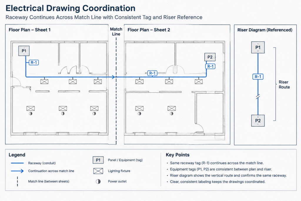
A route crossing a match line needs more than the same line appearing in another file. Place continuation references at both ends and verify that they point to the correct counterpart. The route identifier should remain consistent unless the documented scope changes at that boundary.
When plans use different orientations or scales, compare recognizable background features as well as coordinates. A continuation can be geometrically aligned yet still be incorrectly labeled. Review the route direction, source, destination, nearby equipment, and matching identifier together.
For routes that transition between a floor plan and a riser, single-line diagram, section, or detail, use the same equipment names and route IDs where those drawing types are intended to describe the same system. Do not force a physical route tag onto a conceptual diagram if the diagram uses a different documentation structure; instead, provide an explicit cross-reference.
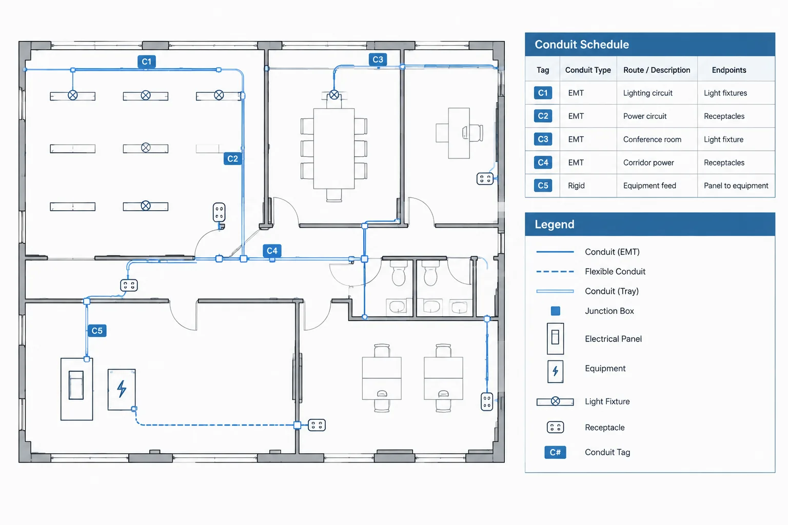
Create a Raceway Schedule That Supports Checking
The schedule should contain enough information to identify and coordinate each route without becoming a substitute for design calculations or specifications. Suitable columns depend on project scope, but commonly useful fields include:
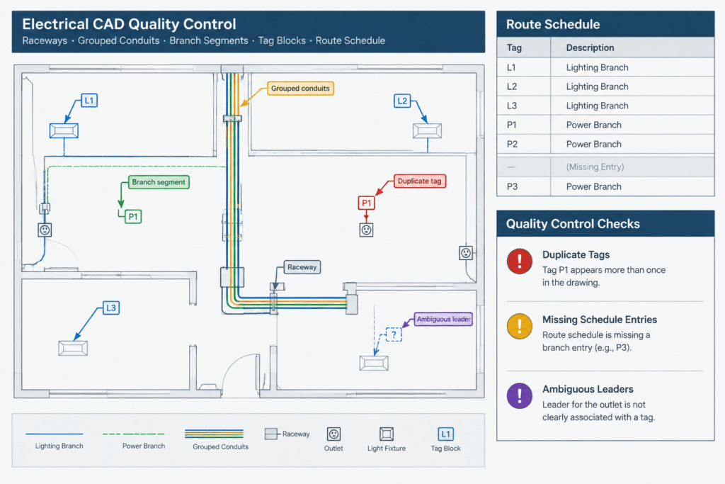
- route identifier;
- origin;
- destination;
- general service or system description;
- associated circuit, feeder, or cable reference;
- raceway description when required;
- related detail or note;
- and remarks or status.
Use equipment tags as origins and destinations when possible. Free-text descriptions such as “panel in electrical room” are difficult to coordinate if several rooms or panels are present. The equipment identifier should match the plan, diagram, and applicable schedule exactly.
Layer and Graphic Organization
Place raceway paths, tags, and continuation symbols on deliberate layers. Separating them can help with visibility control, plotting, and quality checks. For example, a drafter may need to inspect route geometry without annotation or isolate all tags to find duplicates.
Layer names and colors should follow the project’s CAD standard rather than a universal naming formula. More important than the exact name is consistent use. Tags placed on general text layers are easier to miss during route-specific audits.
Use linework hierarchy to distinguish raceways from architectural backgrounds and other electrical systems. Crossings should remain readable, and line gaps or masking should not accidentally imply a connection. Where routes overlap, a section or enlarged view may communicate the arrangement more clearly than increasingly complex plan graphics.
Quality-Control Checks Before Issue
A focused raceway-tag review can catch coordination problems that a general plot check may miss. Before issuing the drawings, verify the following:
- Every scheduled route appears on the relevant drawing.
- Every visible route tag has a corresponding record or defined note.
- No identifier is assigned to unrelated routes.
- Origins and destinations match equipment tags elsewhere in the set.
- Continuation references work in both directions.
- Repeated tags describe the same route rather than duplicate schedule entries.
- Branches and segment changes follow the documented convention.
- Tags remain legible and unambiguous at plotted scale.
- Demolished, future, alternate, and existing routes are graphically distinguished where applicable.
- Unused or retired route records are handled according to the project revision procedure.
Whenever possible, perform both a data review and a plotted review. Data checks can identify missing or duplicate attributes, while a plot reveals misplaced leaders, masked labels, and tags that appear to reference the wrong line.
A Maintainable Raceway Documentation Workflow
The most reliable workflow treats the route ID as shared project data rather than ordinary plan text. Define the identification rules, reserve tags centrally, place controlled CAD blocks, connect each tag to a schedule record, and verify references across every affected drawing type.
This approach makes revisions easier because the design team can trace a route from plan to schedule and from one sheet to another. It also helps prevent an attractive but incomplete drawing from being mistaken for coordinated documentation. CAD blocks supply the graphic vocabulary; consistent tagging gives those graphics a usable project-wide identity.
Using This Reference in a CAD Production Workflow
Raceway coordination is easier when the team agrees on the documentation method before route tags are placed throughout the drawing set. A practical starting point is to define what each identifier represents, which record controls its description, and how a route will be referenced when it leaves a view or changes drawing type.
Establish the documentation relationship
Each route graphic, visible tag, and schedule entry should have a clear relationship. The route line shows the pathway, the tag supplies its identity, and the schedule or associated note carries information that would be difficult to maintain as repeated plan text. Sections and details can then describe conditions that the plan cannot communicate clearly.
Review changes by route rather than by sheet
Sheet-by-sheet checking may overlook a mismatch that occurs at a continuation or between a plan and a schedule. When a route is revised, follow its identifier through every affected view and record. Confirm the origin, destination, branch treatment, equipment references, and continuation callouts as one coordinated documentation path.
Prepare tags for project handoff
Before files are archived or transferred, confirm that tag blocks remain intact, attribute values are usable, and obsolete identifiers have been handled according to the project revision procedure. The final plotted set should remain understandable without depending on hidden CAD data, while the working files should preserve enough structure for future checking and revision.
Common Documentation Warning Signs
- A raceway line ends at a match line without a continuation reference.
- A plan tag exists, but no corresponding schedule record or defining note can be found.
- The same identifier appears on routes with unrelated origins or destinations.
- Similar routes use inconsistent block types, attribute names, or text formatting.
- A schedule identifies equipment differently from the plan or diagram.
- Exploded tags or manually typed labels prevent reliable extraction and auditing.
- A route appears precisely located even though the drawing only intends to show diagrammatic connectivity.
These conditions do not automatically indicate a design error, but they should prompt a coordination review before the documents are issued.
Frequently Asked Questions
What is a raceway tag in an electrical CAD drawing?
A raceway tag is a controlled identifier associated with a conduit, duct, sleeve, or grouped pathway shown in the drawing. It connects the route graphic to a schedule, note, diagram, detail, or continuation reference.
Should a raceway tag contain the complete route description?
Usually, the tag should remain concise and direct the reader to the controlling record. Keeping longer descriptions in a schedule or keyed note reduces plan congestion and makes revisions easier to coordinate.
Can the same route tag appear more than once?
Yes. A long route may need repeated labels in separate plan areas, and the same identifier may appear in another coordinated drawing type. Repeated tags should refer to the same documented route rather than create duplicate records.
How should a raceway be tagged when it crosses onto another sheet?
Keep the route identifier consistent when the documented route remains the same, and provide reciprocal continuation references at the relevant boundaries. Both views should be checked for matching route direction, nearby equipment, and destination context.
Should route tags be ordinary text or attributed CAD blocks?
Controlled attributed blocks are generally easier to standardize, extract, and audit than independent text. The selected method should follow the project CAD standard and remain readable in the plotted deliverable.
How are grouped raceways documented?
The drawing should explicitly show whether one line and tag represent a group or an individual pathway. A group tag may refer to a schedule that identifies its members, while another project may require separate route records. The convention should remain consistent throughout the set.
What is the difference between a route tag and a continuation callout?
The route tag identifies the pathway. A continuation callout tells the reader where that pathway continues beyond the current view. They perform related but different documentation functions and may be used together.
Why should exploded raceway tag blocks be avoided?
Exploding a tag can remove its controlled attributes and break consistency with extraction or checking tools. A managed block variation is preferable when a different orientation, leader, or graphic arrangement is needed.




Leave a Reply
You must be logged in to post a comment.