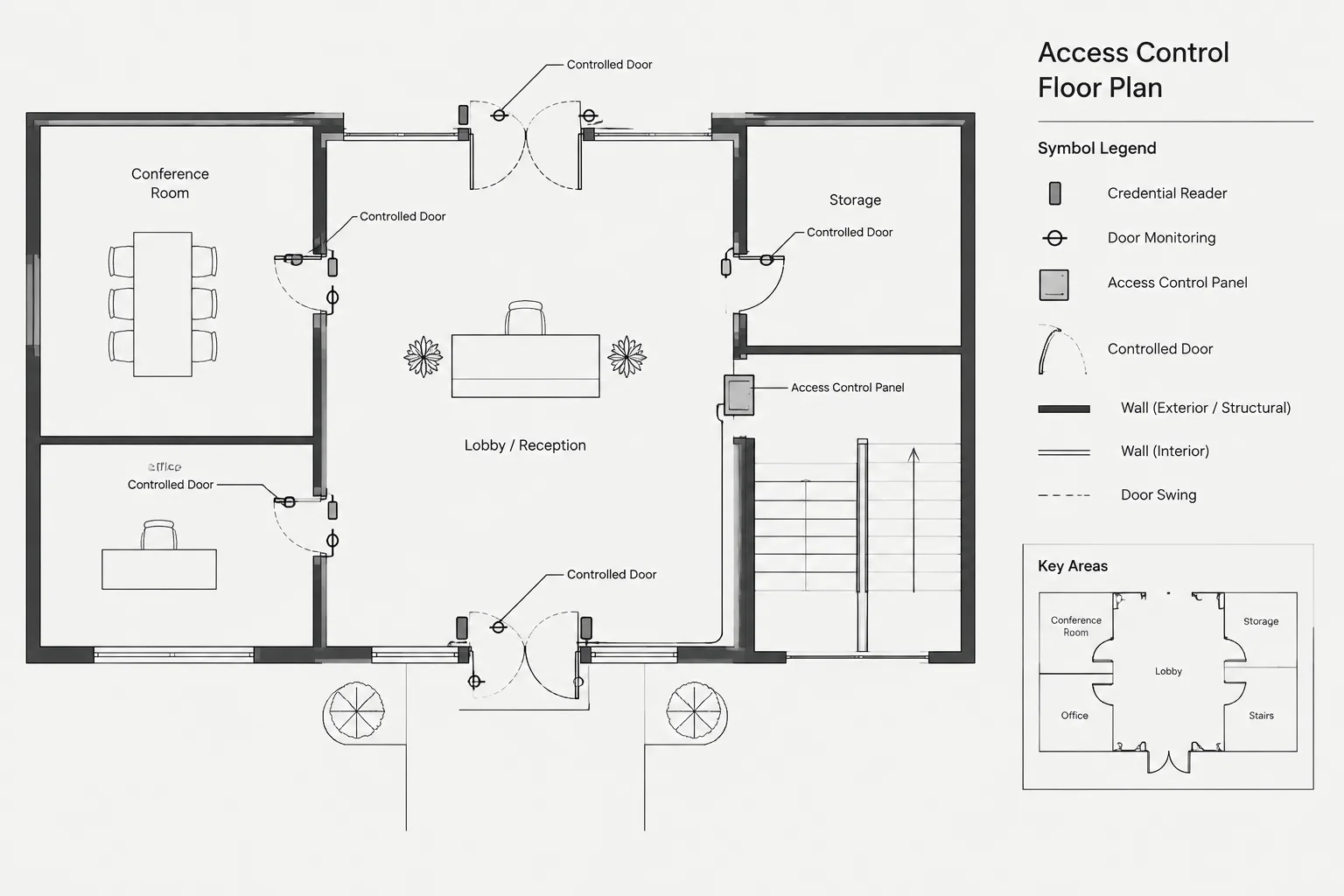
Drafting access control plans in CAD requires more than placing security symbols beside doors. The drawing must connect each controlled opening to its devices, identifiers, pathways, supporting equipment, schedules, and related disciplines. The guidance below explains how to organize that information so the plan remains readable while still communicating coordinated design intent.
An access control plan documents which openings are controlled, what devices are associated with each opening, and how those devices relate to security panels, power supplies, door hardware, and monitoring systems. Although it is usually drawn over an architectural floor plan, it should communicate more than device locations. A useful access control drawing also establishes door identity, functional relationships, wiring intent, and references to supporting schedules and diagrams.
The drafter’s role is to turn information from several disciplines into a coordinated drawing package. Architectural door numbers, hardware sets, electrical power requirements, security device selections, fire alarm interfaces, and owner operations may all affect the same controlled opening. The plan should make those relationships understandable without becoming a crowded wiring diagram.
Start with the door, not the individual device
A controlled door is best treated as a coordinated assembly. Depending on the project, that assembly may include a credential reader, electrified locking hardware, door position monitoring, request-to-exit detection, local power equipment, an intercom station, or other devices. Drawing each symbol independently without connecting it to a door identifier can make review difficult.
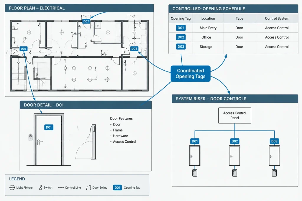
Begin by confirming the architectural door number and the direction of travel through the opening. Then assign the access control opening tag used throughout the security documents. In some projects, the access control tag matches the architectural door number. In others, it follows a separate security naming system. Whichever method is used, maintain a cross-reference so reviewers can move between the floor plan, door schedule, hardware information, and security documentation.
For pairs of doors, gates, turnstiles, and openings with multiple controlled leaves, clearly identify which leaf or passage is controlled. Do not assume that placing a reader symbol near an opening communicates the intended operation.
Build a practical symbol set
Access control symbols should remain visually distinct at the plotted scale while fitting into crowded areas around doors. Use a consistent symbol family for field devices and a separate graphic treatment for panels, power supplies, and other head-end equipment.
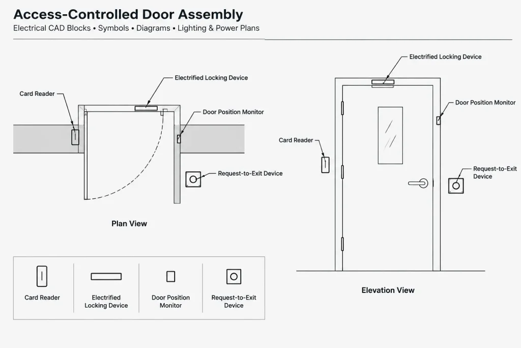
| Drawing item | What the symbol should communicate | Common coordination concern |
|---|---|---|
| Credential reader | Reader location and controlled side of the opening | Door handing, wall construction, and nearby switches or controls |
| Electrified locking device | Association with the controlled opening | Architectural hardware set and power source |
| Door position device | Monitoring point assigned to the door | Integration with door hardware or frame preparation |
| Request-to-exit device | Exit-side detection or release function | Device type, coverage, and coordination with other ceiling or wall devices |
| Access control panel | Panel identity and general location | Space, pathways, power, network, and environmental requirements |
| Power supply or interface enclosure | Supporting equipment associated with controlled openings | Mounting location and connection responsibility |
| Intercom or entry station | Communication point at an entrance | Accessibility, camera coverage, and release interface |
Generic CAD blocks are useful starting points, but their appearance does not establish project suitability. Verify every symbol against the project legend and device list. Avoid relying on a manufacturer’s product silhouette when a simple, legible symbol can convey the drawing function more clearly.
Use tags to carry information that graphics cannot
A compact device tag can connect a plan symbol to schedules, details, panel assignments, and cable information. Tags may identify an opening, device type, panel, point, or detail reference. The exact format should match the project’s documentation method.
Keep the plan tag concise. Long descriptions placed beside every device quickly obscure door swings, walls, and adjacent equipment. Store repetitive information in a schedule or block attributes when appropriate, and use the visible tag as the link to that information.
Attributes can improve consistency when access control symbols are reused across many sheets. Useful fields may include device identifier, opening identifier, panel assignment, remarks, and status. Attribute values should be checked before issue; a smart block with outdated data is more misleading than a simple graphic.
Separate location plans from connection diagrams
The floor plan should emphasize physical location and opening association. It does not need to show every conductor between every component. Dense wiring lines around doors can hide architectural information and create ambiguous crossings.
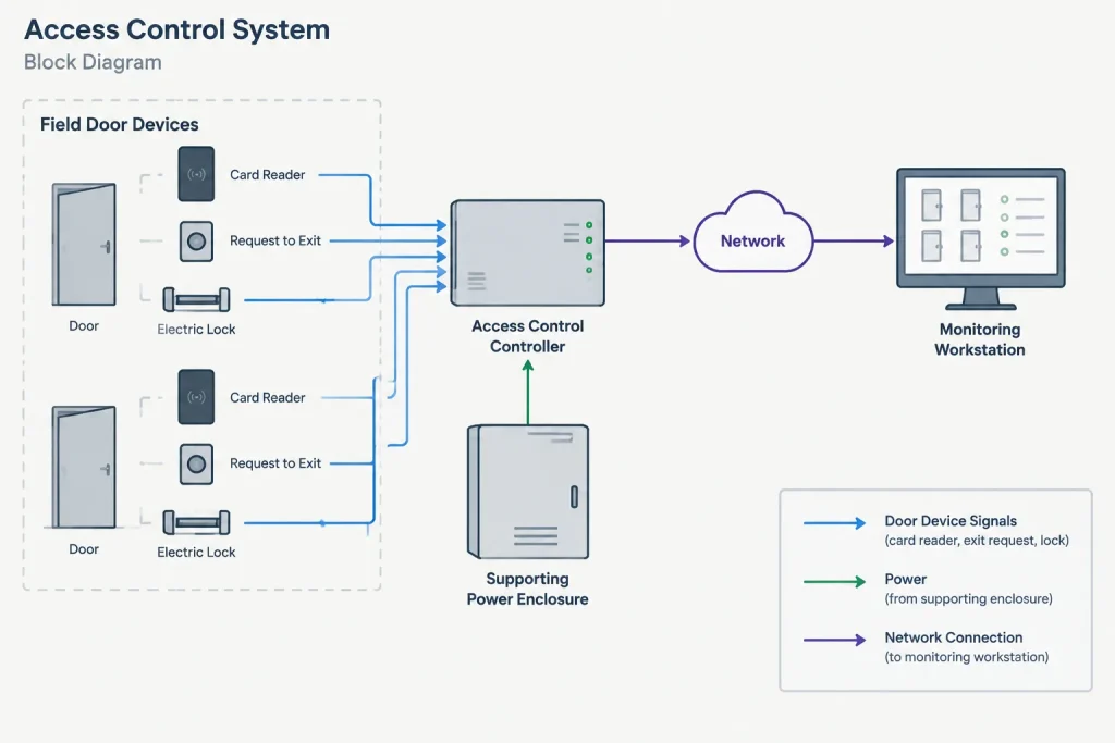
Use supporting diagrams for system relationships:
- Floor plans show controlled openings, field devices, panel locations, and pathway intent.
- Door details or elevations clarify device placement and relationships within a specific opening assembly.
- Riser or block diagrams show the relationship among field devices, controllers, power equipment, networks, and monitoring systems.
- Point-to-point diagrams document detailed terminal or connection intent when required by the project scope.
- Schedules organize opening functions, device assignments, panel references, and coordination remarks.
Cross-reference these documents directly. A controlled opening shown on a plan should not require reviewers to guess which diagram or schedule entry applies.
Draft pathway intent without creating false precision
Access control plans may show security cable routes, conduit pathways, cable tray connections, home runs, or general routing zones. The selected level of detail should reflect the purpose of the document. A design drawing may indicate routing intent, while a coordinated installation drawing may need a more developed pathway layout.
Use distinct layers or linetypes for device symbols, pathways, home runs, panel equipment, text, and references. If a pathway continues beyond the visible area, add a continuation note or destination tag rather than ending the line without explanation. Where several devices at one door share a route, a grouped home-run notation may be clearer than overlapping parallel lines.
Do not draw a highly specific concealed route unless it has been coordinated with the building background and other trades. An apparently precise line may be interpreted as an approved route even when it was placed only for diagrammatic clarity.
Coordinate with adjacent disciplines
Access control documentation sits at the boundary of several drawing packages. A disciplined coordination review should address at least the following relationships:
- Architecture: door numbers, handing, frames, wall types, glazing, vestibules, and door schedule changes.
- Door hardware: locking functions, monitoring devices, exit hardware, operators, and hardware-set references.
- Electrical: power sources, supporting enclosures, panel locations, and pathway responsibilities.
- Fire alarm and life safety documentation: required release or monitoring interfaces as determined by the project design team.
- Information technology: network connections, equipment-room coordination, and communications pathways.
- Other security systems: cameras, intrusion monitoring, intercoms, visitor entry, and security management interfaces.
The CAD drawing should record agreed design intent rather than resolve operational or code questions by assumption. Items affecting egress, emergency release, accessibility, or life safety require review by the responsible project professionals.
Organize layers for controlled visibility
A practical layer structure allows access control information to be reviewed independently and combined with other low-voltage systems when needed. Separate layers may be useful for symbols, device tags, cable or pathway graphics, equipment, coverage or coordination zones, and detail references.
Avoid placing all security content on one layer. Reviewers may need to display access control devices while hiding routes, or show panel locations without showing every annotation. Likewise, do not place security symbols on architectural background layers, because background updates may replace or alter them.
If the drawing contains sensitive operational information, follow the project’s document-control requirements. Layer freezing is a drafting convenience, not a security control. Restricted information should be managed through the approved issue and file-sharing process.
Create an opening schedule that matches the plan
An access-controlled opening schedule can serve as the central coordination record. Its columns should be selected according to project needs rather than copied from an unrelated template. Typical categories include opening identifier, architectural door number, controlled direction, reader type, locking function reference, monitoring points, request-to-exit function, panel assignment, diagram reference, and remarks.
The schedule and plan should use the same identifiers. If a door changes number or is removed from the architectural background, update the corresponding plan tags, schedule rows, diagrams, and panel information together. A mismatch between these documents can be difficult to detect during installation review.
Perform a controlled-opening quality check
Before issuing the drawings, review each controlled opening as a complete unit rather than checking symbols by type. For every opening, verify that:
- The door or opening identifier matches the current architectural background.
- The controlled side and intended direction are understandable.
- Associated devices are visually connected to the correct opening.
- Tags match the schedule, diagram, and panel references.
- Door hardware and electrical coordination items are identified.
- Pathways have clear origins, destinations, or continuation references.
- Symbols remain legible at the intended plot scale.
- Demolition, existing, future, and new work statuses are not mixed.
- Unresolved interfaces are marked for coordination rather than silently assumed.
A clear access control plan is not simply a collection of reader symbols. It is an organized record of controlled openings, device relationships, supporting equipment, and interdisciplinary design intent. Treating each opening as a coordinated assembly produces drawings that are easier to review, schedule, revise, and connect to the rest of the electrical and security documentation.
Manage revisions across the complete drawing set
An architectural background change can affect more than the visible position of a door. A revised opening may also change its identifier, handing, controlled side, hardware relationship, nearby device locations, pathway routing, and schedule entry. Review background updates by controlled opening rather than treating them as graphic reference changes only.
When an opening is added, removed, relocated, or renamed, trace its identifier through the plan, device attributes, opening schedule, diagrams, panel references, and coordination notes. Unresolved differences should be marked for review instead of being hidden by copying information from an earlier issue.
Keep block behavior consistent
Access control blocks should have predictable insertion points, orientation, attribute placement, and layer assignments. A symbol that is mirrored or rotated may still look correct while implying the wrong controlled side or device relationship. Review the tag and functional meaning after changing block orientation.
Avoid maintaining visually identical blocks with conflicting attribute definitions. A controlled block library makes global updates easier and reduces the risk that similar symbols carry different data structures.
Check the published package, not only the working file
Before issue, review the plotted or exported sheets with the same layer visibility, references, and plot settings intended for delivery. Confirm that screened architectural backgrounds remain readable, security symbols are distinguishable, tags do not mask door information, and external references are current.
The plan, schedule, legend, and supporting diagrams should represent the same revision state. A correct working drawing can still produce an unreliable package if referenced files, schedule exports, or plotted sheets were generated at different stages of coordination.
Frequently asked questions about access control CAD plans
Should every access control device appear on the floor plan?
The plan should show the devices needed to communicate location and opening association. Detailed terminals, internal connections, and other connection information may be clearer in supporting diagrams or details.
Can a reader symbol alone identify the controlled side of a door?
Not reliably. Symbol placement can become ambiguous near vestibules, door pairs, or crowded walls. Use consistent placement, opening tags, directional graphics, or notes that match the project legend.
Should access control pathways be drawn as exact installed routes?
Only when the documentation scope and coordination support that level of precision. Otherwise, show routing intent clearly without implying that an uncoordinated concealed path has been approved.
What information belongs in block attributes?
Attributes are useful for identifiers, opening associations, panel assignments, references, status, and remarks. Visible plan text should remain concise, while schedules can carry information that would overcrowd the plan.
How should existing and new access control devices be distinguished?
Use the project’s established graphic and layer conventions for work status. Apply those conventions consistently to symbols, tags, pathways, schedules, and diagrams so different conditions are not confused.
Does an access control CAD block define the required product or operation?
No. A block represents drawing intent according to the legend. Product selection, door operation, hardware functions, interfaces, and life-safety requirements must be confirmed through the coordinated project documentation and responsible design professionals.












Leave a Reply
You must be logged in to post a comment.