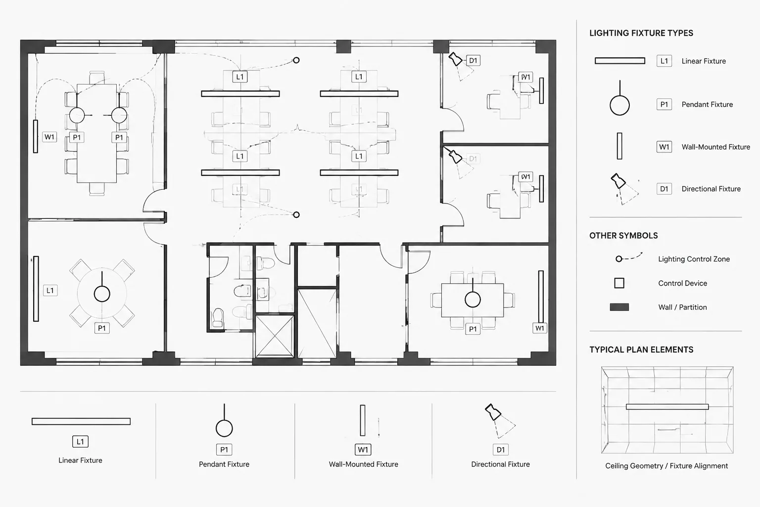
Lighting fixture orientation in CAD can represent equipment direction, architectural alignment, or graphic organization. Because those meanings are not interchangeable, a well-drafted lighting plan should make clear what rotates, what remains readable, and how each symbol corresponds with the legend and fixture schedule.
This reference explains how to manage those relationships without allowing block edits, copied attributes, mirrored geometry, or background revisions to introduce misleading plan information.
Lighting symbols are often treated as simple plan markers, but their orientation can carry important design and coordination information. A rotated linear fixture may indicate its intended alignment with a corridor. A directional luminaire may need to face a wall, display, aisle, or exterior area. Even a visually symmetrical symbol can include text, an emergency indicator, or a control reference that should remain readable.
Managing lighting fixture orientation in CAD therefore requires more than rotating blocks until the plan looks balanced. The drafting workflow should distinguish between physical orientation, symbol orientation, annotation orientation, and alignment with the architectural background. It should also preserve consistent fixture identification across plans, schedules, legends, and details.
What Fixture Orientation Can Communicate
Orientation has different meanings depending on the fixture and drawing type. For some luminaires, rotation represents the actual direction of the equipment. For others, it is primarily a graphic decision used to improve plan readability.
- Linear fixtures: Rotation commonly indicates the long-axis alignment of the fixture.
- Directional fixtures: The symbol may show the intended aiming or light-output direction.
- Wall-mounted fixtures: Orientation can identify the supporting wall or mounting face.
- Asymmetrical fixtures: The symbol may distinguish a forward, rear, left, or right side.
- Symmetrical fixtures: Rotation may have no physical meaning, although associated text still needs consistent orientation.
- Decorative fixtures: Orientation may be coordinated with architectural geometry, furniture, or a reflected ceiling pattern.
The legend should make directional meaning apparent when it cannot be understood from the symbol alone. A drafter should not assume every rotated fixture symbol communicates aiming intent.
Separate Geometry from Annotation
A common CAD problem occurs when fixture geometry and annotation are contained in a single rigid block. Rotating the fixture also rotates the type mark, circuit information, control-zone tag, or emergency notation. The resulting text may become upside down, conflict with adjacent symbols, or appear inconsistent across the sheet.
A more flexible symbol strategy separates information according to how it should behave:
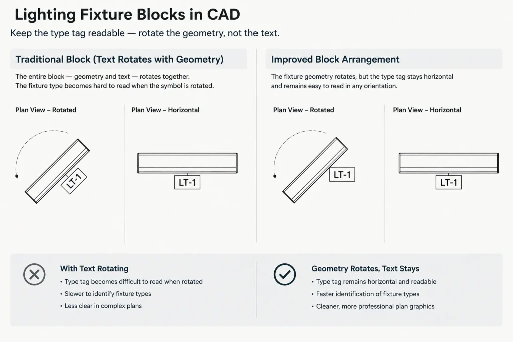
- Fixture geometry may rotate to match the intended physical orientation.
- Fixture type marks should normally remain readable from the drawing’s established viewing direction.
- Circuit and control annotations may be separate text, attributes, or tags positioned for local clarity.
- Directional arrows or aiming indicators should rotate with the part of the symbol whose direction they describe.
- Emergency or special-status graphics should remain visually associated with the correct fixture after rotation or mirroring.
Before modifying a library block, determine whether the project requires a rotating symbol, a fixed annotation, or both. Exploding blocks simply to correct text orientation can create uncontrolled variations and make later updates more difficult.
Coordinate with the Ceiling Background
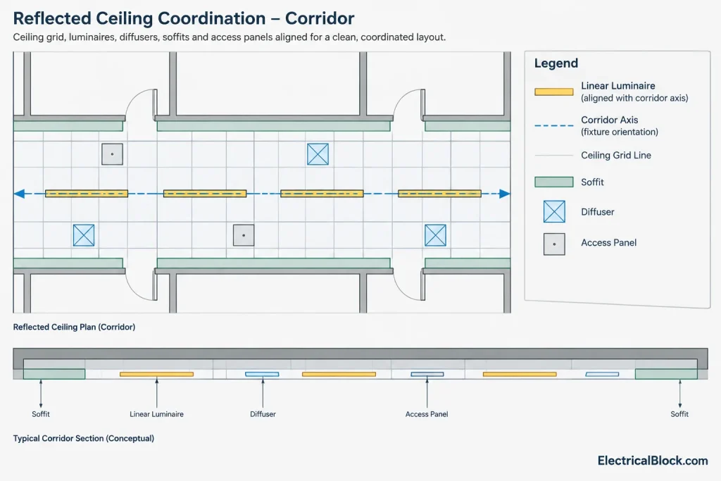
Lighting plans are frequently developed over architectural reflected ceiling information. The electrical drawing may show fixture symbols, while the architectural background establishes ceiling grids, soffits, ceiling types, room boundaries, and feature alignments.
Use the background as a coordination reference rather than as an automatic placement rule. Architectural geometry may change between drawing issues, and imported ceiling linework may contain minor drafting inconsistencies. Fixture placement should follow the current design intent and the project’s agreed coordination process.
Useful alignment relationships
- Linear fixtures aligned with corridors, ceiling elements, or architectural axes.
- Repeated fixtures arranged consistently within a room or open area.
- Wall-mounted luminaires oriented toward the correct mounting surface.
- Pendants coordinated with tables, counters, displays, or other referenced elements.
- Directional fixtures shown with a clear relationship to the intended target area.
- Fixtures near ceiling transitions checked against soffits, clouds, beams, and access elements.
Object snaps and construction lines can help establish alignment, but temporary drafting geometry should be placed on a controlled layer and removed or hidden before issue. Avoid forcing fixtures onto ceiling intersections when the background does not reflect the approved design location.
Establish a Repeatable Rotation Workflow
A consistent placement method reduces random symbol angles and makes later review easier. The following workflow is suitable for drafting and documentation coordination:
- Identify the fixture type. Confirm that the symbol matches the current legend and schedule designation.
- Determine whether direction matters. Decide whether rotation represents physical equipment orientation, lighting direction, or only graphic alignment.
- Select a reliable reference. Use a wall, ceiling grid, centerline, room axis, or other controlled project geometry.
- Place and rotate the fixture geometry. Maintain consistent insertion behavior for repeated symbols.
- Correct annotation readability. Reposition or reorient type marks, circuit tags, and control references without changing their meaning.
- Check nearby coordination items. Review diffusers, sprinklers, detectors, access panels, structural elements, and other visible background information as applicable to the drawing.
- Compare repeated spaces. Verify that similar rooms use a consistent orientation unless an intentional exception is documented.
- Review the plotted output. Confirm that symbol direction and annotations remain legible at the sheet’s intended presentation scale.
Rotation, Mirroring, and Symbol Meaning
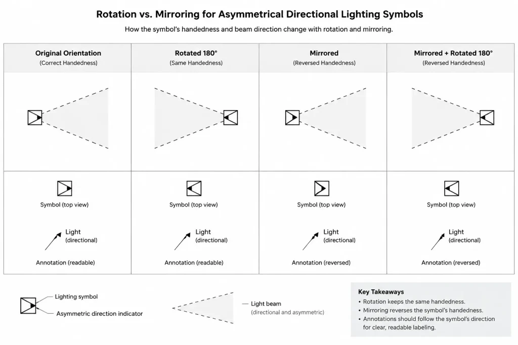
Rotation and mirroring are not interchangeable. Rotation turns geometry around an insertion point, while mirroring reverses its handedness. For a symmetrical fixture, that difference may not be visible. For an asymmetrical or directional symbol, mirroring can change the apparent meaning.
Use particular care with symbols that include arrows, shielding indicators, wall references, integral controls, or offset mounting features. A mirrored block may also reverse embedded text or produce a library variation that no longer matches the legend.
| Drafting operation | Primary risk | Recommended check |
|---|---|---|
| Rotate | Unreadable tags or inconsistent angles | Check text orientation and alignment reference |
| Mirror | Reversed directional or handed meaning | Compare the result with the legend and fixture definition |
| Copy | Carrying the wrong circuit, zone, or status data | Review associated attributes and annotations |
| Replace block | Losing the original rotation or tag relationship | Verify insertion point, orientation, and identifying data |
Keep Plans, Legends, and Schedules Consistent
The fixture schedule generally identifies the luminaire type, while the plan shows its location and orientation. These documents should complement one another without assigning conflicting meanings to the same symbol.
If the plan symbol includes a directional feature, show that feature consistently in the legend or explain it with a drawing note. If different orientations represent different fixture configurations, they may require distinct type designations rather than casual rotation of one generic symbol. That decision should come from verified project information, not from graphic preference alone.
Schedule coordination should also include special fixture status. Normal, backup-powered, switched, dimmed, controlled, or otherwise differentiated fixtures may use tags, linework, fills, or supplemental notation. Rotation must not detach that status information from the corresponding fixture.
Common Drafting Problems
Fixture geometry follows the room, but the tag follows the block
This produces sideways or inverted type marks. Separate the tag behavior from the rotating geometry or provide a controlled way to maintain readable annotation.
Similar rooms use slightly different angles
Small angular differences are visually distracting and may suggest a design distinction that does not exist. Use common references and copy aligned groups where appropriate.
Mirrored symbols no longer match the legend
Review whether mirroring changed a directional arrow, wall side, or asymmetrical feature. Replace the symbol with a verified orientation if necessary.
Fixture orientation conflicts with updated ceiling geometry
When the architectural background changes, previously aligned fixtures may appear offset or incorrectly rotated. Overlay review should include both location and angle, not location alone.
Directional meaning is visible only in CAD
Color, layer names, or object properties may communicate information to the drafter but disappear in a monochrome plot. Confirm that the published drawing communicates direction through visible graphics and notation.
Quality-Control Review Before Issue
A focused orientation review can be performed separately from a general lighting-plan check. Isolate or visually emphasize fixture layers, then scan the drawing by room, corridor, or ceiling area.
- Confirm that each directional symbol faces the intended reference or target.
- Check linear fixture alignment within repeated rows and architectural features.
- Look for accidentally mirrored blocks.
- Verify that fixture tags remain readable and attached to the correct symbols.
- Compare plan symbols with the legend and fixture schedule.
- Review repeated rooms for intentional and unintentional differences.
- Check that emergency or other special-status notation remains associated after rotation.
- Inspect the plotted sheet rather than relying only on model-space appearance.
Lighting fixture orientation in CAD is a small drafting detail with broad coordination consequences. Treating geometry, direction, and annotation as separate but related information produces plans that are easier to review, coordinate, revise, and interpret.
Manage Orientation as Drawing Data
Orientation should be treated as part of the documented fixture instance rather than as a purely visual adjustment. A reviewer should be able to identify the fixture type, understand whether its direction matters, and trace its annotations without inspecting hidden CAD properties.
This distinction is especially important when blocks are copied between rooms or replaced during design development. The symbol may retain its angle while losing an associated tag, or it may inherit annotation from the source fixture even though the new location has different project data.
Use a clear information hierarchy
- Fixture identity: The type mark should connect the plan symbol to the applicable legend or schedule entry.
- Physical direction: Aiming, mounting-face, or asymmetrical information should be visible where direction affects interpretation.
- Graphic alignment: Symbols arranged for drawing clarity should not imply a physical distinction unless that meaning is documented.
- Associated status: Control, circuit, emergency, or other project notation should remain connected to the correct fixture instance.
- Revision state: Updated backgrounds and replaced blocks should trigger a review of both fixture location and orientation.
Preserve Intent During File Handoffs
Orientation logic can become unclear when another drafter receives a file without knowing how the block was constructed. Consistent insertion points, controlled attributes, recognizable layer assignments, and visible legend information make the drawing easier to maintain.
If a symbol depends on special rotation behavior, document that behavior through the project drafting system rather than relying on individual memory. The published sheet should still communicate the essential result even when custom block controls, colors, or object properties are not visible.
Revision-review questions
- Did a background update change the architectural reference used for alignment?
- Did block replacement preserve the original orientation and identifying information?
- Do copied fixtures still carry the correct local annotations?
- Can directional meaning be understood in the plotted drawing?
- Do intentional exceptions appear deliberate rather than accidental?
These checks help separate a harmless graphic variation from a change that affects design communication. Any unresolved discrepancy should be coordinated through the project team rather than corrected by assumption.
Frequently Asked Questions
Should every lighting symbol be aligned in the same direction?
No. The appropriate orientation depends on the fixture, the architectural reference, and the meaning assigned to the symbol. Repeated fixtures should appear consistent where the design intent is consistent, but directional or wall-mounted fixtures may require different orientations.
Should fixture text rotate with the block?
Only when that behavior remains readable and follows the drawing’s annotation convention. Fixture geometry and identifying text often need separate controls so the equipment direction can change without producing inverted or sideways tags.
Is mirroring a lighting fixture block the same as rotating it?
No. Mirroring reverses handed geometry, while rotation changes its angle without reversing it. A mirrored directional or asymmetrical symbol may communicate a different condition and should be checked against the fixture definition and legend.
How should directional intent be shown?
Use visible symbol geometry, an aiming indicator, a plan note, or a clear legend convention as appropriate to the drawing. Do not rely only on color, layer names, or properties that may disappear from the issued sheet.
What should be reviewed after a ceiling background changes?
Review fixture position, angle, spacing relationships, tags, and nearby ceiling elements. A fixture can remain in the same location while becoming misaligned with revised architectural geometry.
Can fixture blocks be exploded to correct annotation?
Exploding may allow a quick visual adjustment, but it can also break consistent block behavior and complicate later revisions. A controlled symbol or annotation method is generally easier to coordinate and audit.












Leave a Reply
You must be logged in to post a comment.