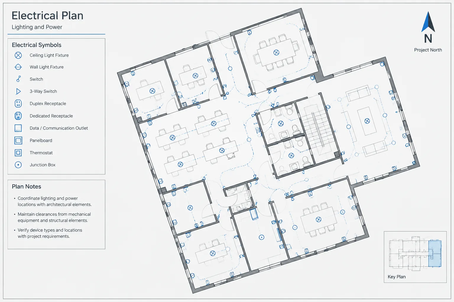
Electrical CAD plan orientation affects far more than the direction of a north arrow. It influences background coordination, symbol rotation, annotation readability, detail references, and the way reviewers compare related sheets.
This reference explains how to separate coordinated model geometry from sheet presentation while preserving clear directional meaning across plans, enlarged views, sections, elevations, and diagrammatic drawings.
Electrical plans often inherit their orientation from architectural, civil, structural, or survey backgrounds. That seems straightforward until a project includes rotated buildings, multiple wings, enlarged rooms, site plans, or sheets arranged differently for efficient use of space. If orientation is not managed deliberately, the same electrical equipment can appear to be on different sides of a room from one drawing to another.
A reliable electrical CAD plan orientation workflow does more than place a north arrow. It establishes how model geometry, sheet views, directional notes, symbols, and cross-references relate to the physical project. The objective is to let a reader move between plans, diagrams, details, and other disciplines without mentally reorienting the building each time.
Start by Distinguishing Project Orientation Terms
Drawing teams may use several forms of orientation. These terms should not be treated as interchangeable unless the project documentation defines them that way.
- True north indicates the geographic north direction represented by the project base information.
- Project north is a simplified working orientation adopted for plans and coordination. It may align a building wing horizontally or vertically on the sheet.
- Plan north describes the upward direction of a particular plan view. It may match project north, but a rotated viewport can make it different.
- Local orientation applies to an enlarged room, equipment area, or building wing that has been rotated for clarity.
The electrical drawings should follow the orientation strategy established for the coordinated drawing set. Drafters should not create an independent electrical north direction simply because it produces a more convenient layout.
Keep the Shared Model Geometry Stable
When disciplines exchange CAD backgrounds, the underlying model geometry should normally retain its coordinated location and rotation. Rotating an architectural external reference solely to make one electrical sheet easier to compose can introduce alignment problems, especially when updated backgrounds are received later.
A safer drawing structure is to keep coordinated geometry stable in model space and control sheet presentation through views or viewports. This separates two important concepts:

- Model orientation: Where the building and electrical information exist in the shared coordinate environment.
- Sheet orientation: How a selected area is presented to the reader on a plotted sheet.
If project requirements call for a different method, document that method clearly and use it consistently. The important point is to avoid unexplained rotations, copied backgrounds, and manually relocated geometry that no longer matches the coordination base.
Place North Arrows Where They Have Meaning
A north arrow should identify the orientation of the plan view in which it appears. Placing one generic arrow in a title block can be misleading when a sheet contains multiple viewports with different rotations.
For a sheet with one primary plan, the arrow may be located near the plan title or another visually stable part of the view. For multiple rotated plans, each plan should have enough orientation information to remove ambiguity. This may require a north arrow within each applicable view rather than a single sheet-wide symbol.
Build the North Arrow as a Controlled CAD Block
A practical north-arrow block can include separate graphic and text components while maintaining a predictable insertion point. Useful controls include:
- A clear arrowhead and directional shaft that remain legible at the plotted scale.
- An attribute or nearby label distinguishing true north from project north when both are shown.
- A defined rotation convention that the CAD team understands.
- Layer assignment appropriate for shared orientation graphics or electrical annotations.
- A block name that prevents it from being confused with section arrows, home-run arrows, or directional equipment symbols.
Do not assume that a north-arrow block downloaded from a library is already aligned with the project. Its internal zero rotation, text behavior, layer assignments, and plotting appearance should be checked before use.
Manage Rotated Viewports Without Rotating Annotation Incorrectly
Rotated views are useful for fitting angled wings or long buildings onto sheets. They also create common annotation errors. Device symbols may rotate with the model when they should retain a readable sheet orientation, while directional equipment symbols may remain upright when they should indicate a physical direction.
Classify drawing elements according to what their rotation communicates:

| Drawing element | Preferred rotation basis | Reason |
|---|---|---|
| Room-based electrical devices | Building or wall orientation | Placement should remain coordinated with the physical room layout. |
| Text and general notes | Sheet readability | Readers should not need to rotate the sheet to read routine annotations. |
| Directional luminaires or sensors | Design intent | Rotation may communicate aiming, coverage, or orientation. |
| Panel and equipment outlines | Physical installation orientation | The plan symbol should correspond to the equipment footprint or mounting surface. |
| North arrows | Plan-view orientation | The arrow must represent north relative to the displayed view. |
| Section and elevation markers | Referenced viewing direction | The marker direction identifies where the referenced view is looking. |
This classification prevents a global rotate command from changing information that should remain view-dependent. It also helps determine whether an annotation belongs in model space, paper space, or an annotation system managed by the project’s CAD platform.
Coordinate Directional Notes with the Drawing
Notes such as “east wall,” “north side,” or “route to west electrical room” can become unreliable when plans are rotated or when project north differs from true north. Where possible, use references that are stable across disciplines, such as room names, grid lines, equipment tags, column lines, or drawing references.
If cardinal directions are necessary, confirm which north convention governs the note. A detail labeled “north wall” should mean the same thing to the electrical, architectural, and structural teams. For a local enlarged view, consider identifying the corresponding wall or grid reference rather than relying only on the top, bottom, left, or right side of the sheet.
Handle Enlarged Plans and Details Carefully
An electrical room enlargement may be rotated to provide more space for equipment tags, dimensions, working-area graphics, or conduit routing. The enlargement should still connect clearly to its parent plan.
Include enough of the following information to make that relationship obvious:
- A callout on the parent plan identifying the enlarged area.
- A matching detail or view reference.
- Consistent equipment tags in both views.
- Grid lines, room names, or recognizable wall geometry.
- An orientation symbol when the enlargement is rotated.
- A plan title that identifies the level and area shown.
Avoid duplicating editable electrical geometry in both the overall plan and the enlargement unless the project has a defined method for controlling it. Duplicate symbols can drift apart during revisions, leaving different circuit, equipment, or status information in each view.

Check Orientation Across Related Electrical Drawings
Floor plans are not the only drawings affected by orientation. Site plans, roof plans, underground routing plans, equipment layouts, and reflected ceiling coordination views may use different bases or presentation angles.
Single-line diagrams and risers are generally diagrammatic rather than geographic. Their left, right, up, and down directions do not necessarily correspond to compass directions. This distinction should remain clear when a plan reference points to diagrammatic content. A feeder shown above another feeder on a one-line is not automatically located north of it in the building.
Sections and elevations require another check: the viewing direction must agree with the marker on the plan. When a plan viewport is rotated, verify that section arrows, elevation arrows, and their referenced titles still describe the intended view.
Use an Orientation Review Checklist
Before issuing an electrical drawing set, review orientation as part of CAD quality control:
- Confirm that electrical backgrounds align with the current coordinated base files.
- Verify that model geometry has not been unintentionally moved or rotated.
- Check every north arrow against the actual view orientation.
- Identify sheets containing multiple view rotations and provide orientation information where needed.
- Confirm that text remains readable in the intended plotting direction.
- Review directional device symbols separately from non-directional symbols.
- Check section and elevation markers after viewport changes.
- Compare enlarged plans with their parent plans.
- Search notes for cardinal-direction language that may be ambiguous.
- Confirm that plan references do not imply geographic meaning for diagrammatic drawings.
Create a Project Rule Before Drafting Expands
Orientation problems are easiest to prevent at the beginning of a project. The electrical CAD setup notes should identify the coordinated base orientation, the meaning of project north, how rotated views are handled, and where view-dependent annotations belong.
This does not require a lengthy manual. A concise, documented rule gives drafters a common basis for placing symbols and composing sheets. When orientation is treated as part of drawing coordination rather than as a decorative north-arrow task, electrical plans become easier to compare, update, and review.
A Practical Framework for Orientation Decisions
When an orientation question arises, first identify what the drawing element is intended to communicate. Most decisions relate to one of the following reference frames:
- Project reference: The coordinated location and orientation shared with architectural, structural, civil, or survey information.
- Displayed view: The way a plan or enlarged area is rotated and positioned on a sheet.
- Physical direction: The actual facing, aiming, mounting, or routing direction represented by an electrical symbol.
- Reading direction: The orientation that keeps notes, tags, and titles legible to the sheet reader.
These reference frames may agree on a simple plan, but they can diverge when a building wing or enlarged room is rotated. Treating them separately helps prevent a view adjustment from changing physical design intent or making annotation difficult to read.
Resolve Conflicts by Preserving Meaning
A symbol should not be rotated merely because nearby text was rotated, and text should not follow a symbol when doing so makes the sheet harder to read. Determine whether the rotation represents a real condition, a view presentation choice, or an annotation preference. Then apply the project drafting rule consistently.
When an exception is necessary, make it reviewable. A recognizable view title, orientation marker, grid reference, room name, or matching callout can explain the relationship without relying on the reader to infer it from page position.
Include Orientation in Revision Checks
Orientation should be reviewed whenever backgrounds, viewport rotations, plan extents, or enlarged views change. A revision can leave the electrical geometry correctly coordinated while making an old north arrow, section marker, or directional note inaccurate. Checking both geometry and presentation helps identify this type of documentation error before issue.
Frequently Asked Questions
Can a north arrow be placed only in the title block?
A title-block north arrow may be understandable when the sheet contains one consistently oriented plan. It can become ambiguous when separate viewports use different rotations. Each applicable view should provide enough information for its orientation to be understood.
Does rotating a viewport rotate the electrical model?
A properly managed viewport changes how coordinated geometry is displayed on the sheet without relocating the source geometry. Care is still required because annotations, north arrows, and directional symbols may need separate handling.
Should the electrical discipline establish its own project north?
Electrical drawings should normally follow the orientation strategy used by the coordinated project set. Creating an unrelated electrical convention can make backgrounds, references, and interdisciplinary reviews difficult to reconcile.
How should a rotated electrical room enlargement be identified?
Connect it to the parent plan with consistent callouts, view references, equipment tags, room information, grids, or recognizable wall geometry. Add an orientation symbol when the rotation would otherwise be unclear.
Are single-line diagrams and risers oriented geographically?
Not generally. They are diagrammatic representations, so their page directions do not automatically correspond to compass directions or physical equipment positions. Plan references should not imply a geographic relationship unless the documentation explicitly establishes one.
Why can a directional symbol remain rotated while its label stays upright?
The symbol rotation may represent physical aiming, facing, or installation orientation, while the label serves the reader. Separating these purposes preserves both design meaning and sheet readability.












Leave a Reply
You must be logged in to post a comment.