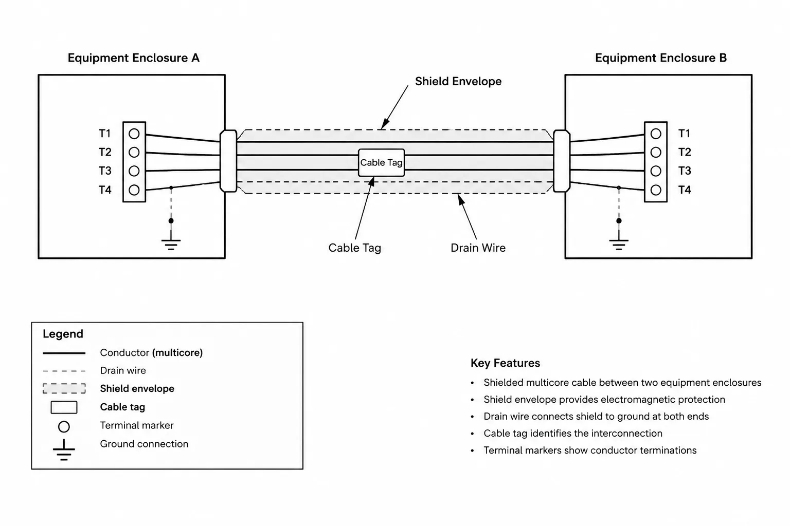
Effective cable shield documentation connects graphical conventions with cable identification, endpoint conditions, terminal references, and schedule data. When those elements are coordinated, a reader can distinguish the shield from the drain wire and trace the documented arrangement without relying on assumptions.
The guidance below explains how to organize this information across schematics, interconnection diagrams, terminal drawings, and cable schedules. It addresses drawing clarity and quality control only; the required cable construction and termination method remain project-specific design decisions.
Shielded cables appear in control, instrumentation, communications, audio, security, and other systems where unwanted electrical noise may affect a signal. On drawings, however, simply labeling a cable as “shielded” is rarely enough. The documentation should also communicate which conductors belong to the cable, how the shield is represented, where the shield or drain wire terminates, and how that information relates to cable schedules and terminal drawings.
This guide focuses on cable shield documentation in CAD rather than physical installation. Actual cable selection and termination arrangements must be verified against the project design, equipment requirements, manufacturer documentation, and applicable rules.
Shield, screen, and drain wire terminology
A cable shield is a conductive layer surrounding one or more insulated conductors. Depending on the cable construction and project vocabulary, drawings may call it a shield or screen. A drain wire is a conductor placed in contact with certain shield constructions to provide an accessible termination path.
These terms should not be treated as interchangeable drawing symbols. The shield is the conductive layer around the conductors; the drain wire is a separate conductor associated with that layer. Some cables have a shield without a distinct drain wire, while others include both. A protective grounding conductor, equipment grounding conductor, or signal reference conductor may also be present, but it serves a different documented function.
Before building a CAD symbol, determine what the drawing needs to show:
- The cable is shielded.
- The shield surrounds all conductors or only selected pairs or groups.
- A drain wire is included.
- The shield or drain is terminated at one end, both ends, or through another defined arrangement.
- A termination connects to an enclosure, terminal, connector shell, grounding bar, or other reference point.
- The opposite end is isolated, continued, or documented elsewhere.
Choose the right drawing type
No single view needs to carry every cable detail. Shield information should be distributed according to the purpose of each drawing.
| Drawing type | Useful shield information | Common limitation |
|---|---|---|
| Plan or equipment layout | Cable tag, route relationship, system designation, and schedule reference | Usually too small for individual conductor and shield terminations |
| Single-line or riser diagram | Shielded cable type, system path, endpoints, and connection to another diagram | May intentionally omit terminal-level detail |
| Wiring or interconnection diagram | Individual conductors, shield boundary, drain wire, terminal points, and endpoint treatment | Can become crowded if repeated for many identical cables |
| Terminal diagram | Exact terminal references and local shield landing points | Needs reliable cross-references to cable IDs and equipment |
| Cable schedule | Cable ID, endpoint equipment, conductor description, shield characteristics, and drawing references | Text alone may not adequately explain a complex termination arrangement |
A practical hierarchy is to identify the cable on plans, summarize its path on system diagrams, and show termination intent on wiring or terminal drawings. The cable schedule then acts as the shared index between those views.
Representing the shield in a CAD diagram
Envelope method
A common diagram convention is to draw an outline or partial envelope around the insulated conductors. This visually associates the shield with the conductors it surrounds. The envelope should use a distinct, documented linetype or graphic style that remains recognizable when plotted.
Do not rely on color alone. A reviewer may receive a monochrome print, a grayscale PDF, or a file with altered layer colors. The shield boundary should remain distinguishable through line pattern, spacing, labels, or a combination of these methods.
Named connection method
Where a full envelope would make the drawing too dense, a cable line can be labeled as shielded and linked to a termination note or typical detail. This approach works best when the project has many cables with the same arrangement. Exceptions should be shown explicitly rather than hidden under a broad typical note.
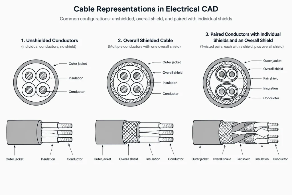
Pair and overall shields
Some cable constructions include shields around individual pairs or groups as well as an overall shield. A single outline around all conductors would not communicate that structure. Use nested envelopes, separate identifiers, or a simplified cable-construction diagram so the reader can distinguish pair shields from the overall shield.
If nested graphics become difficult to read, move the cable construction to a dedicated detail and reference it from the interconnection diagram. Readability is more useful than attempting to place every layer of information in one small symbol.
Showing termination intent clearly
The most important drafting question is not merely whether a shield exists, but what happens at each end. A shield line that stops near an enclosure without a symbol, terminal ID, or note leaves the connection ambiguous.
At each cable endpoint, document the applicable condition using a consistent project convention. Possible drawing conditions include:
- Connected to an identified terminal.
- Connected to a designated bar or reference point.
- Bonded to an enclosure or connector shell where required by the design.
- Continued through a connector or intermediate junction.
- Isolated and not connected at that endpoint.
- Handled internally by packaged equipment and referenced to vendor documentation.
Avoid using a generic ground symbol as a substitute for termination information. Ground-related symbols can represent different concepts, and their meaning may vary by drawing type. Pair the symbol with an identifier, terminal reference, or explanatory legend entry.
Document both ends
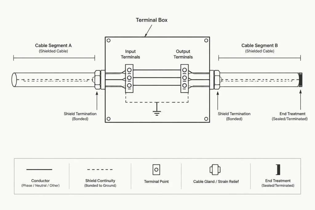
Showing one endpoint and leaving the other unmarked can create an unintended assumption. Even when the project design calls for no connection at an endpoint, the drawing should communicate that condition deliberately. A short note, an identified insulated endpoint symbol, or a referenced typical detail can distinguish intentional isolation from missing drafting.
Intermediate junctions
Cables may pass through terminal boxes, marshalling cabinets, patch points, or connectors before reaching the final device. The drawings should indicate whether shield continuity passes through the intermediate point, terminates there, or changes to another cable segment.
Give each segment a cable ID when it is separately scheduled or installed as a distinct cable. Do not draw several physical cable segments as one uninterrupted line if doing so hides terminal or connector boundaries.
Building reusable CAD blocks
A shield symbol block should support consistency without forcing every situation into one graphic. Useful block families may include an overall shield envelope, a shield termination marker, an isolated endpoint marker, a drain wire identifier, and a continuation reference.
Keep editable project data separate from fixed geometry. Attributes can carry information such as:
- Cable identifier.
- Shield or drain designation.
- Terminal reference.
- Destination drawing or detail.
- Endpoint condition.
Use attributes selectively. If a symbol requires many hidden or overlapping fields, a schedule or dedicated termination table may be easier to review. Block names should distinguish graphic purpose rather than implying that one symbol is universally correct for every cable system.
Place shield graphics and labels on layers that fit the project’s diagram organization. Separating cable conductors, shield boundaries, terminal symbols, and annotations can help with editing and plotting, but critical meaning should not disappear when an optional layer is turned off.
Coordinate the cable schedule
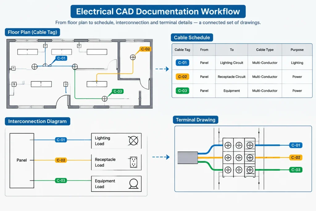
The cable schedule should use the same cable ID shown on plans and diagrams. If the schedule records shield information, use controlled wording rather than inconsistent free-form abbreviations.
Useful schedule fields may include cable ID, origin, destination, service or system, conductor description, shield configuration, termination detail reference, and remarks. Whether each field is needed depends on the project and the role of the schedule.
A complex termination instruction should not be compressed into a small schedule cell if that makes it difficult to interpret. Instead, reference a wiring diagram, terminal drawing, or project-specific detail. The schedule identifies the cable; the diagram explains the connection.
Legend and notation guidance
Add shield conventions to the drawing legend when their meaning is not already unmistakable. The legend can explain the shield envelope, drain wire line, termination marker, isolated endpoint, and continuation notation.
Use notes to define the graphical language, not to make undocumented design decisions. Broad statements about how every shield must be connected can conflict with equipment-specific requirements or approved design intent. Where arrangements vary, show the condition for each cable or define clear categories with referenced details.
CAD quality-control workflow
A focused review can catch most shield-documentation problems before issue:
- Confirm every shielded cable has a consistent ID across diagrams and schedules.
- Check whether each shield boundary surrounds the intended conductors or pairs.
- Verify that drain wires are not confused with grounding or signal conductors.
- Review both cable endpoints for an explicit termination or isolation condition.
- Trace shield continuity through intermediate boxes, connectors, and terminals.
- Confirm terminal identifiers match terminal drawings and equipment references.
- Check that shield graphics remain readable in the intended plot style.
- Search for copied symbols whose attributes still contain an earlier cable ID.
- Compare typical details with exceptions shown elsewhere in the set.
- Make sure plan, diagram, and schedule references lead to the correct location.
The final goal is traceability. A reviewer should be able to start with a cable tag on a plan, locate the cable in the schedule, follow it on the relevant diagram, and understand the documented shield treatment at every endpoint. Clear CAD conventions make that path possible without treating a generic symbol as a substitute for verified project design.
A practical documentation review framework
Review shielded-cable documentation as a connected information path rather than as an isolated symbol check. Begin with the cable identifier, follow its drawing references, compare its endpoints with the schedule, and confirm that the shield and drain wire retain the same meaning in every view.
Separate identity, construction, and termination
These are related but distinct documentation topics. The cable identifier establishes which cable is being shown. The construction description indicates whether shielding applies to the complete cable or to selected conductor groups. The termination graphics explain what happens to the shield or drain wire at each documented endpoint.
Keeping these topics distinct makes revisions easier. A cable can retain its identity while its routing reference, construction description, or endpoint treatment is updated through the approved design process.
Make exceptions visible
Typical details are useful when many cables share a documented arrangement, but they can conceal exceptions. Mark any cable that differs from the typical condition and direct the reader to the applicable diagram, note, or termination detail. An exception should not depend on a reviewer noticing a subtle graphical variation.
Check the drawing handoff
Before issue, review the documents in the sequence a technical user is likely to follow. Confirm that a cable tag leads to the correct schedule entry, that the schedule points to the relevant diagram, and that the diagram identifies both endpoint conditions. Also confirm that continuation references do not create gaps at connectors, cabinets, or intermediate terminal locations.
Preserve meaning outside the CAD authoring environment
Shield boundaries, isolated endpoints, and drain-wire labels should remain understandable in plotted output and exchanged files. Use geometry, linetypes, text, and legend definitions together so that essential meaning does not depend on color, layer naming, or software-specific display behavior.
Frequently asked questions
Is a shield symbol the same as a drain wire symbol?
No. The shield represents the conductive layer associated with the cable conductors, while the drain wire is a separate conductor associated with certain shield constructions. A drawing should distinguish them whenever both are relevant.
Should every drawing show the complete shield termination arrangement?
Not necessarily. Plans and system diagrams may identify the cable and provide references, while wiring or terminal drawings show endpoint details. The important requirement is that the drawing set provides a clear path to the complete documented condition.
Can a generic ground symbol identify a shield termination?
A generic symbol by itself may be ambiguous. Add a terminal identifier, connection label, legend definition, or detail reference that communicates the intended drawing meaning.
How should an unconnected shield endpoint be shown?
Use the project’s defined isolated-end symbol, note, or detail reference. An intentional nonconnection should be visibly documented rather than represented by a line that simply stops.
What belongs in the cable schedule?
The schedule can coordinate the cable identifier, endpoints, system or service, conductor description, shield configuration, and relevant drawing references. Detailed connection graphics are generally clearer on a wiring, terminal, or project-specific detail drawing.
How can copied CAD blocks create errors?
Copied blocks may retain cable tags, terminal references, endpoint descriptions, or hidden attributes from an earlier connection. Review block attributes and cross-references after copying or arraying symbols.
What should be checked when a cable passes through an intermediate enclosure?
Confirm whether the drawing shows shield continuity, a local termination, or a transition to another identified cable segment. Coordinate that condition with terminal drawings, connector references, and the cable schedule.












Leave a Reply
You must be logged in to post a comment.