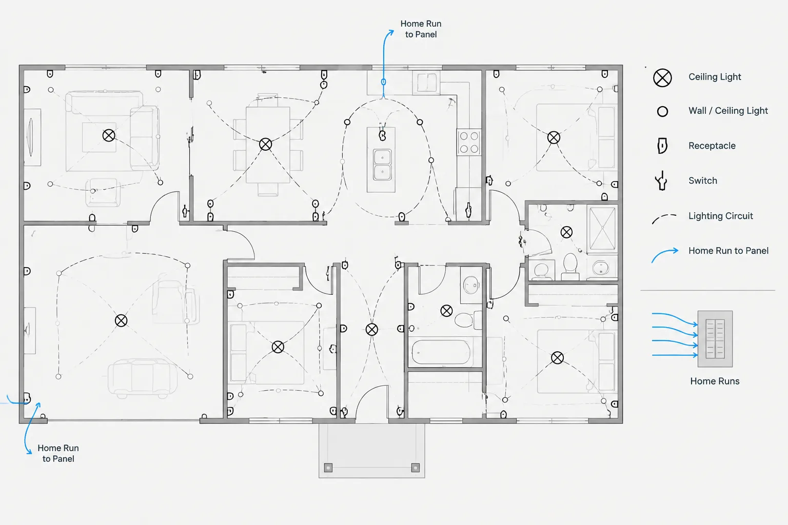
Electrical circuiting linework in CAD is more than a set of curves drawn between symbols. Its geometry, layer, line type, connection points, and annotations collectively tell the reader whether devices share a circuit, participate in a control relationship, connect to a source, or follow an intended pathway.
This reference explains how to select and manage arcs, polylines, home runs, crossings, and continuation graphics without implying information the drawing does not establish. The emphasis is on readable documentation, efficient editing, and consistent interpretation across electrical plans, diagrams, schedules, and related views.
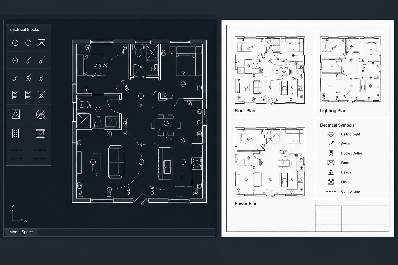
Electrical circuiting linework connects devices graphically, but its meaning is not always obvious. A curved line between receptacles may indicate a shared branch circuit, a switching relationship, or an intended cable route depending on the drawing type and project conventions. If those meanings are not defined, even neat CAD linework can create confusion.
A reliable drafting workflow separates electrical relationships from physical routing. It also establishes consistent rules for line shape, layer assignment, intersections, home runs, continuations, and annotation. The objective is not to make every circuit line look identical. It is to help readers understand what is connected, where the information continues, and whether the line represents design intent or an actual pathway.
What Circuiting Linework Communicates
On a typical electrical plan, circuiting graphics may communicate one or more of the following:
- Devices connected to the same branch circuit
- The sequence in which devices are grouped on the drawing
- A connection between a control device and controlled equipment
- A home run or other reference back to a panel or source
- A continuation to another area, sheet, or view
- An approximate raceway, cable, or wiring path
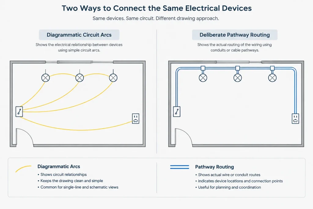
These are different kinds of information. A diagrammatic arc connecting several receptacles does not necessarily show the installed raceway route. Conversely, a line on a pathway plan may be intended to represent coordinated routing through rooms, shafts, or overhead spaces.
The drawing notes, legend, line types, and sheet title should establish which interpretation applies. Avoid relying on visual appearance alone when two types of lines could be mistaken for each other.
Diagrammatic Connections Versus Physical Routing
Before drafting circuit lines, determine whether the plan is relationship-based or route-based.
| Linework approach | Primary purpose | Typical drafting emphasis |
|---|---|---|
| Diagrammatic circuiting | Shows which devices belong together electrically | Clear grouping, circuit identification, and readable connections |
| Approximate routing | Shows general pathway intent without defining every bend | Coordination with rooms, major obstacles, and equipment locations |
| Coordinated routing | Documents a more deliberate pathway arrangement | Route continuity, transitions, crossings, sections, and related details |
| Control relationship | Associates switches, sensors, relays, or controllers with controlled loads | Unambiguous control zones and separation from power circuiting |
Do not make diagrammatic circuit lines appear more precise than the underlying design information. Following walls and corridors with exact-looking bends can imply a physical routing decision even when the line only groups devices. If routing is not being documented, use a simple graphic convention and explain it in the drawing legend or notes.
Choosing Arcs, Polylines, and Other Line Types
Arcs for simple circuit grouping
Arcs are commonly used to connect nearby plan symbols without resembling architectural geometry. Their curved form can help readers distinguish electrical relationships from walls, casework, and grid lines. Arcs work well for short device-to-device connections where the sequence remains easy to follow.
However, a chain of individually drawn arcs can become difficult to revise. Small gaps, uneven curvature, and disconnected endpoints may appear after devices move. Use consistent construction methods and inspect the complete circuit after editing symbol locations.
Polylines for continuous editable paths
A polyline can be useful when one circuit path contains multiple segments or must be selected and revised as a single object. It can also support consistent graphic properties along the path. Depending on office practice, straight and curved segments may be combined to create a clean diagrammatic connection.
Avoid adding unnecessary vertices. Excessive control points make linework harder to reshape and can produce visible kinks. A circuit path should contain only the geometry needed to communicate its relationship or route.
Straight lines for schematics and deliberate routing
Straight line segments are often appropriate in schematics, risers, and diagrams organized around buses, rails, or connection terminals. They can also indicate deliberate plan routing when paired with a clearly defined pathway convention.
On a floor plan, straight circuit lines may blend into architectural backgrounds. Layer color, plotted lineweight, screening, and line type should preserve a clear visual difference without overpowering device symbols and annotations.
Splines and freeform curves
Freeform curves can create smooth graphics, but they are often harder to control, trim, and revise consistently than simple arcs or polylines. They may also behave unpredictably when exchanged between CAD environments. Use them only when their shape provides a genuine documentation benefit and the project workflow can preserve them reliably.
Build a Clear Circuiting Hierarchy
Circuit linework should normally be subordinate to equipment and device symbols but strong enough to remain visible over the background. A useful visual hierarchy is:

- Primary information: electrical devices, equipment, and critical identifiers
- Secondary information: circuiting, control relationships, and home-run graphics
- Supporting information: architectural backgrounds and reference geometry
This hierarchy should be evaluated in the final plotted or exported format, not only on the CAD screen. A line color that appears distinct in model space may plot with the same weight as a wall, hatch, or furniture line. Review representative sheets at their intended output scale.
Layer Circuiting by Meaning
Separating circuit linework by purpose makes editing and review easier. The exact layer names should follow the project CAD standard, but useful categories may include:
- Power branch-circuit connections
- Lighting branch-circuit connections
- Lighting control relationships
- Emergency or backup-power circuiting
- Existing circuiting
- Demolition circuiting
- Pathway or routing graphics
- Circuit annotations and home-run labels
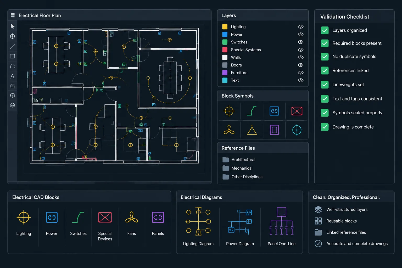
Do not create separate layers merely to compensate for inconsistent drafting. Layers should represent information that users may need to identify, isolate, plot differently, or manage by project phase. If two line categories have different meanings, their distinction should remain understandable when the drawing is printed without color.
Connect Lines to Symbols Consistently
Choose a repeatable rule for where circuit lines meet device blocks. Depending on the symbol, the line may connect to an insertion point, a defined connection point, or a clear edge location. The chosen method should avoid crossing through tags, attributes, or symbol graphics.
When a device moves, verify that its circuit connection moves or stretches correctly. Associating objects through grouping or other CAD management methods can help, but it does not replace visual review. Automated relationships may break when blocks are replaced, copied, mirrored, or transferred between files.
For devices placed close together, avoid creating a knot of overlapping arcs. It may be clearer to use a short shared branch, adjust the approach direction, or relocate the graphic connection while keeping the actual device symbol in its coordinated position.
Draft Home Runs as Complete Information Packages
A home-run graphic is useful only when readers can determine where the circuit originates or terminates. The arrow or directional mark should be coordinated with the adjacent text, panel identifier, circuit reference, and any applicable system designation.
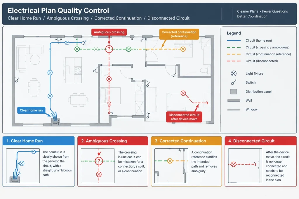
Keep the home-run label visually attached to the correct line. Crowded labels should not float between two circuits or overlap device tags. Where several circuits share a graphical home-run location, organize the annotation so each identifier can be traced to the intended circuit line.
Home-run arrows should not be used as substitutes for missing continuation information. If a circuit continues to another view or sheet, provide a defined reference rather than leaving the reader to infer the destination.
Manage Crossings, Breaks, and Continuations
Every apparent intersection should have a clear interpretation. Crossing lines may represent separate circuits, a connected junction, or unrelated systems superimposed on the same plan. Use the project’s established crossing and junction conventions consistently, and avoid intersections where a slight line adjustment would remove doubt.
When circuiting extends beyond a plan area, use a continuation symbol or reference with enough information to find the next segment. Match-line boundaries, enlarged plans, and partial plans require particular attention because circuit graphics can be clipped by viewports or duplicated across views.
During quality control, trace each interrupted circuit in both directions. Confirm that continuation labels match, duplicated segments agree, and no line ends unintentionally at a crop boundary.
A Practical CAD Drafting Workflow
- Define the intent. Decide whether the linework shows electrical relationships, approximate routing, coordinated routing, or controls.
- Confirm the convention. Review the project legend, notes, layer rules, and plotting hierarchy before drawing circuits.
- Place and verify devices first. Circuiting should follow coordinated device locations rather than conceal uncertain placement.
- Draw the simplest readable connection. Use minimal vertices and avoid decorative curves that add no information.
- Add source and circuit references. Coordinate home runs, panel names, circuit identifiers, and continuation marks.
- Separate overlapping meanings. Keep power circuiting, control relationships, and physical pathways visually distinguishable.
- Review at output scale. Check line hierarchy, crossings, labels, and background interference in the plotted view.
- Trace circuits during quality control. Follow each line from device group to source reference and compare it with related schedules or diagrams.
Common Circuiting Linework Problems
- False routing precision: Diagrammatic lines closely follow walls and imply an installation route that was never coordinated.
- Unattached home-run labels: Text appears near several lines without a clear graphical association.
- Mixed control and power graphics: Similar lines are used for different relationships without a legend distinction.
- Broken connections after edits: Devices move while arcs or polylines remain at their former locations.
- Ambiguous crossings: Readers cannot determine whether intersecting lines connect.
- Excessive linework: Every device is connected with elaborate curves, obscuring symbols and room information.
- Viewport clipping: A circuit disappears at a view edge without a continuation reference.
- Schedule disagreement: Plan labels do not match the associated panel, circuit, or equipment documentation.
Final Review Principle
Good electrical circuiting linework is economical and explicit. It uses only enough geometry to communicate the intended relationship, while annotations and references provide the information that geometry cannot. Before issuing a drawing, ask whether a reader can trace each circuit, distinguish it from control or routing graphics, identify its source reference, and recognize where it continues. If any answer depends on guesswork, the linework or its supporting documentation needs refinement.
Coordinate Circuit Graphics Across the Drawing Set
A circuit line should not be evaluated only within the floor plan where it appears. Its identifiers may also occur in panel documentation, equipment schedules, control diagrams, risers, details, and other plan areas. These references should describe the same electrical relationship even when each view uses a different graphic format.
Before issuing a drawing set, compare circuit labels and source references across related documents. Check that renamed panels, relocated equipment, revised device groups, and changed plan boundaries have not left obsolete linework or annotations behind. This comparison is especially important after copying typical areas or reusing content from an earlier design stage.
Preserve Meaning During CAD Exchange
Circuiting may look correct in the authoring file but change when exported, referenced, flattened, or opened in another CAD environment. Complex curves can be segmented, custom line types can display differently, and annotation associations can be lost. The resulting geometry may remain visible while its intended relationship becomes less clear.
Favor durable objects and explicit annotation over effects that depend on a particular display configuration. Review exchanged files for missing endpoints, altered curves, displaced labels, hidden layers, and line types that no longer distinguish circuiting from pathways or controls.
Use Data and Graphics as Complementary Information
Object properties, block attributes, or external design data may help manage circuit assignments, but visible plan graphics still need to communicate clearly in the issued document. A database association cannot resolve an ambiguous crossing or identify an unlabeled continuation for someone reviewing a plotted sheet.
Likewise, visually connected symbols do not prove that the underlying object data is correct. Where a workflow uses both graphic circuiting and structured information, quality control should compare them rather than assuming one automatically validates the other.
Questions for a Focused Linework Review
- Can each device group be followed to a source or defined continuation?
- Does the geometry represent a relationship, a route, or a control function, and is that meaning stated?
- Are circuit lines visually subordinate to symbols and identifiers?
- Can crossings and junctions be interpreted without relying on color?
- Do moved or replaced blocks still meet their intended circuit lines?
- Are labels attached clearly enough to avoid association with a neighboring circuit?
- Do related plans, diagrams, and schedules use matching references?
- Does the linework remain understandable after plotting or file exchange?
Frequently Asked Questions
Should circuit lines show the actual cable or raceway route?
Only when the drawing purpose and project conventions define them as routing information. Many floor-plan circuit lines are diagrammatic and show electrical grouping rather than the installed pathway. Notes, legends, layers, and related details should make the distinction clear.
Are arcs or polylines better for electrical circuiting?
Neither object type is universally better. Arcs can create simple, recognizable device connections, while polylines can make a longer path easier to select and revise as one object. Choose the method that remains readable, editable, and compatible with the project workflow.
What information should accompany a home run?
A home run should be associated clearly with its source or destination reference and the applicable circuit identification. The arrow, line, and text should function as one readable information group rather than as separate nearby objects.
How should crossing circuit lines be handled?
Apply the established junction and crossing convention consistently. If a crossing could be interpreted as a connection, adjust the geometry or use the defined graphic treatment so the reader does not have to guess.
Why should power circuiting and control relationships use different conventions?
They describe different electrical relationships. Distinct layers, line types, annotations, or other documented conventions help prevent a control association from being mistaken for branch-circuit wiring or physical routing.
What should be checked after devices are moved?
Review connected line endpoints, curves, home runs, labels, crossings, and related references. Grouping or associative CAD behavior can help with revisions, but the updated plan still requires visual verification.










Leave a Reply
You must be logged in to post a comment.