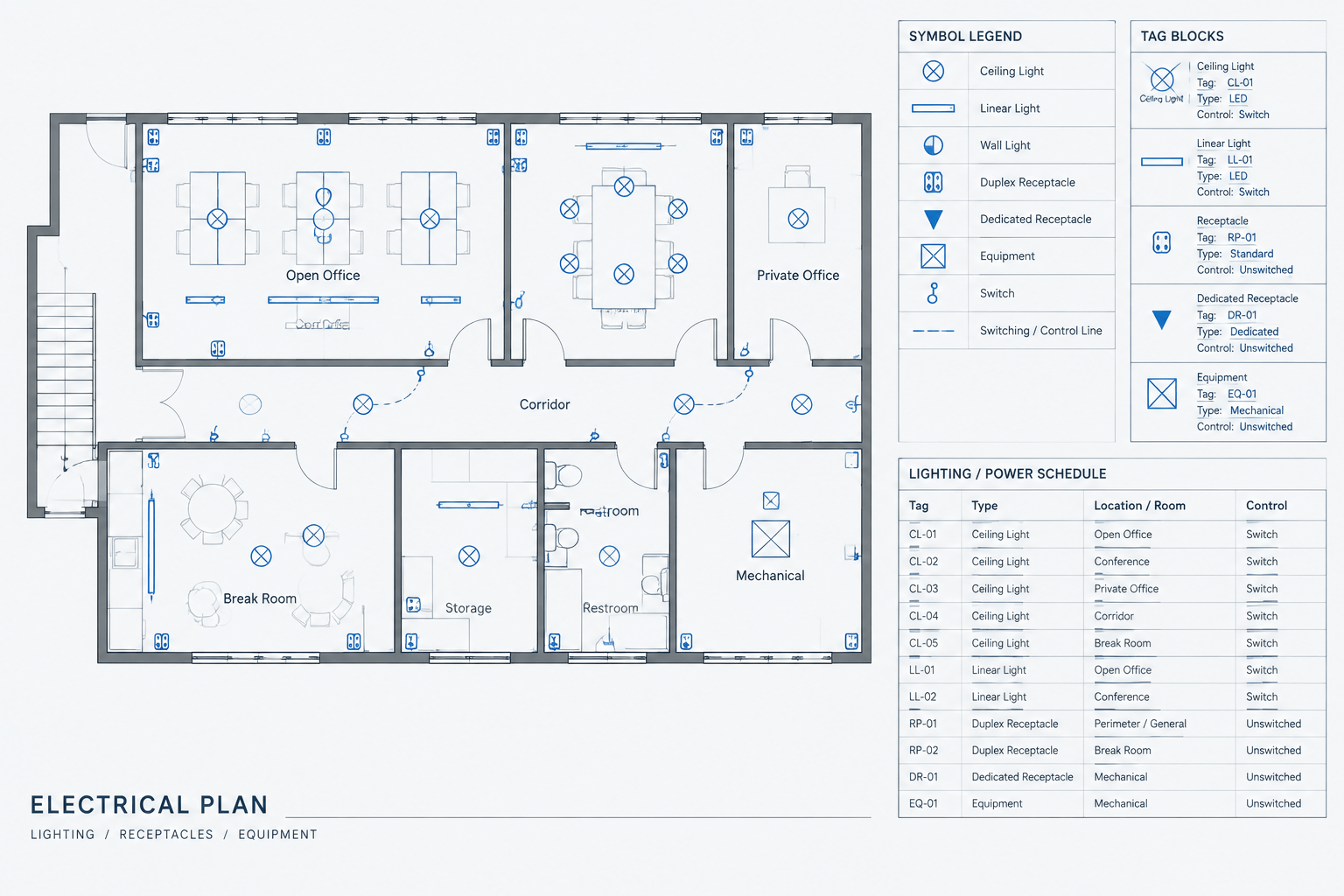
Electrical CAD block attributes help connect plan graphics with the identifiers and references used throughout a drawing set. When their fields are planned carefully, attributed symbols can reduce disconnected annotation, support data extraction, and make schedule coordination easier to review.
The value of an attribute system depends on consistency rather than the number of fields included. Block names, attribute tags, visible labels, layers, and schedule keys should follow the same documentation logic. The guidance below focuses on building that logic without treating extracted CAD data as a substitute for project-specific design review.
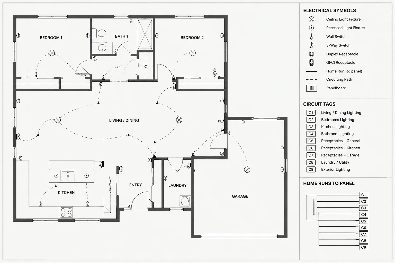
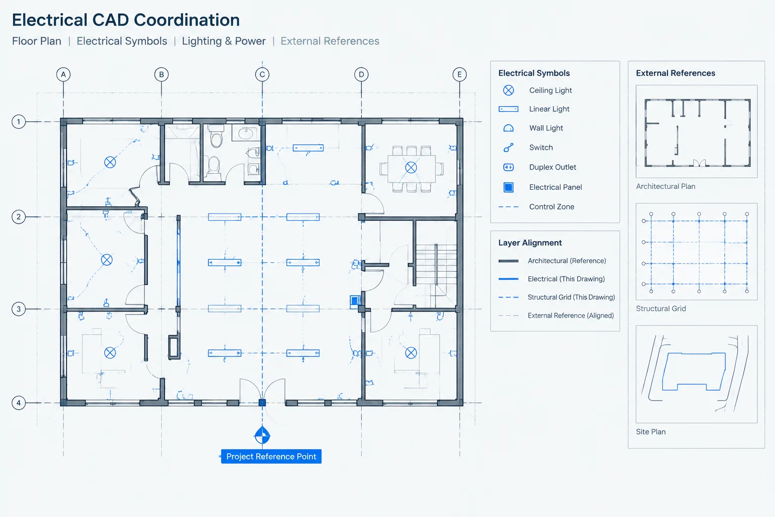
Electrical symbols often begin as simple collections of lines, arcs, and text. That may be enough to show a receptacle, light fixture, disconnect, sensor, or panel on a plan, but graphical geometry alone cannot reliably carry all the information needed for coordination. Electrical CAD block attributes add structured text and data to a symbol so that the same block can support plan identification, schedules, quantity reviews, and drawing quality control.
The goal is not to place every design property inside every block. A useful attributed symbol carries only the information that belongs with the represented object and can be maintained consistently. This guide explains how to plan that information, separate visible annotations from background data, and avoid common attribute problems.
What Is an Electrical CAD Block Attribute?
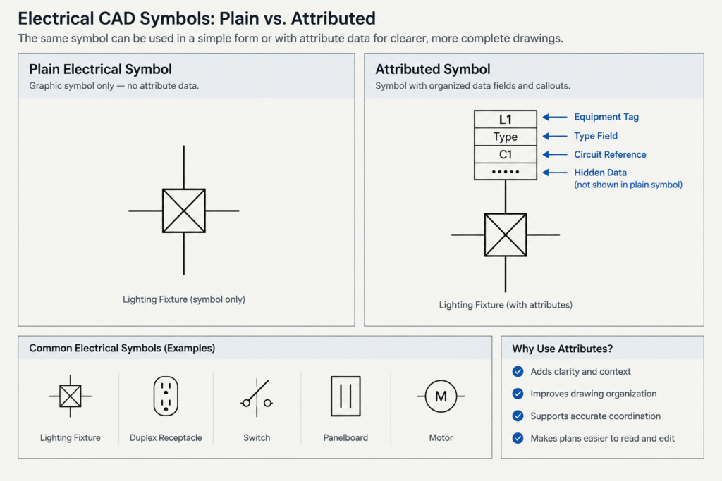
A block attribute is a defined data field associated with a CAD block. When the block is inserted, the user can enter or confirm a value for that field. Depending on how the block is configured, the value may appear beside the symbol or remain available as non-plotting object data.
For example, a light fixture symbol might include fields for a fixture type, circuit reference, control designation, mounting note, and remarks. A distribution equipment block might carry an equipment tag and source reference. The block geometry communicates the object category, while the attributes distinguish one instance from another.
This distinction matters because ordinary text placed near a symbol has no dependable relationship to that symbol. It can be moved, copied, or deleted independently. An attribute remains associated with the block instance, making it easier to inspect and extract.
Attributes, Static Text, and Schedule Data
Not every label should become an attribute. The appropriate method depends on what the information means and how it will be maintained.
| Information method | Best use | Main limitation |
|---|---|---|
| Static text inside a block | Text that is identical for every instance of the symbol | Changing the block definition may affect every instance |
| Block attribute | Values that may differ between individual symbol instances | Requires a controlled field structure and editing workflow |
| Separate plan annotation | Notes that describe an area, route, or group of objects | May not remain associated with a specific block |
| External schedule or database field | Detailed information managed outside the plan symbol | Needs a stable identifier to connect it to the drawing |
A practical rule is to use static block text for a fixed graphical convention, attributes for instance-specific identification, and schedules for detailed properties shared by a type or equipment record. Project needs vary, so the project’s drafting standard and deliverable requirements should control the final structure.
Plan the Attribute Set Before Editing Blocks
Adding fields without a plan often produces duplicate information, inconsistent abbreviations, and crowded drawings. Begin by listing what users must read directly from the plan and what the documentation team may need to extract later.
Identify the object’s stable key
Most schedule-connected objects need a stable identifier. Depending on the drawing type, this may be a fixture type, equipment tag, device number, panel designation, or another project-defined reference. The identifier should use the same naming convention on plans, diagrams, details, and schedules.
Separate type data from instance data
Type data describes a category shared by multiple objects. Instance data describes one placed object. A fixture type is usually shared, while a circuit reference may vary by location. Mixing these concepts can create unnecessary repetition and make later revisions harder to manage.
- Possible type data: symbol classification, fixture type, device family, or equipment category.
- Possible instance data: unique tag, circuit reference, control reference, source designation, or location note.
- Possible schedule-only data: extended descriptions, procurement information, or detailed project criteria that would clutter the plan.
Decide which values must be visible
A field can be useful for extraction without appearing on a plotted sheet. Visible attributes should support plan reading. Hidden or non-plotting data can support filtering, reports, or internal checking, but it should not become a substitute for information that reviewers need to see.
Use Clear and Durable Attribute Names
Each attribute definition normally has an internal tag or field name, a prompt shown during entry, and a default value. These elements serve different purposes and should be written deliberately.
- Internal tag: Use a concise, stable name that identifies the data field. Avoid changing it casually after blocks are already in use.
- User prompt: Write a plain-language instruction that makes the expected value clear.
- Default value: Use a safe placeholder or common value only when it cannot be mistaken for confirmed design information.
For example, tags such as EQUIPMENT_TAG, FIXTURE_TYPE, and CIRCUIT_REF are easier to understand than vague labels such as TEXT or DATA. The exact convention can vary, but consistency is more important than personal preference.
Design the Annotation for Real Plan Conditions
An attributed block should remain readable when it is placed in a dense electrical plan. Test more than an isolated symbol on a blank screen.
Establish an annotation hierarchy
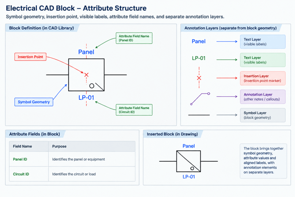
The primary identifier should be visually distinct from secondary information. A fixture type or equipment tag may need more emphasis than a circuit or control reference. Avoid giving every field equal prominence, because that makes the annotation harder to scan.
Choose predictable insertion and alignment points
Consistent text placement reduces cleanup after insertion. Align related fields so they form a recognizable label group. The block’s insertion point should also match its intended plan use, such as the center of a device symbol or a meaningful equipment reference point.
Account for rotation and mirroring
Electrical symbols are frequently rotated to suit walls, rooms, equipment orientations, and diagram layouts. Test whether attribute text remains legible and correctly positioned after permitted transformations. Mirrored text or labels that rotate into adjacent geometry are signs that the block behavior needs refinement.
Control layers intentionally
Symbol geometry and annotation may require different display or plotting control. Place attribute definitions on layers that match the project’s layer strategy rather than relying on arbitrary current-layer settings. Also confirm that required text is not assigned to a non-plotting layer.
Connect Attributed Symbols to Schedules
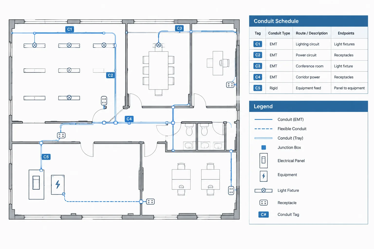
Attributes become particularly valuable when block data is extracted into a schedule or review table. A successful workflow depends on predictable block names, consistent attribute tags, and disciplined values.
Before relying on extracted information, decide what one row represents. It may represent each symbol instance, each unique equipment tag, or a summarized count by type. These are different outputs and should not be mixed unintentionally.
A dependable workflow generally follows these stages:
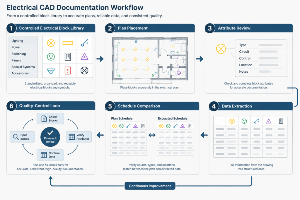
- Place symbols from a controlled block library.
- Enter project values using agreed naming and abbreviation rules.
- Review visible labels in the drawing context.
- Extract the required fields from selected blocks.
- Check for blanks, unexpected values, duplicates, and naming variations.
- Compare the resulting data with the project schedule and diagrams.
- Recheck the output after design revisions.
Data extraction does not prove that the electrical design is correct. It only reports what has been entered and selected. The extracted result still requires technical and documentation review.
Avoid Duplicate Sources of Truth
A common documentation problem occurs when the same fact is typed independently in several places. For example, an equipment tag may appear as an attribute, separate text, a schedule entry, and a diagram label. If each copy is edited manually, mismatches are likely.
Choose a controlled source for each information category and establish how other drawing elements refer to it. Even when the CAD workflow cannot update every reference automatically, a clearly defined source makes manual checking more reliable.
Do not place detailed schedule content inside a block simply because fields are available. Excessive data increases maintenance effort, slows review, and can encourage users to treat an outdated block value as authoritative.
Common Attribute Problems and Their Causes
| Problem | Likely cause | Drafting response |
|---|---|---|
| Identical devices use different field names | Blocks were created from unrelated sources | Map the library to a shared attribute convention |
| Schedule contains blank records | Required fields were skipped or hidden during insertion | Review prompts, defaults, and completeness checks |
| Attribute values do not match visible text | Separate text was placed over or beside the block | Remove duplicate annotation and clarify the controlling field |
| Labels overlap walls or other symbols | The block was tested only in isolation | Test typical plan density, rotation, and label positions |
| Existing blocks do not show revised definitions | Block instances and attribute definitions were not synchronized | Use the CAD platform’s verified update procedure and review results |
| Counts include unwanted symbols | Extraction filters are too broad | Filter by controlled block identity and relevant fields |
Quality-Control Checklist for Attributed Electrical Blocks
- Confirm that the block name identifies the correct symbol category.
- Verify that internal attribute tags follow the library convention.
- Check that prompts explain what users should enter.
- Remove misleading defaults that resemble completed design data.
- Confirm that required fields are visible or intentionally hidden.
- Test insertion, movement, copying, rotation, and approved mirroring behavior.
- Check text style, layer assignment, alignment, and plot visibility.
- Test the block in a representative plan rather than only in the editor.
- Run a sample extraction and inspect blanks, duplicates, and inconsistent values.
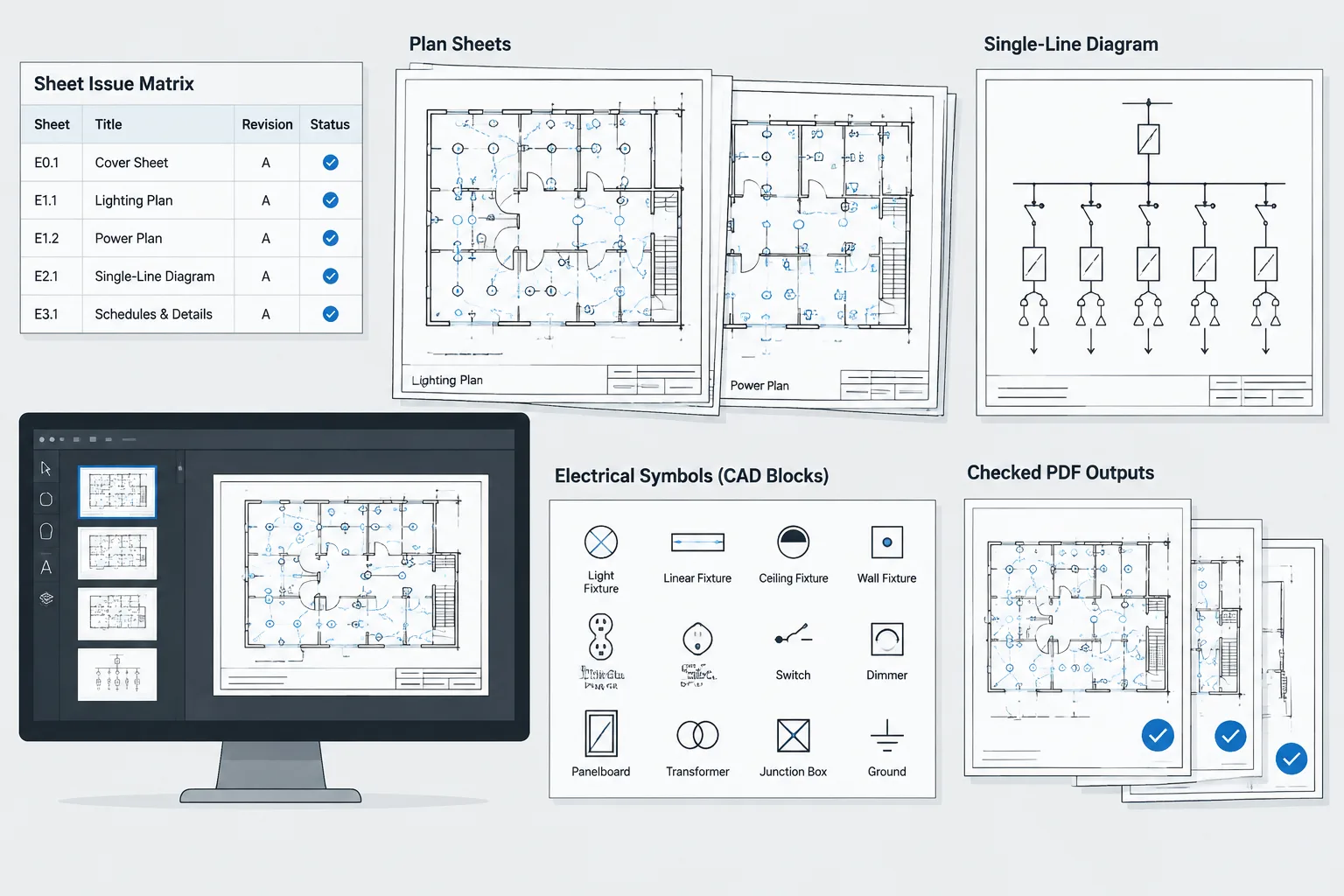
- Compare tags across plans, schedules, risers, and single-line diagrams.
- Verify all project-specific information before issuing the drawing.
Build a Library That Supports Documentation
A strong electrical CAD library is more than a collection of recognizable symbols. Its blocks should use consistent insertion logic, layers, annotation behavior, and data fields. Attributes can turn symbols into useful documentation objects, but only when their purpose is controlled.
Start with a small, repeatable field set based on real drawing needs. Keep plan labels readable, distinguish type data from instance data, and test extracted information before depending on it. Most importantly, treat attributed blocks as coordination tools rather than automatic proof of compliance or design suitability. Every symbol, value, schedule, and diagram reference must still be verified for the specific project.
Managing Attributes Through Drawing Revisions
Attribute planning should include the full documentation lifecycle, not only initial block creation. Symbols may be copied between plans, replaced from a library, renamed during coordination, or revised after schedules have already been prepared. Each of these actions can create stale, missing, or inconsistent values.
Before a revised drawing is issued, compare the current block instances with the approved library definitions and the controlling project records. Review both visible annotation and hidden extraction fields. A label may look correct on the plan while its underlying attribute contains an outdated spelling, an extra space, or a different abbreviation that separates it from related schedule records.
Review changes by information category
- Library changes: Confirm that revised definitions preserve required tags, prompts, layers, and annotation behavior.
- Instance changes: Check values edited for individual devices or equipment symbols.
- Schedule changes: Verify that schedule identifiers still correspond to the symbols shown on plans and diagrams.
- Extraction changes: Recheck selection filters, field mappings, grouping rules, and excluded blocks.
Use exception review instead of visual review alone
Visual plan review remains essential, but it may not reveal data inconsistencies. An exception review can focus attention on blank values, unexpected block names, duplicate identifiers, unrecognized abbreviations, and fields that do not match the project convention. These findings should be investigated rather than corrected automatically because an apparent duplicate or blank may have a legitimate documentation purpose.
A dependable attributed-block workflow therefore combines controlled library content, readable plan annotation, structured extraction, and deliberate revision checks. The final drawing team remains responsible for deciding which record controls and for verifying that plans, schedules, details, risers, and single-line diagrams communicate consistent information.
Frequently Asked Questions About Electrical CAD Block Attributes
Should every electrical symbol contain attributes?
No. Attributes are most useful when a symbol needs instance-specific identification, searchable data, or a reliable connection to another drawing record. A purely graphical symbol may not need attributed fields if no variable information belongs to the individual instance.
What is the difference between an attribute tag and its displayed value?
The tag identifies the field within the block definition, while the value is the project information stored in a placed block. Stable tags support consistent extraction even though the values differ among block instances.
Should hidden attributes contain information required to read the plan?
Generally, information needed by drawing reviewers should be visible through the appropriate plan label, note, or schedule reference. Hidden fields can support filtering and quality control, but they should not conceal information necessary to interpret the issued documentation.
Why can identical-looking symbols produce separate schedule records?
The blocks may have different names, attribute tags, spellings, spaces, or values. They may also have been created from unrelated library definitions. Review the underlying block identity and field structure instead of comparing appearance alone.
Can attribute extraction replace schedule review?
No. Extraction organizes selected CAD data, but it does not confirm that the values are technically correct, complete, current, or coordinated with the rest of the drawing set. The output still requires project-specific review.
What should be checked when an attribute definition changes?
Confirm how the CAD platform applies revised definitions to existing block instances. Then review field values, label positions, visibility, layers, and extraction results. Preserve valid project data and use the platform’s verified synchronization workflow rather than assuming every existing instance updated correctly.




Leave a Reply
You must be logged in to post a comment.