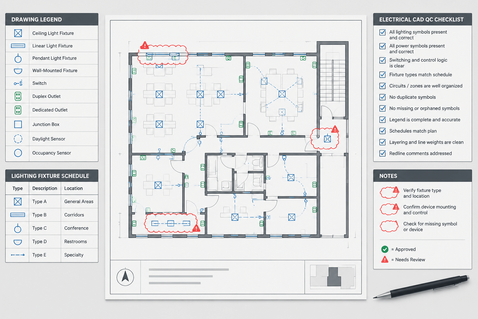
Before an electrical drawing set is issued, it should be reviewed as both a collection of CAD files and a coordinated communication package. A symbol may be drawn correctly yet conflict with a schedule, a reference may work on one workstation but fail in the release package, or an annotation may become unreadable in the plotted output.
The electrical CAD quality control checklist below organizes these concerns into practical review passes. It is intended to help drafters and reviewers find documentation inconsistencies while keeping engineering approval, code evaluation, and project-specific design decisions with the appropriate qualified team members.
An electrical drawing can look complete in the CAD workspace and still contain coordination errors that become obvious only after plotting or assembling the full issue set. Missing circuit tags, outdated backgrounds, inconsistent symbols, broken references, and unreadable notes are documentation problems that can obscure design intent.
A structured electrical CAD quality control checklist helps reviewers examine more than drafting appearance. It connects the floor plan to schedules, diagrams, details, legends, and other disciplines. The goal is not to approve the engineering design through drafting alone, but to confirm that the drawings communicate the documented design clearly and consistently.
Begin with the intended drawing issue
Before reviewing individual objects, identify what the drawing set is intended to communicate. A progress print, permit submission, coordination package, and construction issue may have different content and review expectations. The title block, issue description, revision information, and sheet list should all reflect the same stage.
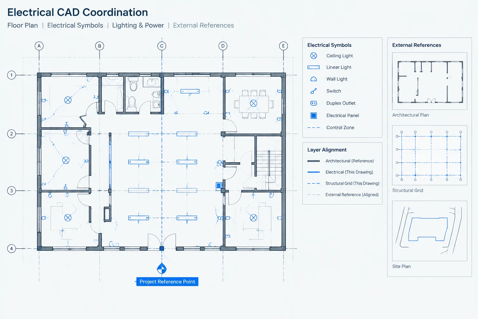
Confirm that the review uses the correct files rather than an older local copy, detached background, or superseded sheet export. Where a project uses external references, record which architectural, structural, mechanical, civil, or equipment backgrounds were included in the review.
Review the sheet at plotted scale
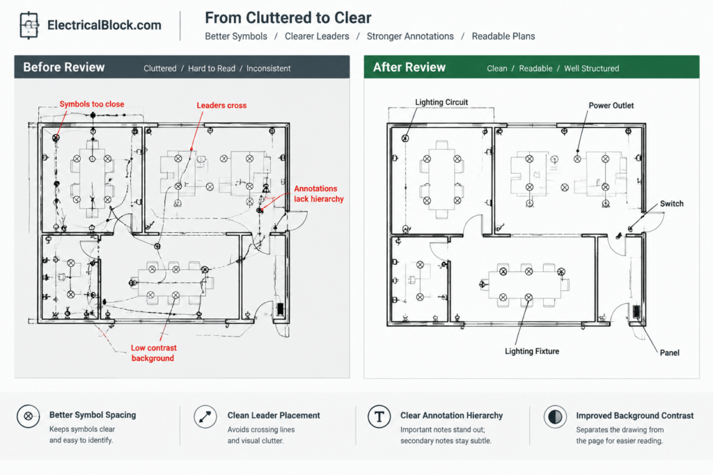
Model-space clarity does not guarantee sheet-space clarity. Electrical symbols may appear well separated while zoomed in but overlap walls, room names, ceiling grids, or dimensions when viewed at the intended plot scale.
- Generate a test plot or fixed-layout preview using the project plot configuration.
- Check lineweight contrast between electrical work, backgrounds, annotation, and overhead or concealed routing.
- Confirm that text is legible and does not merge with nearby geometry.
- Look for clipped notes, schedules, legends, revision marks, and viewport boundaries.
- Check that grayscale or monochrome output does not remove distinctions that were visible only through color.
- Verify that nonprinting construction geometry and viewport aids do not appear on the issued sheet.
Reviewing a reduced print can also reveal hierarchy problems. The main electrical information should remain identifiable without relying on extreme zooming.
Check symbols and CAD blocks
Symbols should communicate meaning consistently across the drawing set. A block that resembles the required device is not necessarily appropriate if its legend description, attributes, insertion behavior, or graphic convention differs from the project standard.
Symbol review questions
- Does every plan symbol have a corresponding legend entry or an otherwise established project meaning?
- Are similar devices represented by distinguishable symbols?
- Are block attributes complete, visible, and positioned consistently?
- Have mirrored or rotated blocks changed text orientation or symbol meaning?
- Are symbols placed on the intended electrical layers rather than inherited background layers?
- Have exploded blocks introduced disconnected lines, duplicate geometry, or inconsistent annotation?
Downloaded CAD blocks should be treated as source graphics, not automatic project standards. Review their units, layers, attributes, linework, and terminology before adding them to a production library. Their technical suitability must be verified for the specific project.
Trace circuits and drawing references
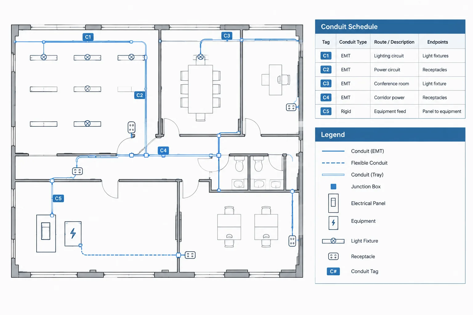
A circuit designation should lead the reader toward related documentation without guesswork. Review circuit tags, home-run indications, equipment identifiers, continuation notes, and diagram references as a connected information system.
- Compare plan circuit labels with the applicable panel or equipment schedule.
- Check that identifiers use the same spelling, punctuation, and naming pattern on every sheet.
- Trace continuation references in both directions.
- Confirm that detail, section, and enlarged-plan callouts point to an existing sheet location.
- Look for home runs or circuit lines that terminate without a clear destination.
- Check whether copied devices retained circuit data from their original location.
For larger plans, review one area at a time and mark each completed zone. A systematic sweep is more reliable than repeatedly scanning the entire sheet.
Coordinate plans, schedules, and diagrams
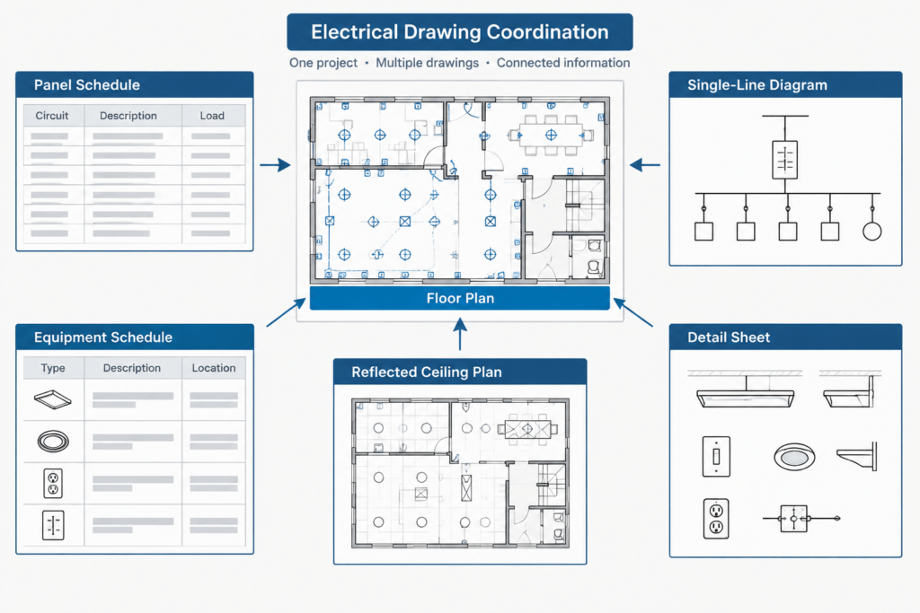
Many electrical drawing errors occur between documents rather than within a single sheet. A panel name may be correct on the plan but different on the single-line diagram. Equipment may appear in a connection schedule without a corresponding plan location, or a plan may show a device that is missing from the relevant schedule.
| Drawing relationship | Quality control check |
|---|---|
| Plan to panel schedule | Compare panel names, circuit identifiers, served spaces, and device associations. |
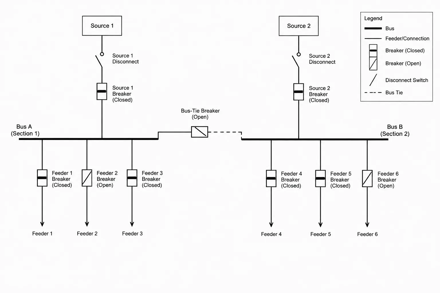
| Plan to single-line diagram | Confirm that distribution equipment identifiers and documented source relationships agree. |
| Plan to equipment schedule | Check that tagged equipment appears in the schedule and that schedule entries can be located on the plan. |
| Plan to reflected ceiling plan | Review lighting, ceiling-mounted devices, room layouts, and possible graphic conflicts. |
| Plan to details | Confirm that detail callouts are relevant to the condition shown and that identifiers match. |
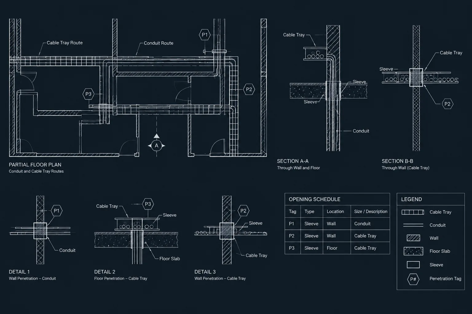
| Electrical to other disciplines | Review equipment locations, access areas, ceiling conditions, penetrations, and shared routing zones. |
This comparison is a documentation check. Electrical calculations, protective-device selection, conductor sizing, code compliance, and equipment ratings require qualified project-specific verification beyond a CAD review.
Inspect annotations and leaders
Notes should be close enough to their subjects to be understood without covering important geometry. Leaders should terminate clearly and should not cross unrelated symbols where that crossing could imply a connection.
Search for empty tags, placeholder text, duplicated note numbers, inconsistent abbreviations, and labels left behind after an object was moved or deleted. Review room-based notes after architectural updates because relocated walls and renamed rooms can change the meaning of nearby electrical annotation.
Audit layers and external references
Layer organization affects editing, plotting, file exchange, and future revisions. Objects placed on an incorrect layer may disappear in a viewport, plot with the wrong hierarchy, or become difficult to isolate.
- Check electrical objects for correct layer assignment and expected graphic properties.
- Identify unused, duplicate, imported, or ambiguously named layers for controlled cleanup.
- Confirm that referenced files resolve from the intended project location.
- Review reference visibility, clipping, display order, and plotted appearance.
- Make sure obsolete backgrounds are not hidden in the file and accidentally restored later.
- Inspect nested references for unexpected layers or geometry.
Do not delete unfamiliar layers or reference content solely because they appear unused. They may support title blocks, plotting, coordination overlays, or another discipline’s workflow.
Look for common CAD file problems
A visual review should be paired with a basic file-health check. Useful checks include overlapping duplicate objects, distant stray geometry, broken text styles, unexpected proxy content, inconsistent units, and blocks with excessively complicated internal geometry.
Also inspect drawing extents. An isolated object far from the project can disrupt zooming, exports, coordinate-based coordination, and file exchange. If an object appears unnecessary, determine its origin before removing it.
Use a staged electrical drawing review
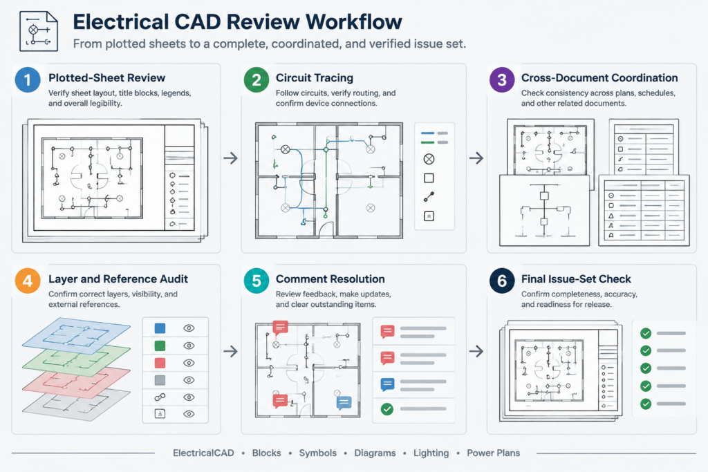
A single pass rarely catches every type of problem. A staged review keeps the reviewer focused:
- Graphic pass: Examine plotting, line hierarchy, text, symbols, and overall readability.
- Connectivity pass: Trace circuits, home runs, diagram relationships, and continuation references.
- Coordination pass: Compare plans with schedules, diagrams, details, and current background files.
- Data pass: Review tags, attributes, equipment names, sheet references, and revision information.
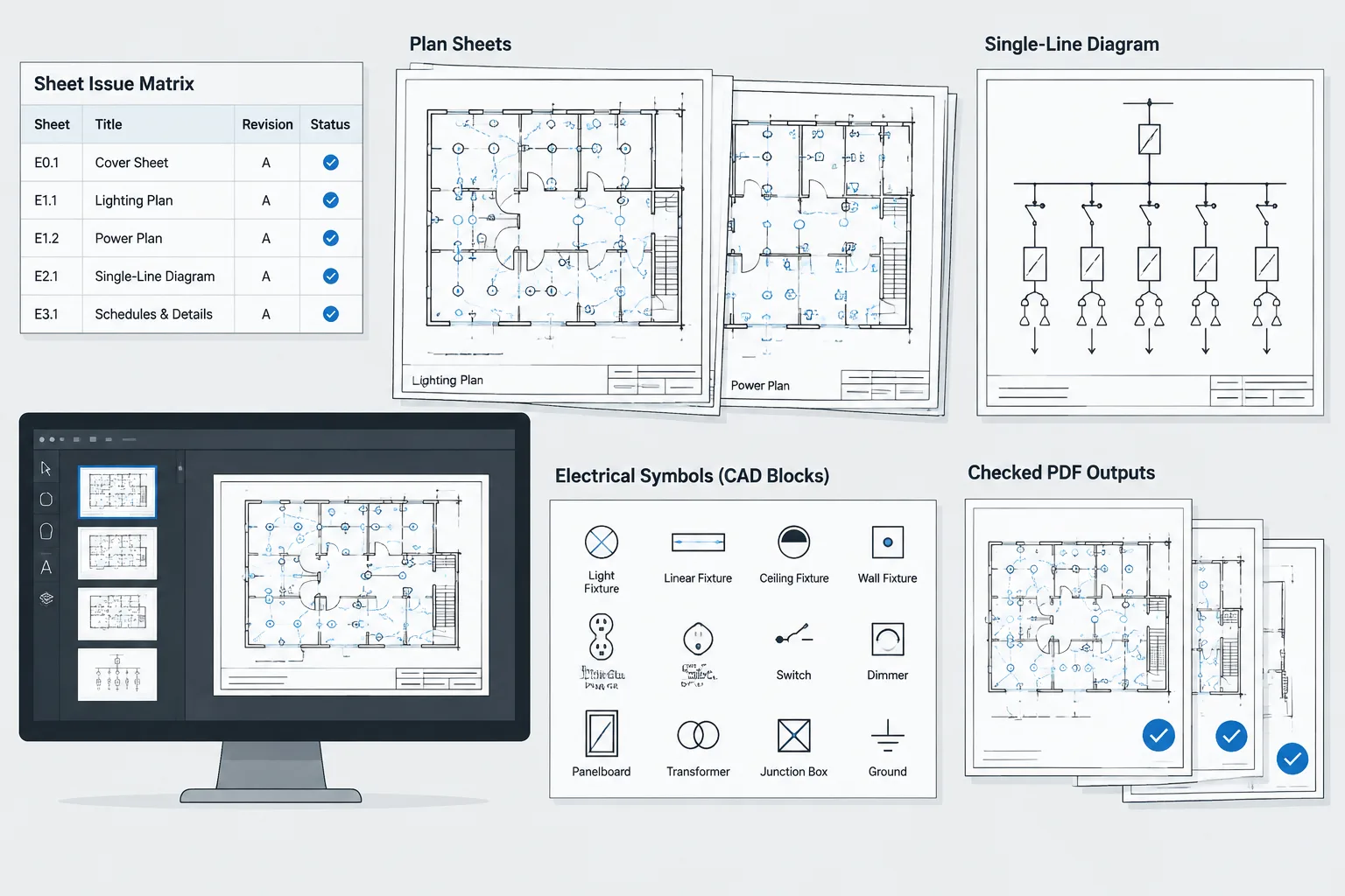
- Issue-set pass: Check sheet order, title blocks, file names, exports, and the completeness of the final package.
When possible, have someone other than the primary drafter perform at least one pass. A fresh reviewer is more likely to notice assumptions that became familiar during production.
Record findings so they can be closed
Quality control comments should identify a location, describe the problem, and indicate the drawing relationship that needs verification. A vague comment such as “check circuit” is less useful than a comment that names the device tag, sheet area, and conflicting schedule entry.
Track comments as open, resolved, or requiring design input. After corrections, verify the resulting output rather than checking only the editable CAD view. A change can solve one issue while creating another, such as moving a tag into a viewport crop or updating a plan identifier without updating the diagram.
Final pre-issue checklist
- The issue information and revision status are consistent across the set.
- Current backgrounds and external references are loaded correctly.
- Symbols, abbreviations, and tags agree with the drawing legend.
- Plan identifiers coordinate with schedules, diagrams, and details.
- References point to existing and relevant sheet locations.
- Text, leaders, linework, and symbols remain readable in the plotted output.
- Temporary graphics, placeholders, and unresolved markups are removed or addressed.
- The exported sheet set has been opened and reviewed as a complete package.
- Project-specific engineering and compliance items are directed to qualified reviewers.
An effective electrical CAD quality control checklist does more than produce a cleaner plot. It makes the drawing set easier to navigate, reduces contradictory information, and helps preserve design intent as documents move between drafters, engineers, contractors, owners, and future project teams.
Turn checklist results into review evidence
A checklist is most useful when it creates a traceable record rather than serving only as a reminder. Each finding should identify the affected sheet or file, the relevant drawing area, the type of conflict, and whether the correction requires drafting work or design input. The record should also show whether the resulting plotted or exported output was rechecked after the change.
Separate drafting corrections from design decisions
Some findings can be resolved through controlled documentation work, such as correcting a misplaced attribute, repairing a broken callout, or removing a confirmed placeholder. Other findings expose a conflict in the documented design, such as differing equipment identifiers or an unclear source relationship. The drafter should flag these conflicts rather than infer the intended engineering solution.
Review complete information paths
Instead of examining each sheet only as an isolated graphic, follow representative information paths through the set. Begin with a plan symbol, read its tag, locate its schedule entry, follow its circuit or source reference, and confirm any related diagram or detail. This approach helps reveal contradictions that may remain hidden during a sheet-by-sheet visual inspection.
Preserve the release state
The final review should address the actual package intended for distribution. Retain the reviewed export, resolved markup record, and relevant reference-file state according to the project documentation process. This makes it easier to distinguish the issued set from later working changes and helps future reviewers understand what was checked.
Electrical CAD quality control questions
Is CAD quality control the same as an electrical design review?
No. CAD quality control checks whether the drawings communicate the documented design consistently and legibly. Engineering calculations, equipment selection, electrical ratings, code compliance, and other project-specific design matters require qualified review beyond drafting checks.
Should reviewers check the native CAD file or only the plotted sheets?
Both views are useful. The native file reveals layer assignments, block behavior, references, attributes, and stray geometry. The plotted or exported package reveals clipping, line hierarchy, legibility, sheet order, and other issues that may not be apparent in the editing environment.
What should happen when a plan and schedule disagree?
The discrepancy should be recorded with enough context for the responsible project team member to resolve it. Reviewers should not silently choose one document as correct unless the project record clearly establishes the intended information.
How should downloaded electrical CAD blocks be reviewed?
Treat them as unverified source graphics until their layers, units, attributes, linework, terminology, and plotted appearance have been evaluated. Their technical meaning and project suitability must be confirmed before they become part of a production drawing library.
Why should the exported issue set be opened again?
Exporting can expose missing references, substituted fonts, clipped content, plotting differences, or incomplete sheets. Reviewing the assembled release package confirms that the deliverable communicates as expected rather than relying solely on the editable CAD view.






Leave a Reply
You must be logged in to post a comment.