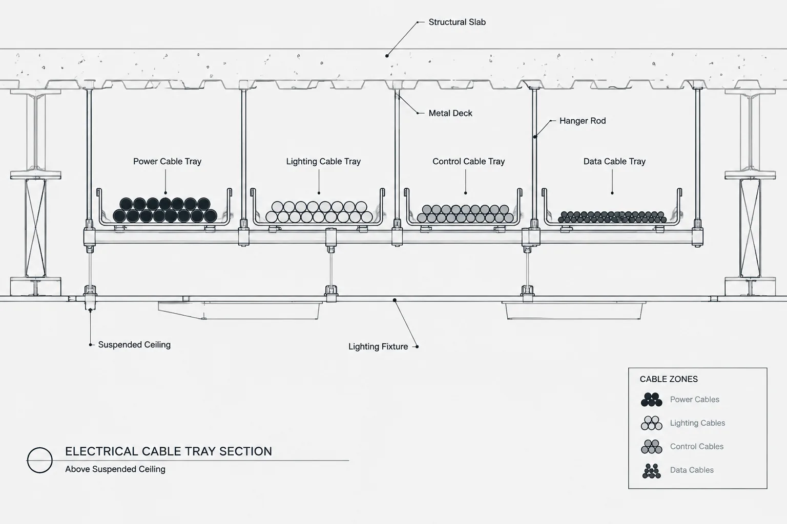
Cable tray cross-sections in CAD clarify routing conditions that are difficult to communicate with plan linework alone. They can show pathway relationships, cable-group intent, adjacent services, structural context, and links to schedules or other drawing views.
The key drafting challenge is distinguishing verified physical information from schematic organization. The following guide presents a documentation-focused workflow for producing readable sections without implying unsupported cable quantities, dimensions, clearances, or installation requirements.
A cable tray routing plan shows where a pathway travels, but it may not explain how cables are arranged within the pathway or how the route relates to nearby structure, piping, ductwork, and other electrical systems. Cable tray cross-sections add that missing documentation layer.
A useful cross-section is more than a rectangular tray outline filled with cable symbols. It should communicate the section location, viewing direction, tray identity, physical arrangement, cable-group intent, and relevant coordination constraints. It should also remain consistent with plans, schedules, risers, and installation details.
This guide explains a practical CAD workflow for creating cable tray cross-sections without treating a generic diagram as verified project design. Tray dimensions, loading, cable separation, support arrangements, bend requirements, and accessibility criteria must come from the applicable project documents, engineering decisions, manufacturer information, and governing requirements.
What a Cable Tray Cross-Section Should Communicate
The level of detail depends on the drawing purpose. A design drawing may show a representative cable arrangement, while a coordinated layout may need more precise tray positions and nearby obstructions. A fabrication-oriented document may contain information that does not belong in a general electrical plan.
At minimum, a cross-section should help the reader understand:
- Which tray route or segment is being shown.
- Where the section is cut and which direction the viewer is facing.
- Whether the tray is single-level, stacked, or installed beside another pathway.
- How cable groups are identified or logically separated.
- How the tray relates to ceilings, walls, structure, equipment, or other services.
- Which schedule, plan, detail, or note provides additional information.
A cross-section should not imply an exact cable count, tray loading, or separation method unless those items have been verified and intentionally documented.
Choose the Right Type of Section
Typical Section
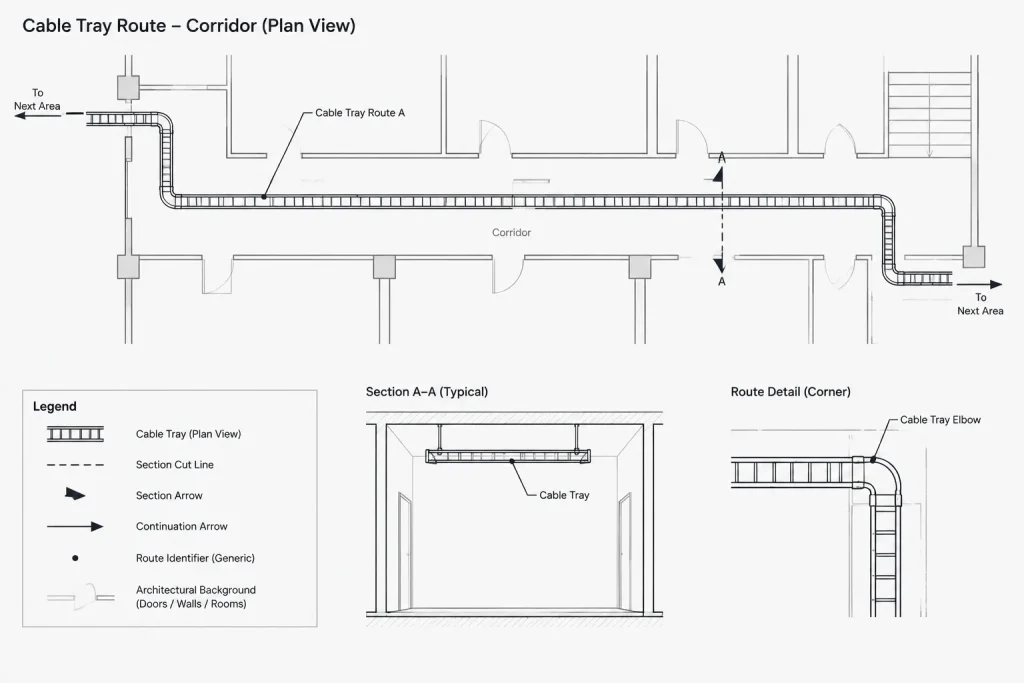
A typical section describes a recurring arrangement. It may show a tray above a corridor, stacked pathways in a service space, or a general relationship between power and communications pathways. Use a typical section only where the arrangement genuinely repeats. If field conditions vary substantially, a single typical detail can conceal important differences.
Location-Specific Section
A location-specific section is tied to a section marker on a plan. It is appropriate at congested crossings, changes in elevation, equipment approaches, shaft entries, or other areas where plan linework is insufficient.
The section identifier and sheet reference should match the plan callout. If the section is moved to another sheet during editing, update both ends of the reference.
Schematic Cable-Zone Diagram
A schematic diagram can explain cable-group organization without representing a measured installation. For example, it may identify portions of a pathway intended for different systems or show that certain cable groups occupy separate trays.
Label the diagram as schematic or diagrammatic when its geometry is not intended to be scaled. Avoid placing precise-looking dimensions on symbolic arrangements unless they represent verified criteria.
Build the Section from Coordinated References
Before drafting, collect the documents that define the route and its context. These may include the electrical routing plan, architectural sections, reflected ceiling information, structural framing, mechanical coordination drawings, tray schedules, cable schedules, and equipment connection information.
Use the references to answer several questions:
- Does the route identifier remain consistent through the section location?
- Is the tray elevation defined, estimated, or still subject to coordination?
- Are multiple trays shown separately on the plan or represented by one route line?
- Do nearby services affect the available routing zone?
- Does the route enter equipment, a shaft, or another drawing area?
- Is the section documenting design intent or a coordinated physical arrangement?
Do not convert an uncertain plan line into falsely precise section geometry. If information is unresolved, use an appropriate note, status indicator, or coordination callout rather than inventing a dimension.
A Practical CAD Drafting Workflow
1. Establish the Section Cut
Place the section marker where it captures the condition that needs explanation. The viewing direction should reveal the important relationships rather than looking into an obstruction or along the tray route.
Give the section a stable identifier early in the drafting process. Stable references make review comments and drawing comparisons easier to track.
2. Draw the Coordinated Background
Show only the architectural and structural context needed to understand the tray location. Walls, slab edges, beams, ceilings, and major coordinated services may be useful. Excessive background detail can bury the electrical information.
Apply a lighter graphic hierarchy to reference geometry. The tray, cable zones, identifiers, and electrical notes should remain visually dominant.

3. Draft the Tray Geometry
Represent the tray outline according to the purpose of the section. A coordinated section may use scaled geometry based on verified project information. A conceptual section may use simplified geometry, provided its diagrammatic nature is clear.
For stacked or adjacent trays, draw each pathway separately and identify it individually. Do not rely only on vertical or horizontal position to distinguish systems because that meaning may be lost when the detail is reused or revised.
4. Represent Cable Groups Carefully
Individual cable outlines are often unnecessary and can create maintenance problems when circuiting changes. Instead, use labeled cable zones, simplified bundles, or references to a cable schedule.
Possible zone labels include functional descriptions such as feeder cables, branch circuits, controls, communications, or project-specific system names. Use only categories that match the project documentation. If physical separation is required by the design, show the intended arrangement and direct the reader to the governing project criteria rather than embedding unverified rules in a generic detail.
5. Add Identifiers and References
Tray tags should match those used on routing plans and schedules. Where a route changes designation, make the transition clear. A reader should not have to infer whether two nearby tray outlines are parts of the same route.
Useful references may include:
- Tray or pathway identifier.
- Associated cable or pathway schedule.
- Plan and section references.
- Equipment destination or served area.
- Continuation reference.
- Support-detail reference, when relevant.
- Coordination note for unresolved conditions.
6. Add Dimensions Selectively
Dimension only information that is defined, useful, and controlled by the drawing. Potentially useful dimensions include verified pathway relationships, offsets from stable references, and coordinated elevations.
Avoid dimensioning to movable ceiling elements, temporary objects, or background geometry that is likely to change. Also avoid duplicating dimensions that are controlled by another discipline unless the duplicated information is coordinated and necessary.
Organizing Cable Zones Without Overstating Detail
Cable-zone diagrams are most effective when they communicate intent without pretending to predict the final resting position of every cable. Cable layouts can change as routing, circuiting, and equipment selections develop.

| Graphic approach | Best use | Primary caution |
|---|---|---|
| Labeled zones | Showing functional grouping within a tray | Do not imply exact occupied area unless verified |
| Simplified cable bundles | Illustrating general arrangement | Avoid suggesting a fixed cable count |
| Separate tray outlines | Documenting physically separate pathways | Coordinate every identifier with the plan |
| Schedule reference only | Keeping a changing cable list outside the detail | Confirm the schedule clearly maps cables to trays |
| Diagrammatic divider | Showing intended internal organization | Clarify whether a physical divider is actually specified |
Choose one primary method and use it consistently. Mixing realistic cable outlines, abstract hatches, and schedule-only references in the same drawing can make the documentation difficult to interpret.
CAD Layers and Graphic Hierarchy
Separate tray geometry, cable-zone graphics, annotations, dimensions, section references, and coordination backgrounds onto appropriate layers. The exact layer names should follow the project CAD standard, but the functional separation should allow drafters to control visibility and plotting.
A clear plotted hierarchy might make pathway outlines prominent, cable-zone graphics secondary, annotation readable, and background geometry subdued. Test the section at its intended sheet scale. A detail that looks clear while zoomed in may become a dark block when plotted.
Use hatches sparingly. Dense patterns can hide dividers, cable labels, and tray outlines. When color is used during coordination, verify that the drawing remains understandable in the required final output.
Coordination Between Plans, Sections, and Schedules
Each tray should have a traceable identity across the drawing set. The plan establishes the route, the section explains its physical relationship, and the schedule carries structured information that would be cumbersome to repeat graphically.
During review, compare the documents in both directions. Start with a plan tag and find its section and schedule entry. Then start with the section and confirm that each shown tray can be located on the plan. This catches orphaned details, outdated route names, and schedule entries left behind after revisions.
Also check continuation points. If a tray leaves the plan area, enters a shaft, or changes elevation, the next document should provide a clear continuation rather than forcing the reader to guess.
Common Drafting Problems
- Unreferenced sections: A detail exists on the sheet but has no matching plan marker.
- Ambiguous tray stacks: Several outlines are shown without individual identifiers.
- False precision: Diagrammatic cable zones are drawn or dimensioned as if they were final coordinated layouts.
- Conflicting tags: The section, plan, and schedule use different names for the same route.
- Overloaded backgrounds: Structural and mechanical geometry overwhelms the electrical content.
- Unsupported cable counts: Decorative cable circles are interpreted as an actual quantity.
- Unclear dividers: A zone boundary looks like a specified physical barrier even though it is only a graphic separator.
- Missing revision coordination: The plan route changes while the section remains in its previous location.
Final Review Checklist
- Confirm that every location-specific section has a matching plan callout.
- Verify the section viewing direction.
- Match tray identifiers across plans, sections, risers, and schedules.
- Distinguish scaled geometry from diagrammatic information.
- Confirm that cable-zone labels use current project terminology.
- Remove unsupported cable quantities and dimensions.
- Check nearby structure and major services for coordination conflicts.
- Review continuation references and changes in elevation.
- Test text, lineweights, and hatches at the plotted scale.
- Mark unresolved information clearly instead of filling gaps with assumptions.
Well-drafted cable tray cross-sections turn a routing line into understandable documentation. By separating verified geometry from schematic intent and maintaining consistent references across plans, sections, and schedules, the CAD drawing becomes easier to coordinate, review, revise, and use.
Managing Cross-Sections Through Design Revisions
Cable tray sections should be treated as coordinated drawing views rather than isolated details. When a route moves, changes identity, enters a different coordination zone, or is divided into separate pathways, review every associated section marker, tray tag, schedule reference, continuation note, and equipment connection.
A practical revision review can begin with the routing plan and follow each affected pathway through the rest of the drawing set. The reverse check is equally important: begin with every tray shown in a section and confirm that it still has a valid location and identity on the plan.
Separate Status from Geometry
Do not use precise-looking linework to conceal unresolved information. If an elevation, route relationship, cable grouping, or adjacent service remains subject to coordination, communicate that status with an appropriate project note or graphic convention. This helps reviewers distinguish an open coordination item from an accidental omission.
Keep Reusable Details Neutral
A reusable CAD detail should contain only information that remains valid wherever the detail is applied. Project-specific tray tags, cable groups, equipment destinations, dimensions, and coordination conditions are better added in controlled annotations or location-specific sections.
Before copying a typical section, verify that the receiving location has the same pathway arrangement and documentation intent. A duplicated detail that is no longer representative can be more misleading than having no section at all.
Review the Published Sheet, Not Only the CAD Model
Final checking should include the plotted or published output. Confirm that tray outlines remain distinct, zone labels are legible, background references are subdued, and section callouts can be followed without relying on layer colors. Also verify that annotation does not overlap cable graphics, structural elements, or continuation symbols.
Frequently Asked Questions
What is the purpose of a cable tray cross-section?
It explains the physical or diagrammatic relationship that a routing plan cannot show clearly. Depending on its purpose, it may identify tray positions, cable zones, nearby construction, route references, and coordination constraints.
Should every cable be drawn inside the tray?
Not necessarily. Individual cable graphics can imply a verified count or arrangement and may become difficult to maintain. Labeled zones, simplified bundles, or schedule references are often clearer when exact cable placement is not being documented.
What is the difference between a typical section and a location-specific section?
A typical section represents a recurring arrangement. A location-specific section corresponds to a defined plan cut and documents conditions at that location. A typical detail should not be applied where route geometry or surrounding conditions differ materially.
How should stacked cable trays be identified?
Each pathway should have its own identifier that matches the plan and applicable schedule. Position alone should not be used as the only means of identification because the arrangement may change during coordination.
When should a cable-zone diagram be labeled schematic?
Use a schematic or diagrammatic label when the geometry communicates organization rather than measured placement. This prevents symbolic boundaries or cable graphics from being mistaken for verified dimensions, loading, or final cable positions.
What should be checked after a tray route changes?
Review the section location, viewing direction, tray identity, schedule entry, continuation references, cable-zone labels, adjacent services, and related plan or riser information. Remove or revise details that no longer represent the route.
Can a generic cable tray section be used for construction?
A generic section can communicate drafting intent, but it should not be treated as verified project design. Project use requires coordination with the applicable engineering documents, manufacturer information, schedules, and governing requirements.










Leave a Reply
You must be logged in to post a comment.