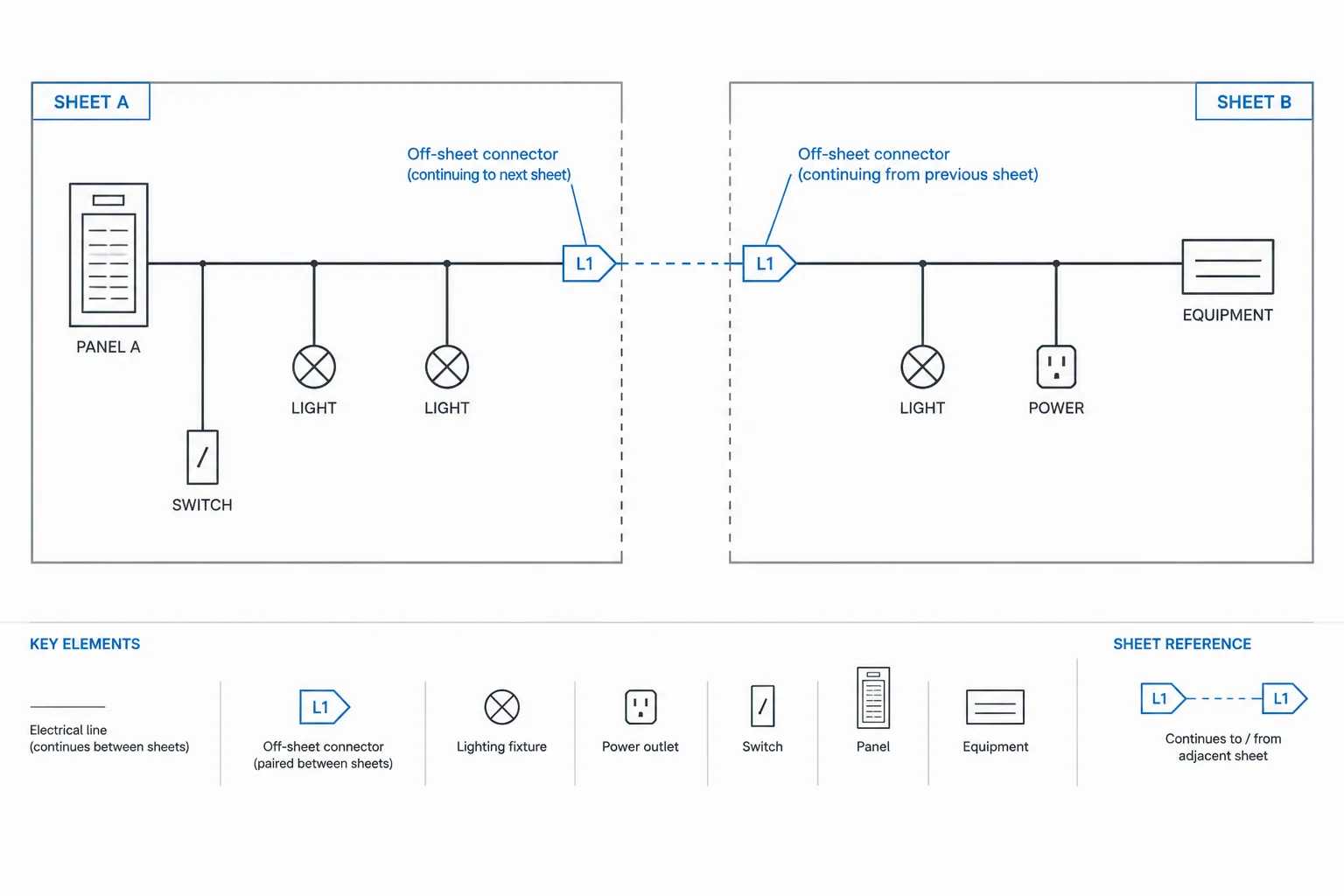
Off-sheet connectors in electrical CAD help readers follow a circuit or signal when its linework cannot remain within one drawing view. Unlike a physical electrical device, the connector is a documentation tool: it identifies an intentional break in the graphics and directs the reader to the corresponding continuation.
The drafting challenge is not simply choosing an arrow or symbol. The connector must remain understandable across sheet organization, equipment tags, drawing zones, schedules, and later revisions. The following guidance explains how to establish that relationship, build usable connector blocks, and review both endpoints as coordinated drawing data.
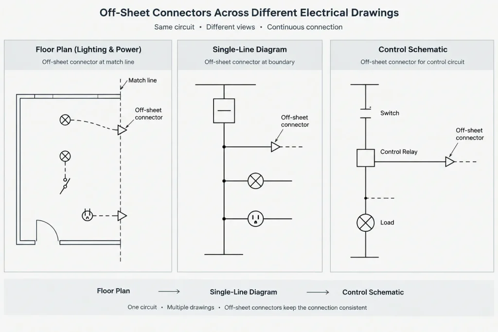
Electrical systems rarely fit neatly on one drawing. A feeder may leave a single-line diagram and continue on another sheet, a control circuit may cross several schematic pages, or a branch circuit may pass through a match line on a large floor plan. Off-sheet connectors provide a controlled way to show that continuity without drawing long, confusing lines across unrelated views.
An off-sheet connector is more than an arrow at the edge of a drawing. It is a coordinated reference that tells the reader where a circuit, conductor, feeder, raceway, or signal continues. Its value depends on consistent symbols, complete reference information, and a reliable relationship between the two ends.
What an Off-Sheet Connector Communicates
A connector should answer two basic questions: what continues, and where can the other end be found? Depending on the drawing type, the answer may include a circuit identifier, feeder tag, cable number, equipment destination, drawing reference, schematic zone, or continuation description.
Common uses include:
- Continuing a feeder between single-line diagram sheets.
- Carrying a circuit across floor-plan match lines.
- Connecting control wiring between schematic pages.
- Showing a cable entering or leaving an equipment diagram.
- Linking a riser segment to a floor plan, detail, or enlarged view.
- Continuing raceway routing where the complete path is divided among plan areas.
The connector does not replace system documentation. Relevant conductor, raceway, cable, or circuit information still needs to appear in the appropriate tags, schedules, notes, or diagrams. The connector primarily manages drawing navigation and continuity.
Choose the Reference Method Before Drafting
Several reference methods can work, but mixing them without a clear hierarchy creates uncertainty. Establish the project method before placing connectors throughout the set.
| Reference method | Typical use | Coordination concern |
|---|---|---|
| Sheet-to-sheet reference | Plans, risers, and one-line diagrams | Sheet identifiers must remain current when the set is reorganized. |
| Drawing-zone reference | Large schematics and dense diagrams | Zone labels must be visible and stable on plotted sheets. |
| Equipment destination | Feeders, cables, and control interconnections | Equipment tags must match plans, schedules, and diagrams. |
| Paired connector identifier | Complex control or wiring diagrams | Each identifier should have a traceable matching endpoint. |
| Match-line reference | Split floor plans and site plans | Both plan areas must show compatible limits and orientation. |
A connector may use more than one type of information. For example, it can identify the destination equipment and give the sheet or zone where the continuation appears. The goal is not to fill the symbol with every available fact, but to provide enough information for an unfamiliar reader to locate the next segment confidently.
Build a Connector Block That Supports Coordination
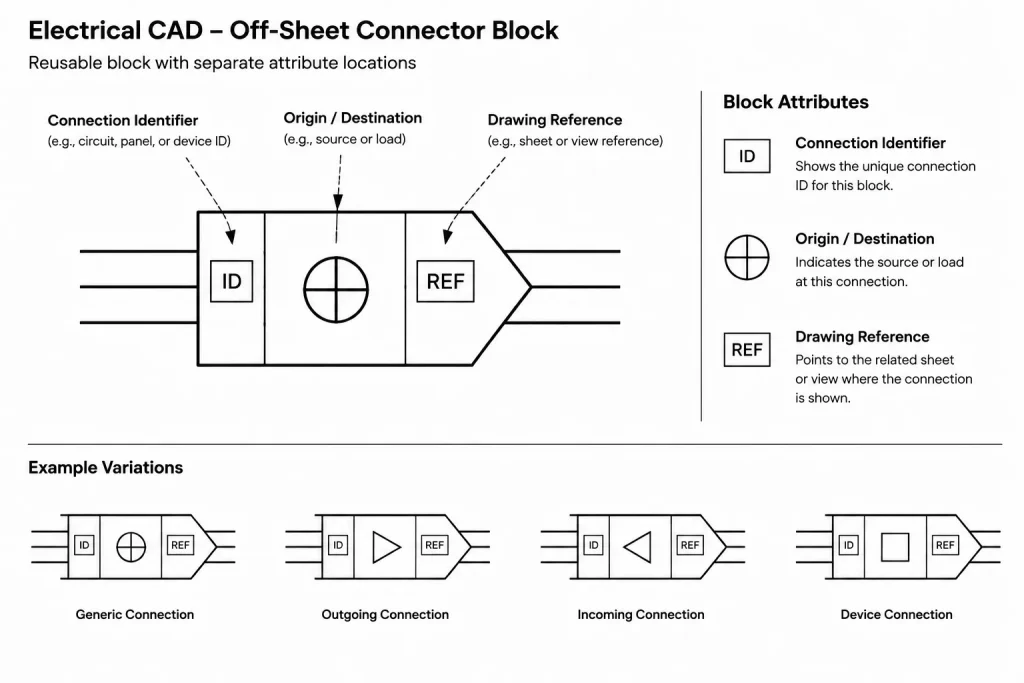
A reusable CAD block helps keep connector graphics and annotation consistent. The geometry should remain simple enough to read at the intended plot scale. Directional symbols may be useful, but direction alone should not carry the meaning.
Useful block components
- A distinct connector outline or arrowhead.
- An attribute for the circuit, feeder, cable, or signal identifier.
- An attribute for the destination or origin.
- An attribute for the continuation sheet, drawing, or zone.
- An optional description field for unusual interfaces.
- A consistent insertion point that aligns with the connected linework.
Keep graphic elements on appropriate layers so linework, text, and optional masking can be controlled separately when required by the office CAD workflow. Avoid burying essential reference text inside a block structure that cannot be searched, extracted, or edited efficiently.
Dynamic behavior or automated fields may improve productivity in some CAD environments, but automation should not be assumed to guarantee coordination. A visible reference can still be wrong if a destination sheet, equipment tag, or drawing zone changes without updating the connector.
Pair the Two Ends Deliberately
Every off-sheet continuation should be reviewed as a pair. At one end, the drawing indicates where the system goes. At the other, the drawing should show where it came from. The wording does not have to be identical, but the references must describe the same connection.
A practical pairing workflow is:
- Assign the system or connection identifier before splitting the linework.
- Place the originating connector and complete its destination fields.
- Place the receiving connector on the continuation drawing.
- Confirm that circuit, feeder, cable, or equipment identifiers agree.
- Trace the route in both directions as part of drawing review.
Do not leave the receiving end implied merely because the destination equipment appears somewhere on the referenced sheet. Dense drawings may contain similar circuits and repeated equipment types. A matching endpoint removes guesswork.
Apply Connectors According to Drawing Type
Floor plans and match lines
On floor plans, connector placement should relate clearly to the point where circuiting or routing leaves the view. Avoid placing the symbol far from the match line unless a leader or other graphic relationship makes the connection unmistakable. If adjacent plan areas overlap, prevent duplicated devices or circuit segments from appearing to represent additional scope.
Single-line and riser diagrams
On a single-line diagram, preserve the source-to-load reading direction established by the diagram. The connector should not make a feeder appear to terminate. Carry the feeder identifier and destination information across the break, and coordinate any associated references with equipment schedules and plan tags.
For risers, distinguish between a graphic continuation caused by sheet layout and a physical transition between floors or systems. An off-sheet break should not accidentally imply a splice, termination, or change in wiring method.
Control schematics
Schematics often require more precise cross-referencing because individual conductors or signals may continue separately. Use stable wire, terminal, device, or signal identifiers according to the project documentation method. Where drawing zones are used, verify that the zone grid remains aligned with the final sheet layout.
Cable and interconnection diagrams
For cable-based drawings, clarify whether the connector represents the complete cable or selected conductors within it. The cable identifier, endpoint equipment, and termination references should agree with the cable schedule and terminal documentation.
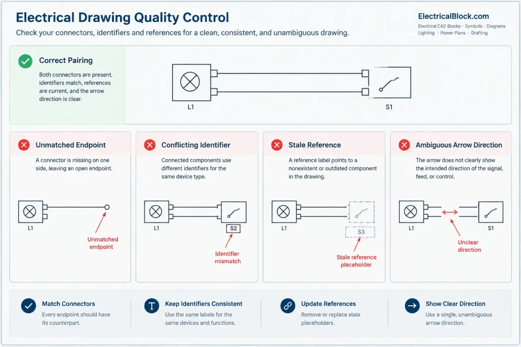
Avoid Common Connector Failures
- Unpaired references: One drawing sends the reader elsewhere, but no receiving connector exists.
- Stale sheet references: Sheets were renamed, inserted, or reordered without updating connector attributes.
- Ambiguous direction: Arrow orientation conflicts with the diagram flow or plan routing.
- Mismatched identifiers: The two ends show different feeder, circuit, cable, or equipment tags.
- Hidden information: Connector text is masked, clipped by a viewport, or plotted at an unreadable size.
- False physical meaning: A drafting break is drawn in a way that resembles a junction, splice, or termination.
- Excessive chaining: Readers must follow several connectors when the information could be presented more directly.
Coordinate Connectors During Revisions
Off-sheet connectors are especially vulnerable during drawing revisions because they depend on information outside the current view. When a sheet is added, removed, renamed, or divided, search the project for references to the affected identifier. Review both visible connector text and block attributes that may not appear in a simple visual scan.
If connector data is extracted into a table, use that table as an audit aid rather than treating it as proof of correctness. A report can reveal unmatched identifiers or unexpected duplicates, but a reviewer still needs to confirm that the paired endpoints represent the intended electrical relationship.
Quality-Control Checklist
- Does every outgoing connector have a receiving endpoint?
- Can the continuation be traced in both directions?
- Do equipment, circuit, feeder, cable, and signal tags match related drawings?
- Are sheet and zone references current?
- Is the connector attached visibly to the correct line or route?
- Does the graphic break avoid implying an unintended electrical connection?
- Are connector symbols included in the legend when their meaning is not self-evident?
- Are attributes readable in plotted and PDF output?
- Have revised, deleted, and relocated continuations been checked across the entire set?
Well-managed off-sheet connectors make a multi-sheet electrical set behave like one coordinated document. By treating each connector as a paired data reference rather than decorative linework, CAD users can preserve continuity across plans, diagrams, schedules, and revisions while making the drawing set easier to navigate and review.
Distinguish Connectors From Other Drawing References
Several electrical drawing tools can point beyond the current view, but they do not communicate the same relationship. Selecting the correct reference type helps prevent a drafting convention from being mistaken for an electrical condition.
- Off-sheet connector: Continues identified electrical linework or related information on another drawing area.
- Match line: Defines the boundary between adjoining plan views and usually coordinates a broader portion of the layout.
- Detail or view reference: Directs the reader to an enlarged or alternate representation rather than continuing the line itself.
- Equipment tag: Identifies an object but does not necessarily explain where connected linework resumes.
- Signal or net label: May establish a logical relationship within a schematic workflow, depending on the CAD platform and project convention.
These methods can work together. For example, linework may stop at a match line while an adjacent connector carries the circuit identifier and continuation reference. The important point is to make the intended navigation path explicit.
Treat Connector Data as Part of the Drawing Set
Connector attributes should be managed with the same care as equipment identifiers, cable tags, and schedule references. A useful office workflow defines who assigns identifiers, who updates destination information, and who checks paired endpoints before drawings are issued.
Consistency is easier to maintain when connector information follows an agreed field order and naming pattern. The displayed text should emphasize what a reader needs for navigation, while editable attributes can support searching and coordination. Avoid relying on block names alone because they may describe symbol geometry without identifying the actual electrical continuation.
Review the Reader’s Path
A final review should follow the document as a reader would. Begin at the source, use the connector to locate the continuation, verify the receiving endpoint, and then trace the same relationship in reverse. This process tests more than matching text; it confirms that the references lead to the intended linework and do not create a false branch, termination, or duplicate route.
When multiple disciplines or CAD files are involved, connector ownership should also be clear. References should not depend on an informal assumption that another drawing team will create or maintain the matching endpoint.
Frequently Asked Questions
Is an off-sheet connector an electrical component?
No. It is primarily a drawing-navigation and continuity symbol. Unless project documentation states otherwise, it should not be interpreted as a splice, terminal, junction, or other physical component.
Should both ends of a continuation have connectors?
Both ends should provide a traceable relationship. A receiving endpoint helps readers confirm that they have found the intended circuit, feeder, cable, raceway, or signal rather than a similar item elsewhere on the drawing.
What information belongs in a connector block?
The useful fields depend on the drawing type and project method. Common information includes the system identifier, origin or destination, and the drawing or zone reference. The displayed content should be sufficient to locate the continuation without overcrowding the symbol.
Can CAD fields or dynamic blocks prevent reference errors?
Automation can reduce repetitive editing, but it does not verify design intent. Connector data still requires review after sheet changes, equipment renaming, file restructuring, or relocation of drawing content.
How are off-sheet connectors different from match lines?
A match line establishes where adjacent plan areas meet. An off-sheet connector identifies the continuation of particular linework or information. A split plan may use both methods when the boundary and the continued electrical route each need to be clear.
Why can matching connector text still be wrong?
Two endpoints may carry identical text while attaching to the wrong linework or referring to an unintended destination. Quality control should therefore check the identifiers, graphic attachment, drawing location, and electrical relationship together.












Leave a Reply
You must be logged in to post a comment.