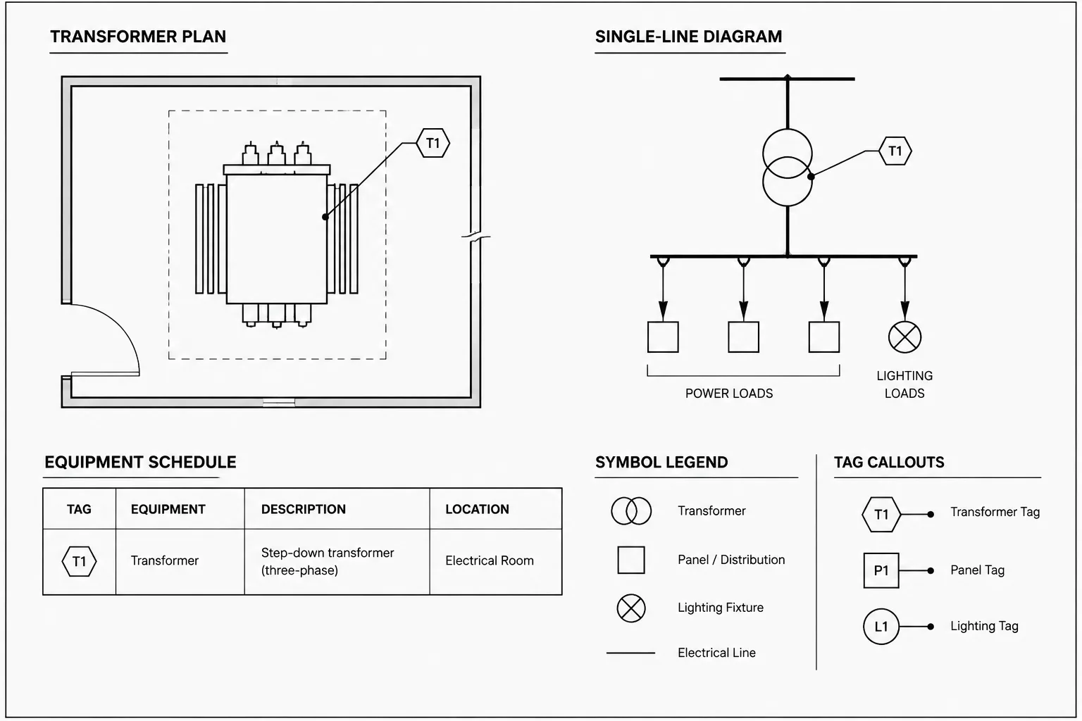
Transformer documentation in CAD depends on coordinated information rather than a single symbol or equipment note. The transformer shown on a plan must remain traceable through the single-line diagram, schedule, installation details, feeder references, and related annotations.
This guide explains how to assign clear responsibilities to each drawing view, manage reusable transformer blocks, and review the resulting documents as one connected record. The emphasis is on drafting consistency and information control; equipment selection, dimensions, clearances, and installation requirements must come from verified project criteria.
A transformer may appear on only a few electrical sheets, but its documentation connects several parts of the drawing set. The floor plan establishes location and access context, the single-line diagram communicates the distribution relationship, the schedule records selected characteristics, and installation details explain coordination requirements that cannot be shown clearly at plan scale.
Good transformer documentation in CAD is not simply a matter of inserting the same block on every sheet. Each drawing view has a different purpose. The drafting task is to keep the equipment identity and design intent consistent while presenting only the information needed for that view.
Start with a single equipment identity
Assign each transformer a unique equipment tag that can be used throughout the project. The same tag should appear on the power plan, single-line diagram, equipment schedule, related details, and any feeder or equipment connection schedules that reference the unit.
A useful tag should identify the equipment without trying to encode every design property into a long abbreviation. Characteristics such as source, voltage relationship, enclosure, winding arrangement, installation type, and accessories are generally easier to manage in a schedule or keyed note. Overloaded tags become difficult to read and are more likely to conflict when a design changes.
Where possible, store the equipment tag as a block attribute or other controlled data field. This supports consistent editing and may simplify schedule extraction. However, automated data should still be checked against the plotted sheets because duplicate tags, blank attributes, and outdated blocks can remain hidden in the model.
Use a view-specific symbol strategy
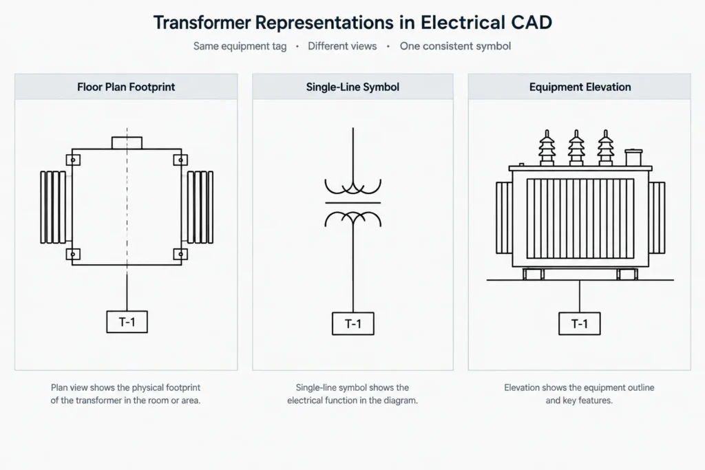
The same transformer should not necessarily use the same graphical block in every drawing context. A floor-plan block represents physical placement, while a one-line symbol represents an electrical relationship. An elevation or coordination detail may use an outline based on verified manufacturer information or a clearly labeled diagrammatic envelope.
| Drawing view | Primary purpose | Typical information |
|---|---|---|
| Electrical plan | Locate and identify equipment | Tag, orientation, connection context, room relationship, working-area coordination where applicable |
| Single-line diagram | Show distribution relationships | Source, transformer tag, upstream and downstream equipment, conductor or raceway references, system relationship |
| Transformer schedule | Collect equipment characteristics | Tag, service description, electrical characteristics, installation description, enclosure information, notes |
| Elevation or section | Explain spatial coordination | Mounting context, adjacent equipment, routing approach, clearances based on verified project criteria |
| Installation detail | Communicate recurring requirements | Support concept, connection arrangement, grounding and bonding references, vibration or environmental coordination when required |
Keep these symbols connected by the equipment tag rather than by forcing one block to serve every purpose. A plan footprint copied into a single-line diagram adds unnecessary geometry, while a schematic symbol placed on a room plan does not communicate the equipment footprint or orientation.
Drafting the transformer on the electrical plan
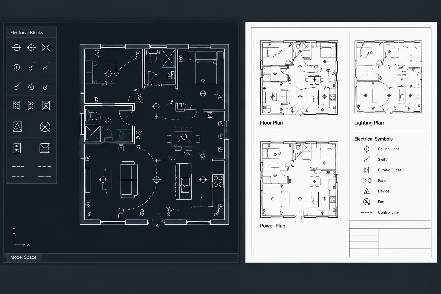
On a floor plan, show the transformer in relation to walls, doors, electrical equipment, structural elements, and major pathways. Use a footprint derived from verified project information when the drawing is intended for physical coordination. A generic block can be useful during early design, but it should be clearly treated as diagrammatic until the selected equipment has been reviewed.
The plan should make the equipment tag easy to find without covering the footprint or nearby connection information. Use a leader when the room is congested, and place the tag according to the project’s normal annotation convention. If the transformer is wall-mounted, suspended, outdoors, or otherwise installed in a way that is not obvious in plan, add a concise note or detail reference.
Show coordination rather than unsupported precision
A CAD block can look exact even when its dimensions are only placeholders. Avoid creating false confidence with an unverified enclosure outline. If exact dimensions are not available, use a controlled generic representation and identify the need for final coordination in the appropriate project documentation.
Also consider how feeders approach and leave the transformer. The plan does not need to depict every bend, but it should avoid implying a routing path that conflicts with doors, access zones, ceiling systems, or other equipment. Coordinate detailed raceway routing on the sheets where that information belongs.
Coordinating the single-line diagram
The transformer symbol on a single-line diagram should communicate the source-to-load relationship clearly. Place the equipment tag next to the symbol and organize the diagram so that upstream and downstream connections can be followed without crossing unrelated circuits.
Do not rely on the shape of a generic transformer symbol to communicate all electrical characteristics. Winding configuration, grounding arrangement, system designation, and similar information should be stated using the project’s established notation, schedule fields, or keyed notes. Symbol conventions vary, and a familiar-looking graphic can be misread if its meaning is not defined in the legend.
Check that connected equipment names and feeder references agree across the one-line, plans, schedules, and panel documentation. A transformer renamed during design can leave behind several mismatched references. Searching the CAD files for the previous tag is a practical way to find stale labels before issue.
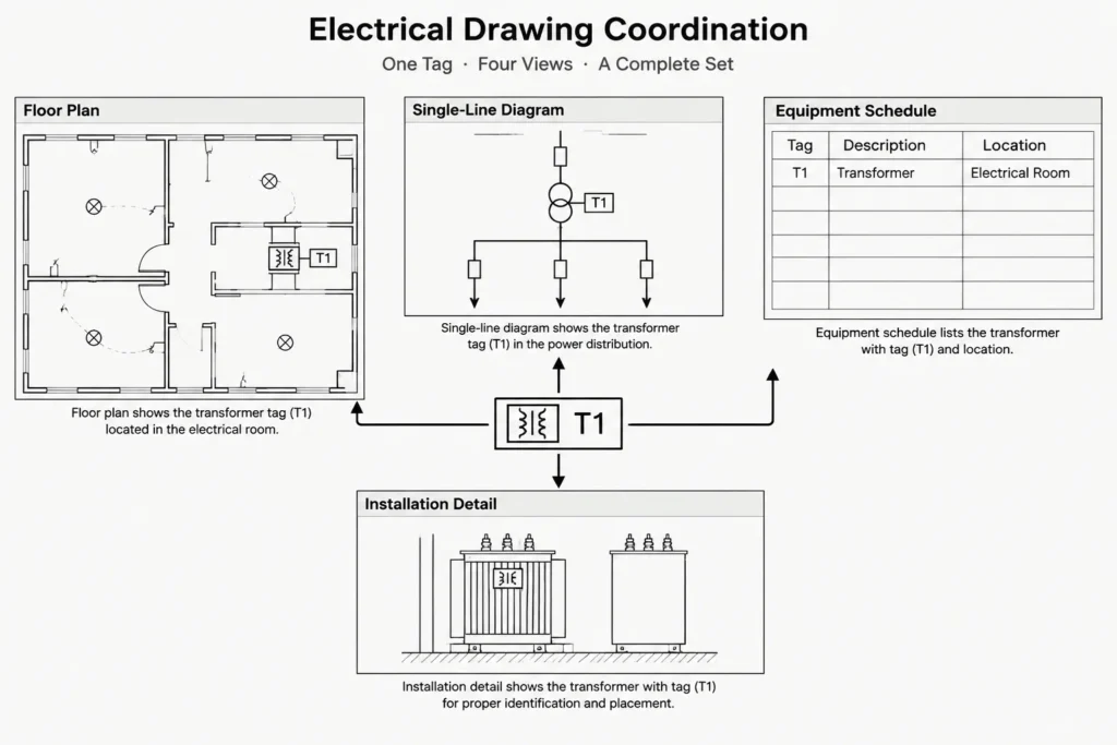
Building a useful transformer schedule
A transformer schedule should centralize information that would otherwise be repeated beside multiple symbols. The fields should reflect the project’s documentation needs rather than copying every available product characteristic.
Possible schedule fields include:
- Equipment tag and service description
- Location or room reference
- Source equipment and served equipment
- Primary and secondary system descriptions
- Capacity or design designation based on verified project data
- Phase or configuration information where relevant
- Installation and enclosure descriptions
- Grounding, bonding, monitoring, or accessory notes where required
- Related detail or specification references
Separate data into distinct columns instead of combining several properties in one note cell. Structured fields are easier to review, sort, and update. Reserve general notes for requirements that apply to several transformers, and use item-specific notes only where an individual unit differs.
Use details to explain installation intent
A typical detail can clarify support, routing, connection, and coordination concepts without crowding the floor plan. It should not imply that one arrangement applies universally. Identify the conditions covered by the detail and provide separate details when wall-mounted, floor-mounted, suspended, indoor, or outdoor conditions require meaningfully different documentation.
Keep proprietary or product-specific geometry out of a generic detail unless the project has verified the selected equipment. When a manufacturer drawing is used as a coordination reference, redraw or reference only the information needed for the project and track its source internally. Do not treat a downloaded CAD block as evidence of compliance, fit, or approval.
Organize layers and blocks for reliable editing
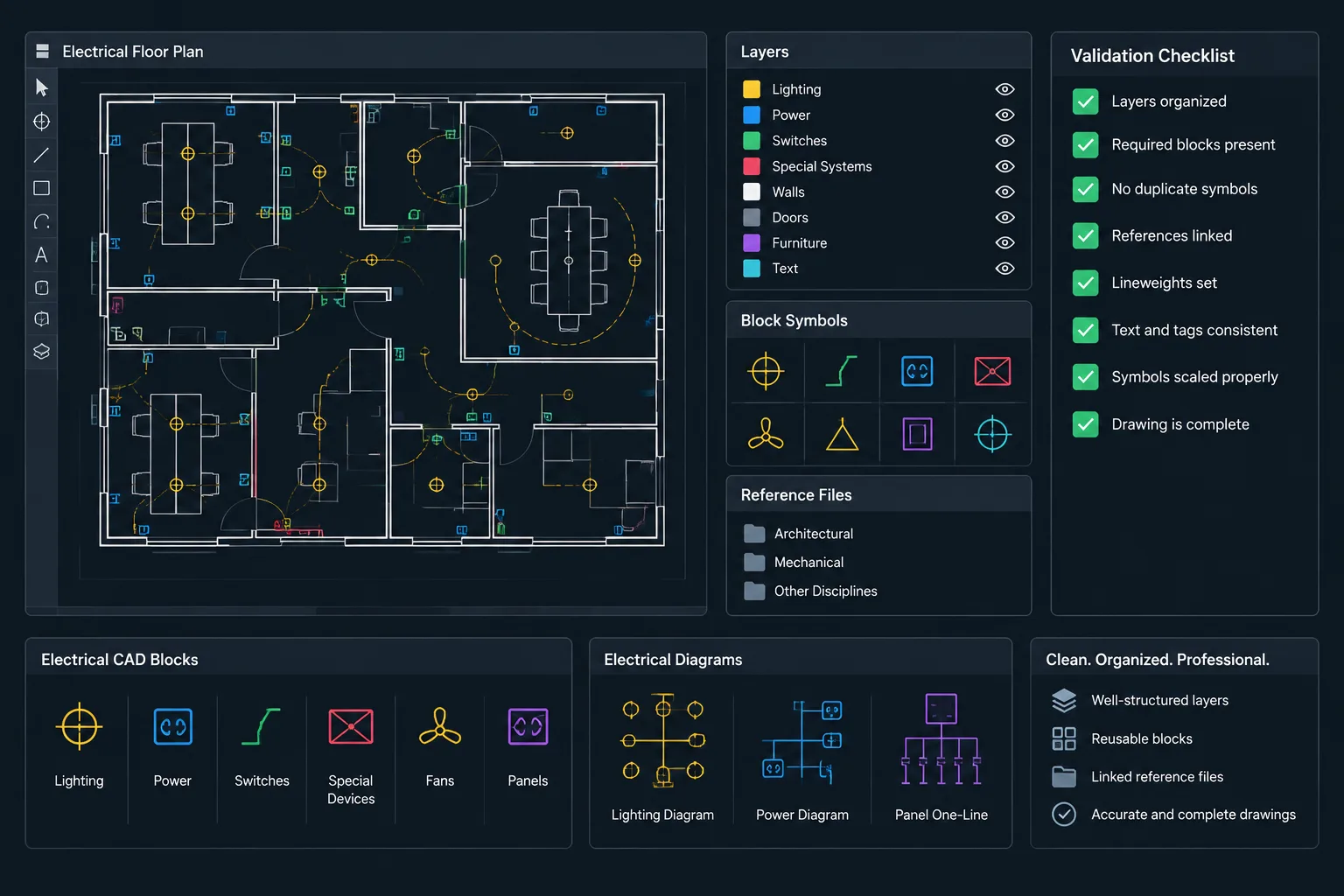
Place transformer footprints, tags, connection lines, clearance graphics, and detail annotations on layers that match the office or project CAD standard. Separating these elements allows the plotted hierarchy to be controlled without editing individual objects.
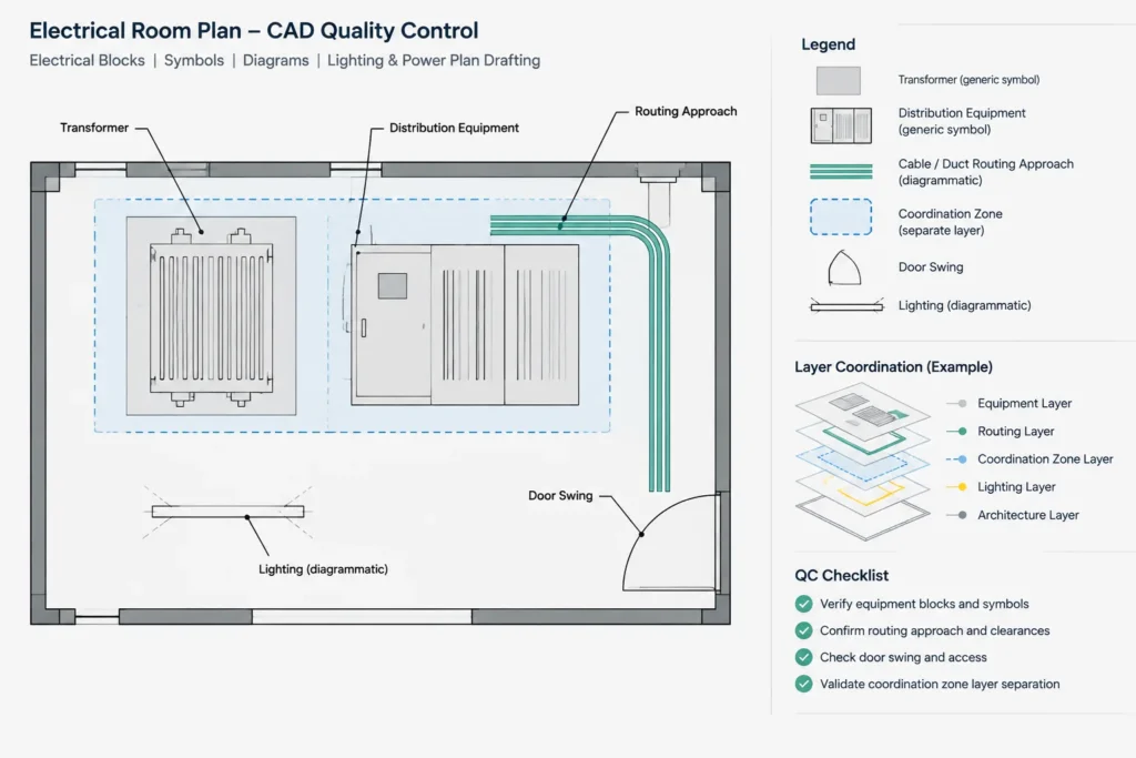
A practical block structure may include a clean equipment outline, an insertion point tied to a meaningful physical reference, and attributes for the tag and optional description. Avoid placing fixed feeder names, room numbers, or ratings inside reusable geometry. Those values change from project to project and should remain editable.
If a block includes a clearance or maintenance zone, put that geometry on a dedicated layer or controllable block component. Such graphics are valuable for coordination but can overwhelm a construction plan if they cannot be managed separately. Any clearance shown must come from verified project criteria rather than a generic library assumption.
Perform a cross-sheet transformer check
Before issuing the drawing set, review transformers as a connected documentation group rather than checking each sheet independently.
- Confirm that every plan tag has a matching schedule and one-line entry.
- Verify that no duplicate equipment tags exist.
- Compare source and load descriptions across diagrams and schedules.
- Check that plan locations agree with architectural room names and current backgrounds.
- Review footprint dimensions and orientation against verified equipment information.
- Confirm that detail references point to existing details and sheets.
- Look for obsolete tags in notes, feeder schedules, panel schedules, and callouts.
- Plot the relevant sheets and check symbol, text, and lineweight readability.
This cross-sheet review catches a common documentation problem: each individual view may look correct while the views disagree with one another.
Treat the CAD library as a starting point
A well-maintained transformer block library improves drafting speed and graphical consistency, but it does not replace project-specific design review. Library content should distinguish between schematic symbols, generic plan footprints, and verified equipment outlines. Include a clear description of each block’s intended drawing context so users do not mistake a diagrammatic symbol for a coordinated physical model.
The strongest transformer documentation uses CAD blocks as controlled communication tools. Consistent tags connect the drawings, schedules hold structured information, diagrams explain system relationships, and details address installation context. When these elements are coordinated deliberately, reviewers can follow the transformer from its source to its physical location and downstream distribution without relying on assumptions.
Establish an information hierarchy
Cross-sheet consistency is easier to maintain when the project team defines where each type of information is controlled. The equipment tag may provide the common identifier, while the schedule manages selected characteristics, the single-line diagram establishes distribution relationships, and the plan controls location. Details can then explain installation or coordination conditions without becoming a second equipment schedule.
This hierarchy does not mean that information appears in only one place. Important references may need to be repeated for drawing clarity. It does mean that duplicated information should have an identified source so discrepancies can be resolved systematically rather than by guessing which sheet is current.
Manage transformer changes as linked revisions
A transformer revision often affects more than the object being edited. A change in location can alter plan coordination and detail references. A revised source or served load can affect the one-line diagram, feeder identification, schedules, and equipment callouts. A tag change can leave obsolete text throughout the drawing set.
Use a revision workflow that treats the transformer as a linked documentation item. Record the affected views, update controlled fields, search for previous identifiers, and compare plotted output. Where data is extracted from block attributes, confirm that manual notes and externally referenced drawings have also been reviewed.
Distinguish design status from graphical completeness
Highly finished CAD graphics can make preliminary information appear verified. Use notes, layer controls, block names, or internal drafting status fields to distinguish a generic footprint from an equipment outline based on reviewed information. Remove or revise temporary indicators when the design status changes so they do not become permanent but misleading annotations.
The final quality check should evaluate both graphical communication and data agreement. A clean plan symbol is not sufficient if the tag is missing from the schedule, and a complete schedule is not sufficient if its corresponding one-line connection is unclear.
Frequently Asked Questions
Should the same transformer block be used on plans and single-line diagrams?
Not necessarily. A plan block communicates physical placement and orientation, while a single-line symbol communicates an electrical relationship. Separate view-specific blocks can be connected through the same equipment tag.
Where should transformer characteristics be documented?
Use structured schedule fields, established diagram notation, and keyed notes according to the project’s documentation system. Avoid placing changing project data permanently inside reusable block geometry.
Can a generic transformer footprint be used for coordination?
A generic footprint can support early drafting when it is clearly identified as diagrammatic. Physical coordination should rely on verified project information, and the drawing should not imply unsupported dimensional accuracy.
How can duplicate or obsolete transformer tags be found?
Search the CAD files for current and previous identifiers, review block attributes, and compare plans, one-lines, schedules, details, feeder references, and callouts. A plotted cross-sheet review can reveal discrepancies that are difficult to notice in the model.
What information belongs in a reusable transformer CAD block?
A reusable block can include clean geometry, a meaningful insertion point, and editable attributes for identification or description. Fixed room names, feeder names, ratings, and other project-specific data should remain separately editable.
Which document should control when transformer information conflicts?
The project team should define an information hierarchy and identify the controlled source for each data type. Conflicts should be resolved against verified design information and then corrected everywhere the affected information appears.






Leave a Reply
You must be logged in to post a comment.