
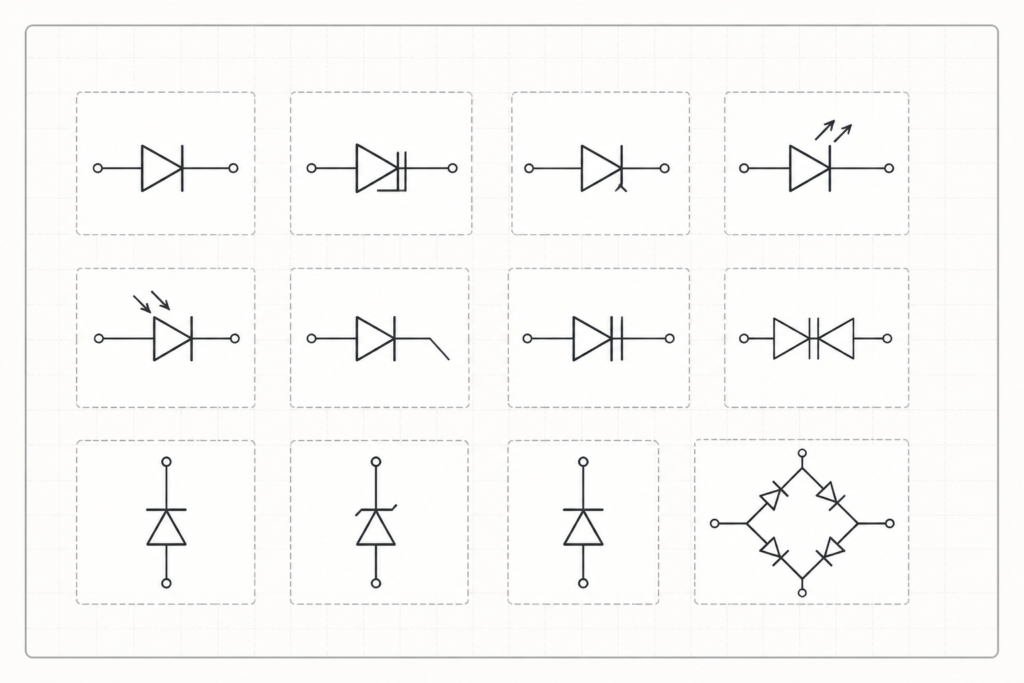
This diode sign symbols DWG provides a practical CAD reference for representing common diode types in electrical and electronic schematic drawings. The block includes standard diode, Zener diode, LED, and other diode symbols for use in organized circuit documentation.
Use the file alongside your electrical legends, schematic symbol libraries, and drawing templates to maintain consistent component notation. It is intended for drafting and documentation support; symbol selection and circuit interpretation should always be checked against the project requirements and applicable engineering review process.
Download a high-quality DWG file featuring various diode sign symbols optimized for electrical and electronic schematic designs. This CAD block includes standard diode, Zener diode, LED, and other essential diode symbols, making it ideal for engineers, architects, and designers working on circuit diagrams. The file is fully compatible with AutoCAD and other popular CAD software, ensuring seamless integration into your projects. Use these diode sign symbols to accurately represent electronic components in your technical drawings and enhance the clarity of your electrical schematics. Perfect for both educational and professional applications.
Please log in or register to download this file.
What the diode symbols DWG contains
The downloadable CAD block groups several diode-related symbols in a format that can be incorporated into AutoCAD and other compatible CAD software. This makes it useful when preparing circuit diagrams, equipment documentation, control schematics, or educational drawings that need recognizable electronic component symbols.
How to use the block in electrical drafting
- Review the symbol set first: Identify the required diode symbol before placing it in a schematic or electrical legend.
- Keep symbols consistent: Use the same graphical convention throughout a drawing set so readers can interpret circuit documentation efficiently.
- Coordinate with surrounding documentation: Relate diode symbols to component tags, connection lines, terminal information, and notes used elsewhere in the project.
- Preserve drawing clarity: Avoid crowded placements and verify that symbol orientation, labels, and connection points remain readable at the intended print or screen scale.
- Confirm project conventions: A CAD block is a drafting resource, not a substitute for the project electrical legend, design criteria, or engineering review.
Related electrical CAD references
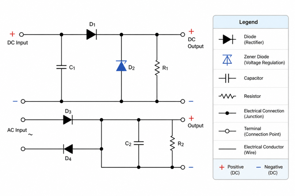
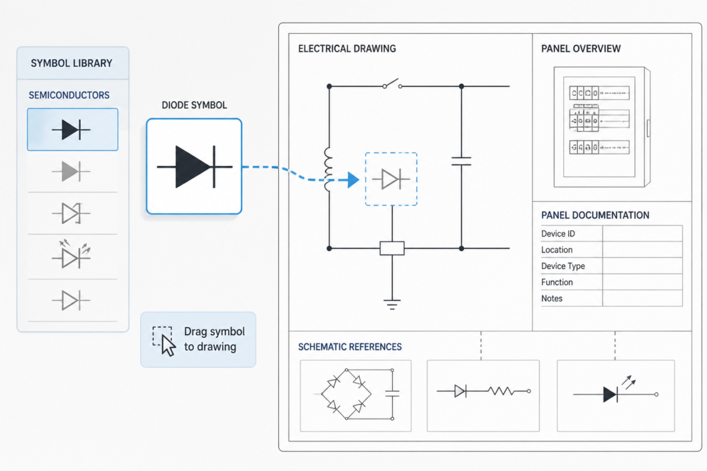
Diode symbols commonly appear with broader schematic-symbol libraries, electrical legends, single-line diagram concepts, panel documentation, and equipment layouts. Connecting this block with those reference materials helps create a more consistent workflow from component-level diagrams to coordinated electrical drawing packages. It can also support CAD standards work involving reusable blocks, layer organization, and annotation practices.
Before issuing a drawing
Check the inserted symbol against the source block, the project legend, and the intended circuit meaning. Confirm that the drawing remains legible after plotting or export, and have the completed electrical documentation reviewed by the responsible designer or engineer. Do not use a schematic symbol library as instructions for working on energized equipment.
FAQ
What is included in this diode sign symbols DWG?
The file includes standard diode, Zener diode, LED, and other diode symbols intended for electrical and electronic schematic drafting.
Can the DWG be used with AutoCAD?
Yes. The source description identifies the file as compatible with AutoCAD and other popular CAD software. Confirm compatibility with the specific software environment used for your project.
Who can use this CAD block?
Engineers, architects, designers, students, and CAD technicians can use the symbols as drafting resources for circuit diagrams and related technical drawings.
Does the block determine which diode a circuit requires?
No. The block provides graphical symbols only. Component selection, circuit function, ratings, and design compliance require project-specific electrical engineering review.
How should the symbols be checked before issue?
Compare the selected symbol with the project electrical legend and drawing conventions, then verify its orientation, labeling, connection points, and readability in the completed schematic.












Leave a Reply
You must be logged in to post a comment.