
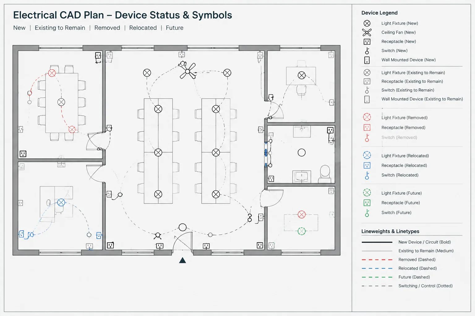
Circuit diagram symbols CAD blocks help electrical drafters build clear, consistent schematics without redrawing common graphical elements. The accompanying DWG resource is intended for engineers, students, and CAD professionals who need reusable symbols for electrical design documentation.
Use the existing download as a drafting reference for circuit diagrams, control panels, wiring documentation, and related electrical layouts. Before issuing a drawing, review each symbol against the project’s drafting conventions, legend, and engineering requirements.
Discover a comprehensive collection of **Circuit Diagram Symbols** available in DWG format, perfect for engineers, students, and professionals working on electrical design projects. This CAD Block file contains a wide array of standardized symbols used in circuit diagrams, ensuring accuracy and efficiency in your schematics. Easily compatible with AutoCAD and other leading CAD software, these symbols streamline the creation of electrical layouts, control panels, and wiring diagrams. Ideal for both educational and professional applications, this DWG file is meticulously organized, making it a valuable resource for any electrical CAD project. Download now to enhance your circuit design workflow.
Please log in or register to download this file.
How circuit diagram symbols support electrical drafting
A circuit symbol is a visual shorthand for an electrical component, connection, or function. CAD blocks turn that shorthand into reusable drawing content that can be inserted, arranged, and edited within a DWG workflow. Consistent symbols make a schematic easier to read and help different members of a design team interpret the same drawing language.

Symbols, layouts, and drawing context
Symbols used in a schematic do not automatically describe the physical location, installation method, or complete technical characteristics of equipment. A circuit diagram communicates relationships and functions, while a plan, panel drawing, wiring diagram, or single-line diagram may provide a different view of the same design. Use the appropriate symbol set and drawing context for the document being prepared.
Practical workflow for using the DWG blocks
- Review the available blocks before beginning a new schematic or electrical layout.
- Place symbols using a consistent orientation, alignment method, and annotation style.
- Keep symbols legible at the intended drawing scale and avoid unnecessary overlaps.
- Coordinate symbol use with the electrical legend and project naming conventions.
- Check connections, references, and notes before sharing or issuing the drawing.
Related electrical CAD documentation
Circuit symbols commonly work alongside electrical legends, panel documentation, distribution diagrams, lighting and power plans, cable and conduit drafting, and equipment layouts. Organizing these topics together gives a project team a clearer path from schematic intent to documented installation information, while keeping the symbol library itself focused on reusable graphical content.

Important review note
CAD blocks improve drafting efficiency, but they do not replace design review or engineering verification. Confirm that the selected symbol communicates the intended function and that the completed drawing agrees with the project requirements before relying on it for construction, coordination, or fabrication.
Frequently asked questions
What are circuit diagram symbols CAD blocks?
They are reusable DWG drawing elements that represent electrical components, connections, or functions in circuit diagrams and related documentation.
Can the DWG file be used with AutoCAD?
The resource is provided in DWG format and is described as compatible with AutoCAD and other leading CAD software. Confirm compatibility with the specific CAD application and version used on your project.

Are these symbols suitable for every electrical drawing?
Not automatically. Symbol conventions can vary by project, discipline, and document type, so review the blocks against the drawing legend and applicable project requirements.
Do CAD symbols verify an electrical design?
No. Symbols communicate design intent and drafting information; they do not replace engineering calculations, coordination, inspection, or approval.











Leave a Reply
You must be logged in to post a comment.