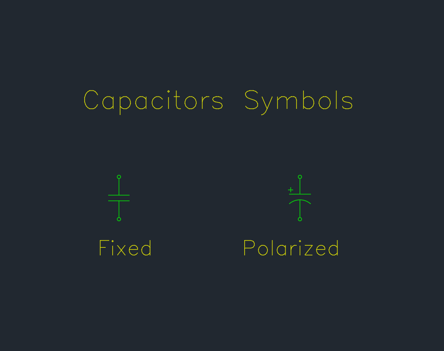
Capacitor symbols are essential building blocks for readable schematics, circuit diagrams, and electrical documentation. This DWG collection brings several common capacitor symbol types together for use in AutoCAD and compatible CAD software.
Use the block as a drafting reference when preparing electrical legends, schematic layouts, PCB documentation, or related design drawings. Before issuing a drawing, compare the selected symbol with the project legend and the conventions required by the responsible engineering team.
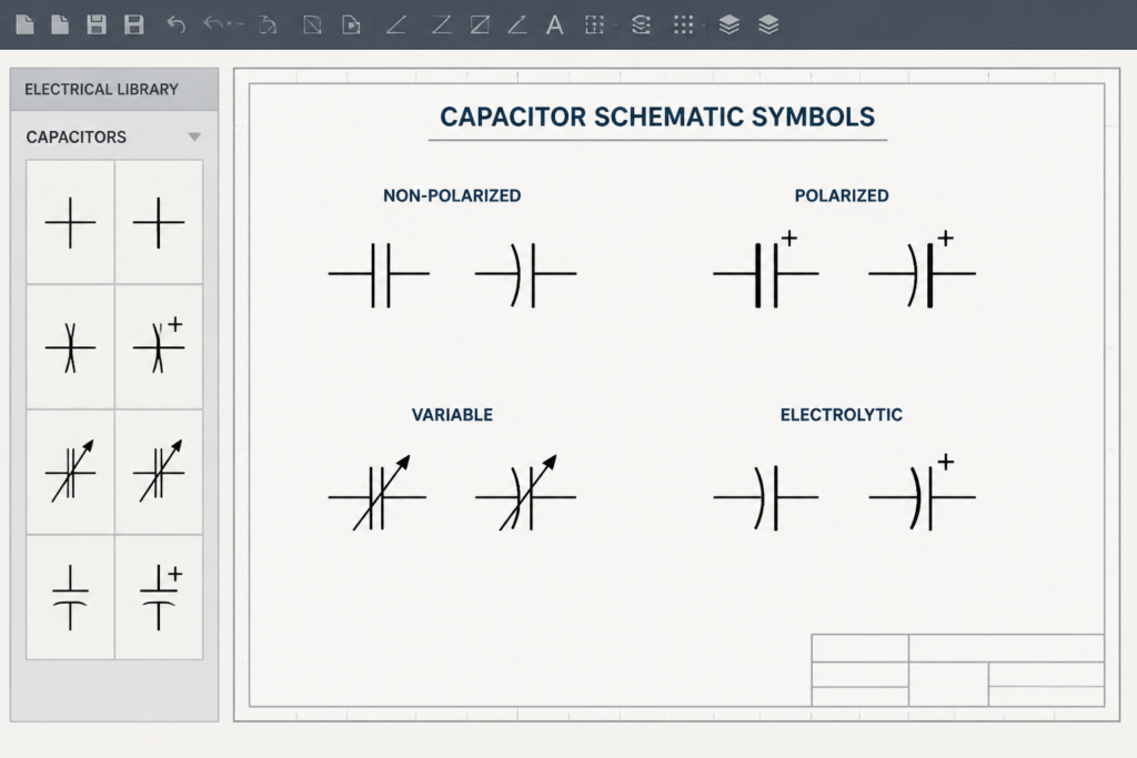
Discover a comprehensive collection of Capacitors Symbols available in DWG format, perfect for electrical and electronic CAD projects. This detailed CAD Block file features a wide variety of capacitor symbols, including polarized, non-polarized, variable, and electrolytic types. Ideal for engineers, architects, and designers, these symbols streamline schematic design and documentation in electrical layouts. Fully compatible with AutoCAD and other popular CAD software, the DWG file ensures seamless integration into your projects. Enhance your circuit diagrams, PCB layouts, and electrical plans with these precise, industry-standard Capacitors Symbols. Download and elevate your CAD workflow today!
Please log in or register to download this file.
What is included in the capacitor symbols DWG?
The CAD block collection includes symbols for polarized, non-polarized, variable, and electrolytic capacitors. Keeping these variations available in one drawing resource can help drafters select a representation that matches the component or documentation context.
How capacitor symbols support CAD documentation
Clear symbols make circuit intent easier to review and help maintain consistency across schematics and electrical plans. A reusable DWG block can also reduce repetitive drafting work when symbols are placed in a drawing set, legend, or design library.
- Polarized symbols: Use when the documented component has a defined polarity that must be represented.
- Non-polarized symbols: Use for capacitor representations where polarity is not shown in the symbol.
- Variable symbols: Use when the drawing needs to identify an adjustable capacitance function.
- Electrolytic symbols: Use when the documentation calls for the electrolytic capacitor representation included in the block collection.
Drafting checks before using the block
Confirm that the symbol matches the component schedule, schematic intent, and project legend. Check orientation, visible identification marks, layer behavior, and annotation before copying the block into a production drawing. Coordinate capacitor symbols with related electrical CAD content such as schematic symbols, lighting and power plans, panel documentation, and single-line diagram concepts.
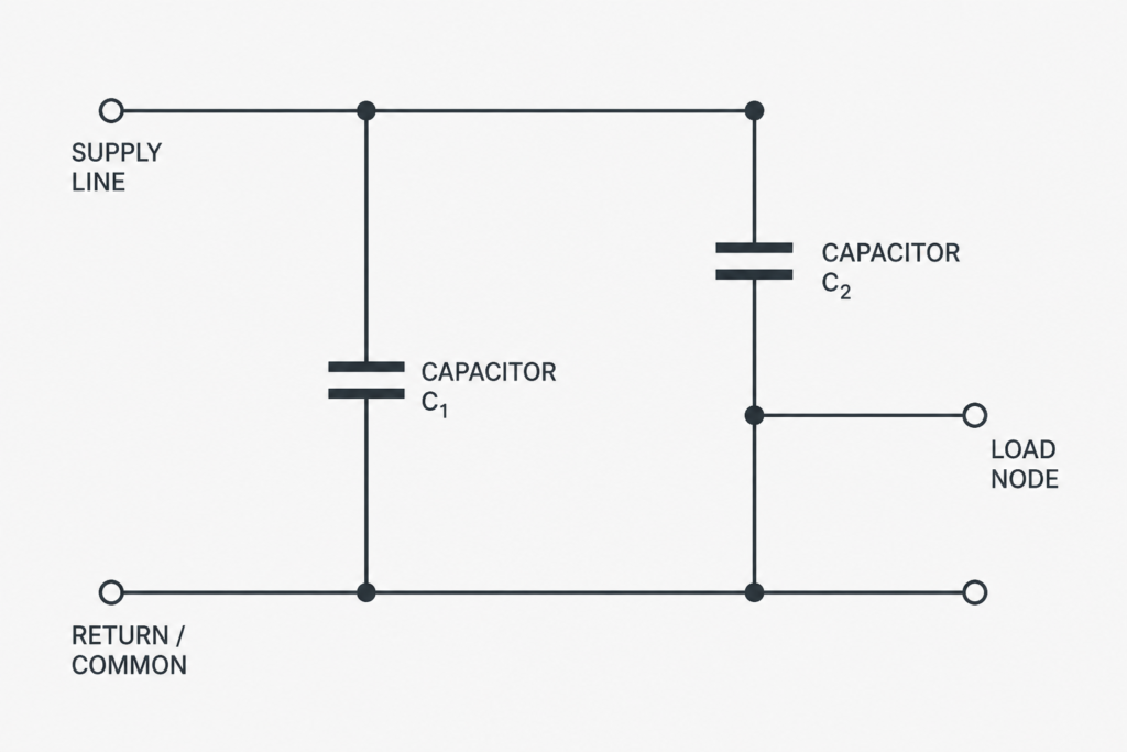
This download is a drafting resource, not a substitute for component selection, circuit analysis, or engineering review. Do not use a drawing symbol alone to determine installation requirements or safe work procedures.
Frequently asked questions
What capacitor types are represented in this DWG?
The collection includes polarized, non-polarized, variable, and electrolytic capacitor symbols.
Can I use the file in AutoCAD?
Yes. The source content identifies the file as a DWG compatible with AutoCAD and other popular CAD software.
Where can capacitor symbols be used?
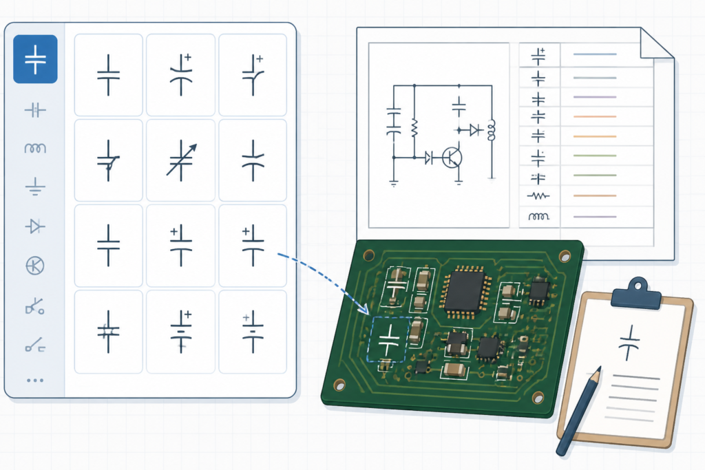
They can support schematic design, circuit diagrams, PCB layouts, electrical plans, legends, and other technical documentation where capacitor components must be represented.
Should the symbols be checked before issuing a drawing?
Yes. Compare each symbol with the project legend, component information, and the conventions established by the responsible engineering team before releasing the drawing.












Leave a Reply
You must be logged in to post a comment.