
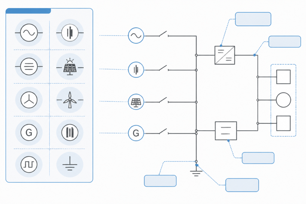
Power supply symbols DWG files help drafters represent electrical power sources consistently across schematics, single-line diagrams, and plan drawings. A well-organized symbol collection can make drawing production faster while keeping the visual language of a project easier to review.
This resource provides a ready-to-use CAD block collection for electrical engineering and architectural documentation. Use the symbols as drafting references, then confirm that their meaning, orientation, layer behavior, and graphic style match the project’s legend and documentation requirements.
Download a high-quality DWG file featuring detailed Power Supply Symbols, perfect for electrical engineering and architectural projects. This CAD Block includes a comprehensive collection of standardized power supply icons commonly used in schematic diagrams and electrical layouts. Ideal for professionals and students, these symbols streamline your design process and ensure compliance with industry standards. The file is fully compatible with AutoCAD and other leading CAD software, allowing for easy integration into your project drawings. Enhance your electrical plans with accurate, ready-to-use Power Supply Symbols for efficient and precise design work.
Please log in or register to download this file.
How power supply symbols support electrical drafting
Power supply symbols communicate where electrical energy originates, enters, or is distributed within a drawing. Their meaning depends on the drawing type and the surrounding documentation, so a symbol should be read together with circuit identifiers, notes, connection lines, and the project legend.
Common drawing applications
- Schematic diagrams: show conceptual relationships between a source, protective devices, controls, and connected equipment.
- Single-line diagrams: provide a simplified view of distribution paths and major electrical equipment.
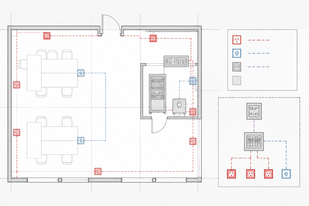
- Power plans: help coordinate the location and documentation of electrical devices and connection points.
- Electrical legends: define the graphic meaning of symbols used throughout a drawing set.
Practical CAD workflow
Before inserting a block, review the drawing’s units, insertion behavior, layer structure, lineweight conventions, and annotation style. Place symbols consistently and avoid using a block as a substitute for circuit information that belongs in notes, schedules, or a diagram.
After placement, check the symbol at the intended drawing scale and in plotted output. Confirm that connection points align with related graphics, that attributes remain readable, and that duplicated symbols do not create ambiguous or conflicting interpretations.
Reference checklist for power supply symbol blocks
- Confirm the symbol’s intended meaning from the project legend.
- Check orientation and connection alignment before copying it through a drawing.
- Keep symbols on the appropriate drawing layers and avoid unnecessary exploded geometry.
- Coordinate symbol use with panel, equipment, lighting, and power documentation.
- Have the completed design reviewed by the responsible electrical professional.
Related electrical CAD topics
Power supply symbols are most useful when coordinated with electrical legends, panel documentation, distribution diagrams, equipment layouts, cable and conduit drafting, and other schematic symbols. Reviewing these topics together helps maintain consistent graphics across the complete drawing set.
Frequently asked questions
What is included in a power supply symbols DWG file?
The supplied CAD block contains a collection of power supply icons intended for use in schematic diagrams and electrical layouts. Review the file after opening it to confirm the available symbols and their graphic conventions.
Can these symbols be used in AutoCAD?
Yes. The source content identifies the file as compatible with AutoCAD and other leading CAD software. Compatibility should still be checked in the specific software version and project template being used.
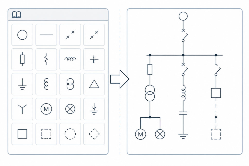
Are power supply symbols the same in every drawing set?
No. Symbol meaning and presentation can vary by project convention, discipline, and documentation method. Always compare the block with the active electrical legend and project standards before issuing a drawing.
Should a symbol block be edited before use?
It may need layer, color, lineweight, orientation, or annotation adjustments to match the project template. Preserve the intended meaning and avoid edits that could make the symbol unclear.
Can these blocks replace electrical design review?
No. CAD blocks support graphic documentation, but they do not establish circuit design, equipment suitability, code compliance, or installation requirements. The responsible electrical professional should review the completed documentation.












Leave a Reply
You must be logged in to post a comment.