
Relay coil symbols represent the operating element of a relay in an electrical schematic or control drawing. The DWG resource on this page can help drafters create a consistent graphical language for relay logic, control circuits, and related documentation.
Before incorporating any symbol into a drawing set, compare its appearance with the symbol convention, layer structure, and tagging method established for the project. A relay coil graphic communicates more effectively when its associated contacts can be identified through clear device labels and cross-references.
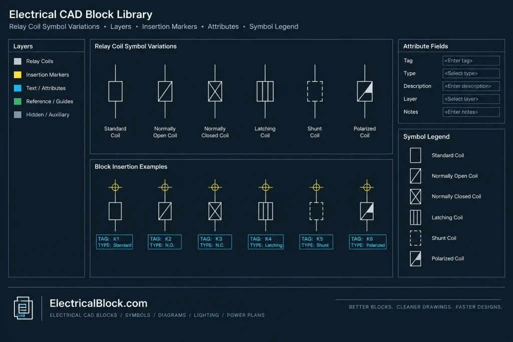
Discover high-quality Relay Coils Symbols in DWG format, perfect for your next electrical CAD project. This CAD Block file features detailed and professionally designed relay coil symbols, widely used in electrical schematic diagrams and control panel layouts. Ideal for engineers and designers, these symbols enhance clarity and standardization in your drawings. Fully compatible with AutoCAD and other leading CAD software, you can easily integrate these relay coil symbols into your projects. Simplify your workflow and ensure accuracy with this essential DWG file for relay coil representation.
Please log in or register to download this file.
Understanding Relay Coil Symbols
A relay coil symbol identifies the portion of a relay that responds to a control signal and operates associated contacts. In a schematic, the coil and contacts may appear in different parts of the drawing. Matching device tags or cross-reference notes allow readers to understand that the separated symbols belong to the same relay.
The coil symbol is a functional schematic representation rather than a physical equipment outline. It should not be treated as a mounting footprint, enclosure layout, or manufacturer-specific component drawing unless the source file explicitly provides that information.

Recommended CAD Review Before Use
- Symbol convention: Confirm that the graphic matches the drafting convention used throughout the drawing package.
- Block definition: Check the block name, insertion point, orientation, and behavior before placing repeated instances.
- Layers: Move geometry, labels, and annotations to the appropriate project layers when necessary.
- Attributes: Review any editable fields intended for relay tags, descriptions, locations, or cross-references.
- Text appearance: Confirm that text style, size, and alignment remain readable at the plotted drawing scale.
- Contact coordination: Use consistent identifiers for the relay coil and every associated contact shown elsewhere in the schematic.
Using the Block in a Control Schematic
Insert the relay coil block into a working copy of the drawing and inspect it before adding it to a shared symbol library. Avoid exploding the block unless project standards require separate geometry, because maintaining a block definition can make repeated symbols easier to update consistently.
Place the symbol so that circuit flow, wire connections, and adjacent annotations remain clear. The relay identifier should be visually associated with the coil without obscuring conductors or terminal information. If contacts are located on another sheet or drawing zone, add the cross-reference information used by the project documentation system.
Related Drawing Topics
This resource connects naturally with electrical schematic symbols, relay contact symbols, control wiring diagrams, terminal symbols, panel drawing concepts, electrical legends, CAD layers, and block-attribute workflows. Reviewing those topics together can improve consistency between the symbol library, schematic sheets, and drawing index.
Important Documentation Limit
A generic relay coil symbol does not establish a relay’s electrical characteristics, terminal arrangement, operating behavior, or installation requirements. Verify those details against approved project documentation and manufacturer information. The DWG should be treated as a drafting resource, not as a substitute for engineering review.
Relay Coil Symbol FAQ
What does a relay coil symbol show?
It identifies the operating element of a relay within a schematic. Associated relay contacts may be drawn separately and connected logically through matching tags or cross-references.
Does the coil symbol include the relay contacts?
Not necessarily. Many control drawings place contacts where they function in the circuit rather than beside the coil. Clear device identification is therefore essential.
Can this DWG be added to a CAD symbol library?
Yes, after reviewing the block name, layers, insertion point, attributes, and graphic convention. Library naming should follow the established documentation practice for the project or organization.

Is a schematic symbol the same as a physical relay footprint?
No. A schematic symbol explains circuit function, while a footprint or equipment outline represents physical form and placement. Do not infer mounting or dimensional information from a generic coil symbol.
Why should relay coils and contacts use matching identifiers?
Matching identifiers help readers trace the relationship between the operating coil and contacts located elsewhere in the drawing set. They also support drawing checks and future revisions.
What should be checked after inserting the block?
Review orientation, connection alignment, layer assignment, text readability, device labeling, and cross-references. Also confirm that the symbol remains consistent with the rest of the schematic.












Leave a Reply
You must be logged in to post a comment.