
Schematic Wiring Symbols DWG files help electrical drafters communicate circuit intent clearly across plans, diagrams, and documentation sets. A consistent symbol library can make drawings easier to read, coordinate, and review while reducing repetitive drafting work.
Use the source file below as a practical CAD reference when developing wiring diagrams, electrical legends, and related drawing content in AutoCAD or compatible software. Confirm the meaning and appearance of each symbol against the project legend and applicable design requirements before issuing a drawing.
Discover a comprehensive collection of Schematic Wiring Symbols in this high-quality DWG file, perfect for engineers, architects, and electricians. This CAD Block set provides a wide range of standardized electrical symbols, making it easier to design and read wiring diagrams for residential, commercial, and industrial projects. The DWG file ensures seamless compatibility with AutoCAD and other leading CAD software, allowing for easy integration into your workflow. Enhance your electrical schematics, improve accuracy, and save time by using these ready-to-use schematic wiring symbols in your next CAD design project.
Please log in or register to download this file.
How to use schematic wiring symbols in CAD drawings
Schematic symbols represent electrical devices, connections, switching functions, and other drawing elements without attempting to show their physical appearance at installation scale. Their value comes from consistent graphical communication: a reviewer should be able to identify the intended function and connection path from the drawing context.
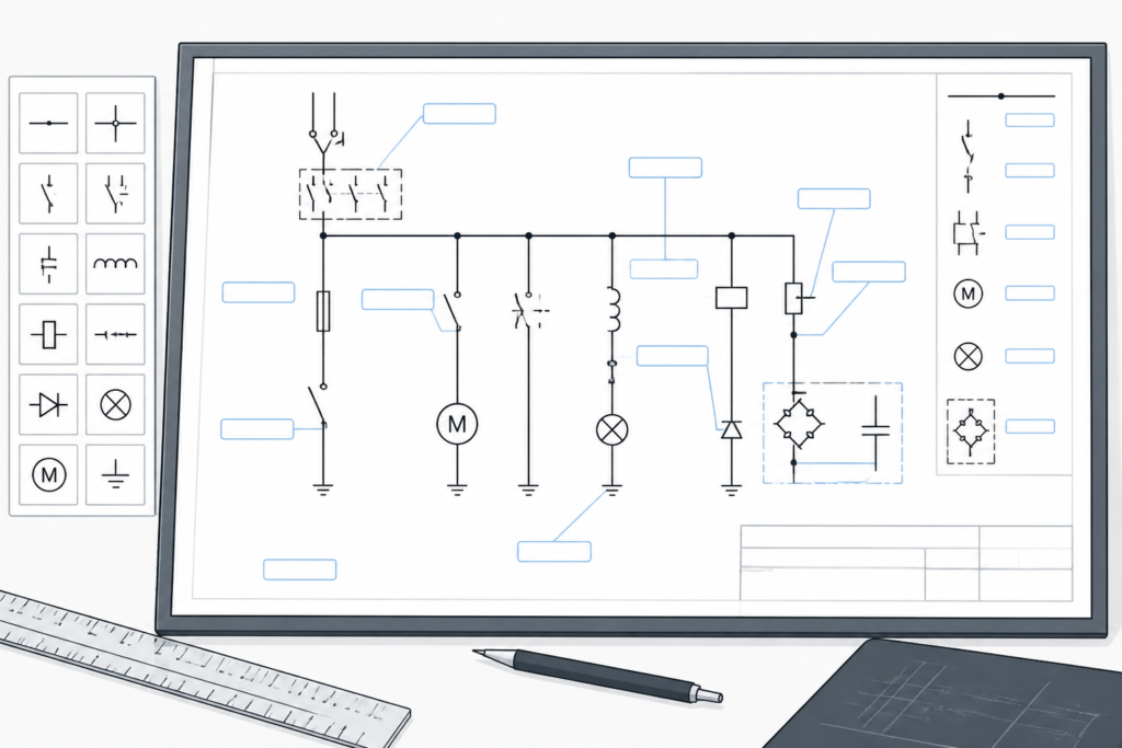
Organize symbols around the drawing system
When adding blocks to an electrical drawing, consider how the symbols will work with layers, linework, text, leaders, and the project title block. Keep symbol insertion behavior predictable and check that block names, attributes, orientation, and visibility settings do not interfere with the office CAD standard.
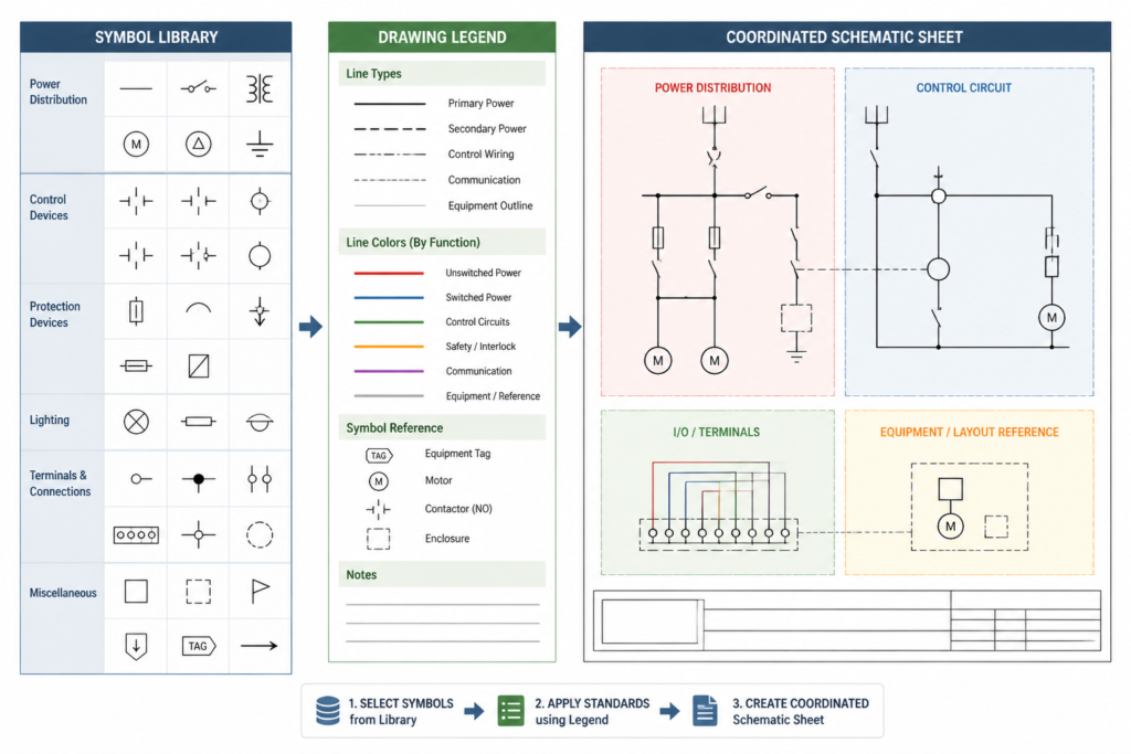
Coordinate symbols with legends and schedules
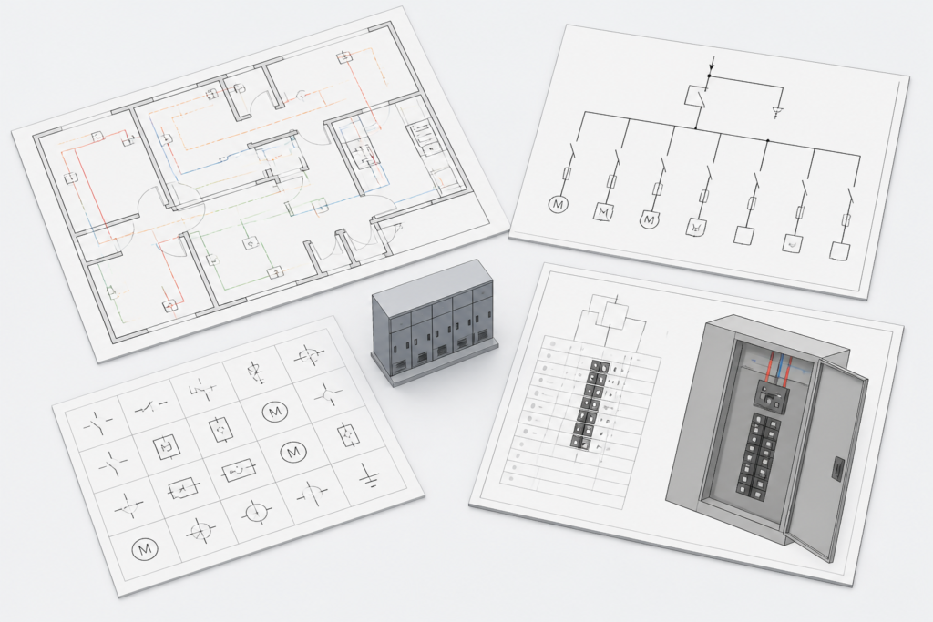
A symbol library is not a replacement for a drawing legend. The legend establishes the meaning used for a particular project, while schedules and equipment documentation provide additional identification and coordination information. Compare the placed symbols with the legend, panel documentation, equipment layouts, and single-line diagram so that related drawings use the same terminology.
Review before issuing the drawing
- Check that connection lines meet the intended symbol insertion points.
- Confirm that symbols remain legible at the plotted drawing scale.
- Look for duplicated, disconnected, mirrored, or unintentionally hidden blocks.
- Verify that annotations and tags agree with the project legend and related documents.
- Keep design verification and electrical safety review with the responsible qualified professionals.
Related electrical CAD reference topics
This resource fits into a broader electrical drafting workflow that may include electrical legends, single-line diagrams, lighting plans, power plans, panel documentation, cable and conduit drafting, and equipment layouts. Reviewing these topics together helps maintain consistent graphic language from the schematic through the coordinated drawing set.
Frequently asked questions
What is included in a schematic wiring symbols DWG?
The source content describes a CAD block collection of schematic wiring symbols intended for electrical design and documentation. Review the downloaded file directly to confirm the available symbols and their specific block content.
Can the DWG be used with AutoCAD?
The source content identifies the file as compatible with AutoCAD and other leading CAD software. Compatibility should still be checked in the version and drafting environment used for the project.
Should these symbols replace an electrical legend?
No. Use the symbols together with the project electrical legend. The legend defines how symbols are interpreted within the drawing set and helps reviewers coordinate related plans and diagrams.
How can I check whether a symbol is correct?
Compare the symbol with the project legend, connection logic, related drawings, equipment information, and applicable design requirements. A qualified electrical professional should resolve uncertain design or safety issues.
Are these symbols suitable for every electrical project?
A general symbol library may support many drafting workflows, but project requirements vary. Confirm the required conventions, attributes, documentation practices, and design criteria before using any symbol in an issued drawing.












Leave a Reply
You must be logged in to post a comment.