
Starters Meters Symbols DWG Blocks provide a practical starting point for electrical schematics, panel layouts, and related CAD documentation. The supplied drawing resource brings starter and meter representations together so drafters can work from a consistent symbol collection instead of recreating common graphics.
Use the source DWG as a drafting reference, then review each symbol against the project legend, office conventions, and applicable design requirements before issuing a drawing. Clear symbol use helps readers distinguish control equipment, measurement devices, and associated connections within an electrical document.
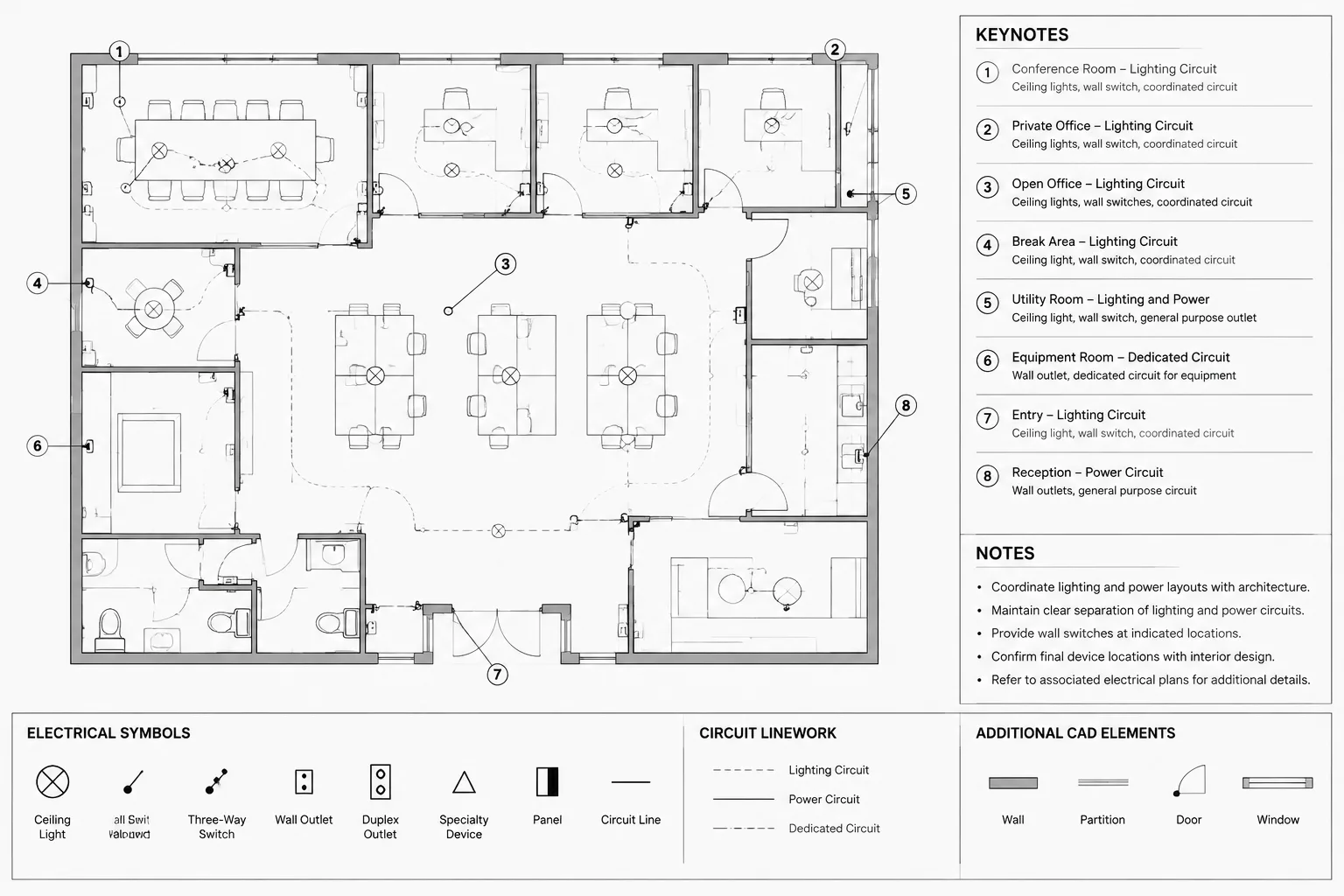
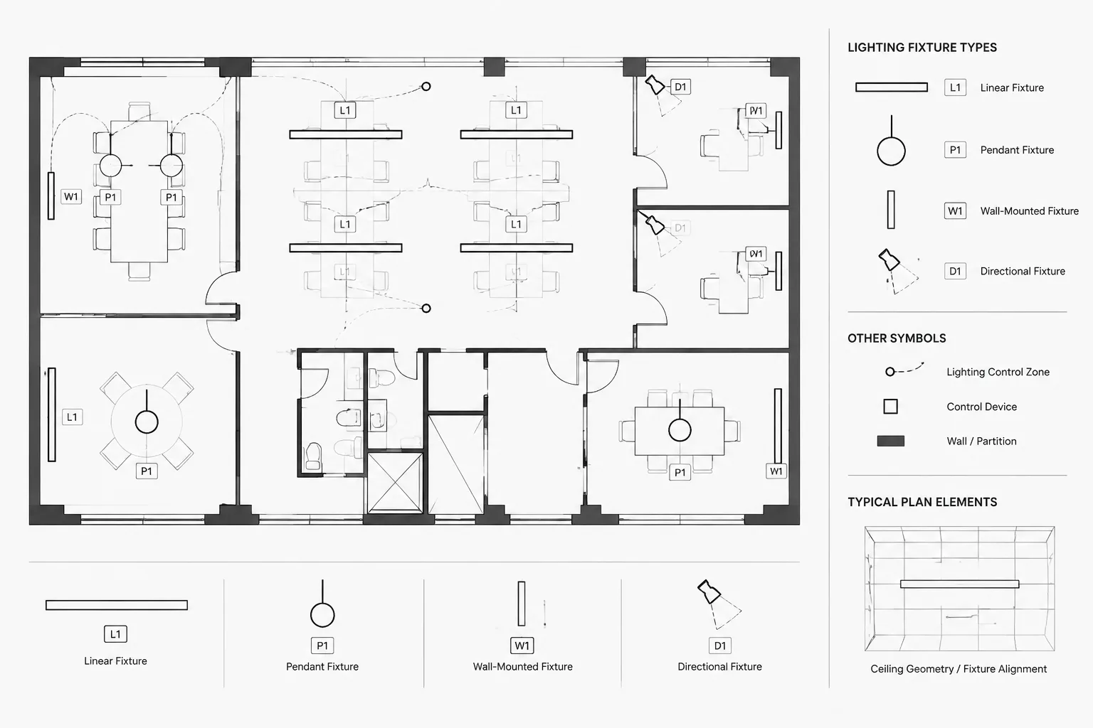
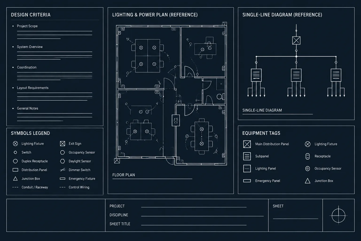
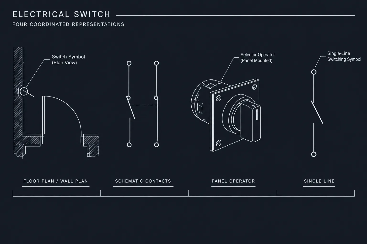
Download our high-quality DWG file featuring **Starters Meters Symbols** for your next electrical or engineering project. This CAD Block provides a comprehensive set of standardized starter and meter symbols, ideal for creating accurate electrical schematics and panel layouts in AutoCAD. With clear and precise representations, these symbols ensure your design documentation meets industry standards. Perfect for electrical engineers, architects, and designers, this DWG file guarantees seamless integration and compatibility with all AutoCAD versions. Enhance your workflow and save time by using these ready-to-use Starters Meters Symbols in your CAD drawings.
Please log in or register to download this file.
How to use starter and meter symbols in electrical drawings
Starter symbols are commonly used to identify equipment associated with starting or controlling motor circuits. Meter symbols identify measurement or monitoring functions. Their meaning depends on the surrounding schematic, panel arrangement, conductor information, and drawing legend, so a block should always be read in context rather than treated as a complete circuit description.
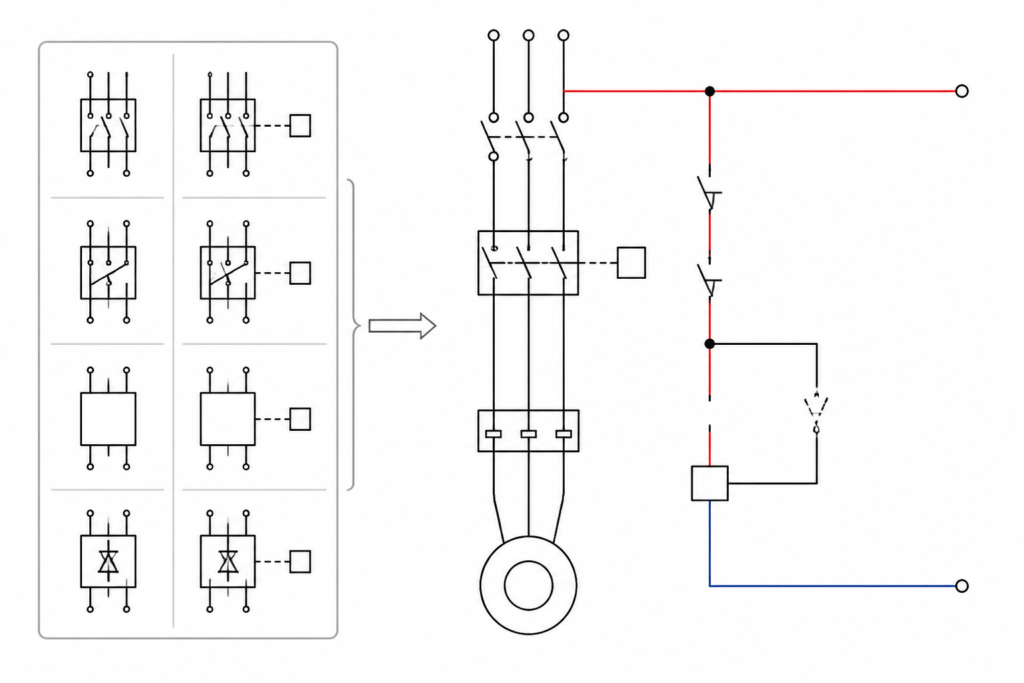
Typical drafting applications
- Schematics: Place symbols where the drawing needs to communicate control, measurement, or equipment relationships.
- Panel layouts: Use the blocks to organize the graphic representation of mounted devices and maintain visual consistency.
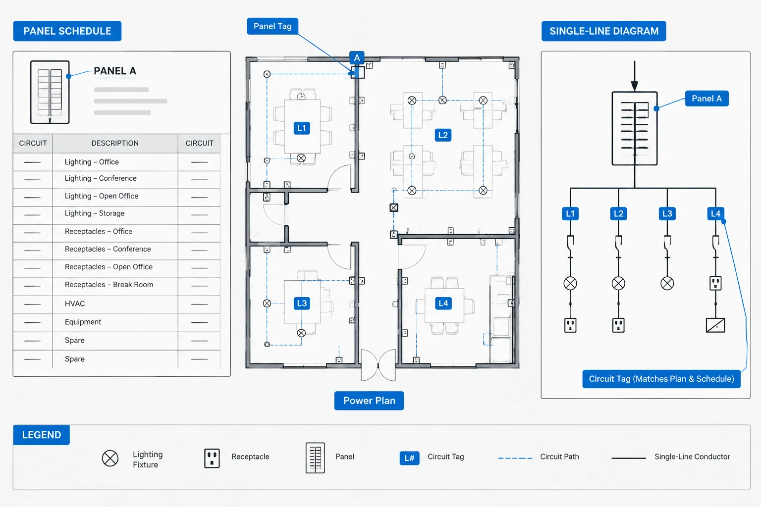
- Single-line documentation: Coordinate the symbol appearance with the project legend and the rest of the distribution drawing.
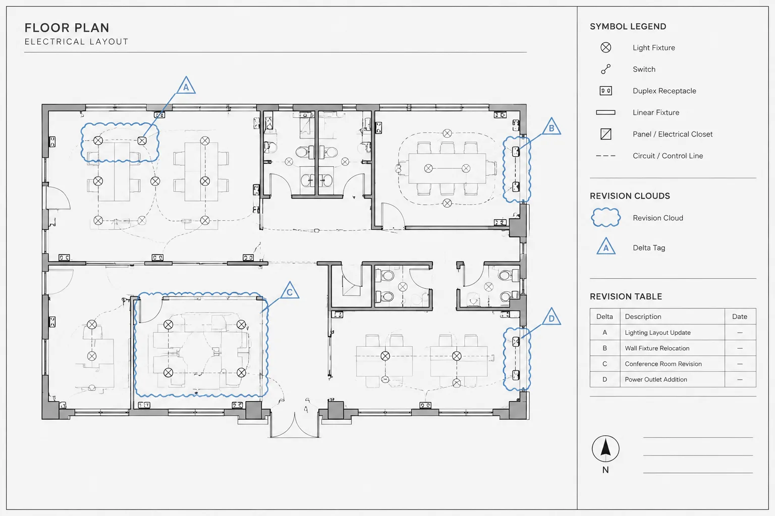
- Equipment layouts: Check orientation, spacing, annotation, and nearby callouts after inserting a block.
Coordination checks before issue
Review the inserted blocks for layer assignment, insertion scale, lineweight, text style, and visibility in the intended plot configuration. Confirm that the symbol is appropriate for the drawing type and that its annotation agrees with the equipment schedule, panel documentation, and electrical legend. A clean block library improves drafting efficiency, but it does not replace engineering review or project-specific documentation requirements.
Why a reusable DWG library helps
A reusable collection reduces repetitive drafting and supports a more uniform visual language across electrical drawings. It can also make coordination easier when multiple sheets use related starter and meter representations. Keep the original source file unchanged, and place project-specific edits in a controlled working copy so the reference block remains available for future drawings.
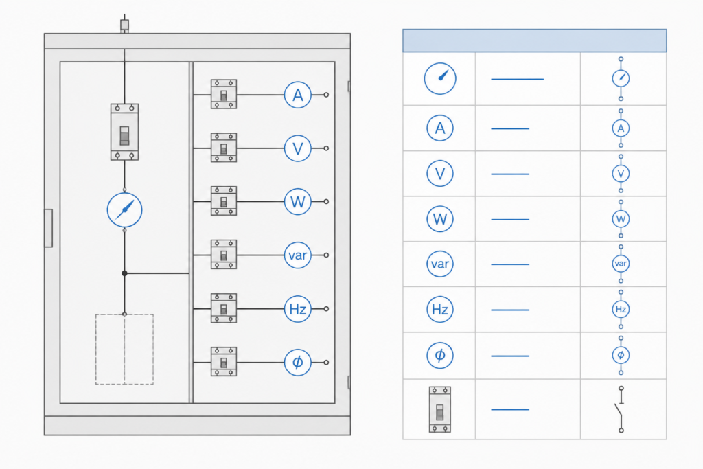
Frequently asked questions
What are Starters Meters Symbols DWG Blocks used for?
They are reusable CAD symbols for representing starter and meter-related devices in electrical schematics, panel layouts, single-line drawings, and related documentation.
Can these symbols be used in any electrical drawing?
They can support many drawing workflows, but each symbol should be checked against the project legend, office drafting practices, and the intended schematic or layout context.
What should be checked after inserting a symbol?
Review its layer, scale, orientation, lineweight, annotation, and plot appearance. Also confirm that the graphic agrees with the associated equipment and drawing references.
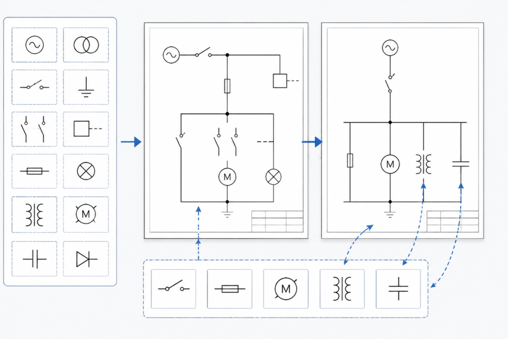
Do the blocks replace engineering review?
No. CAD blocks communicate design information visually; they do not determine equipment selection, circuit performance, protection, installation requirements, or compliance. Those items require qualified project review.
How should the DWG resource be managed?
Keep a clean reference copy and use a controlled working copy for project adjustments. This helps preserve the original symbol set while allowing coordination with project-specific layers and annotation standards.


Leave a Reply
You must be logged in to post a comment.