
Meter symbols help communicate the location and type of metering equipment without drawing every physical component in detail. This DWG resource provides reusable CAD blocks for representing meters in electrical, water, gas, and utility documentation.
Use the blocks as part of a coordinated drafting workflow alongside electrical legends, schematic symbols, single-line diagrams, equipment layouts, and other MEP drawing references. Before issuing a drawing, confirm that each symbol matches the project legend and the documentation requirements established by the responsible design team.
Discover a comprehensive collection of **Meter Symbols DWG files and CAD Blocks** designed for seamless integration into your AutoCAD projects. This downloadable DWG file includes high-quality, professionally drafted meter symbols suitable for electrical, water, gas, and utility schematic drawings. These meter symbols help architects, engineers, and designers quickly and accurately represent meters in construction and MEP plans. The CAD Block is fully compatible with AutoCAD and other leading CAD software, ensuring easy insertion and editing. Enhance your technical drawings with standardized meter symbols, improve project documentation, and streamline your workflow with this essential resource.
Please log in or register to download this file.
How to use meter symbols in CAD drawings
Meter blocks are graphical references, not installation instructions or evidence of a device’s rating, connection method, or approval status. Their purpose is to make the presence and general category of metering equipment easy to recognize in plans, diagrams, and utility documentation.
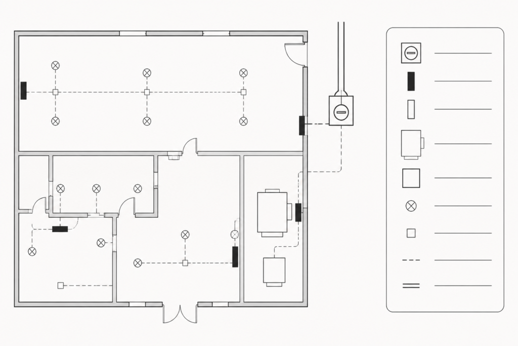
Choose the symbol by drawing purpose
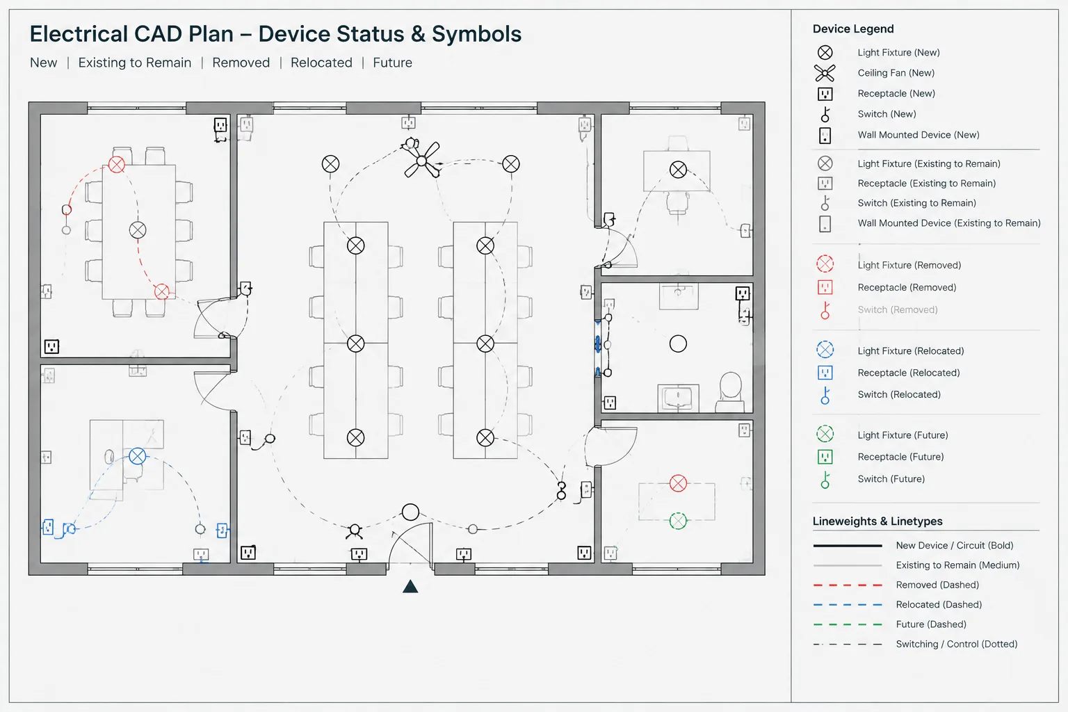
The appropriate representation depends on the discipline and drawing type. An electrical plan may use a meter symbol to identify metering equipment within a power distribution layout, while a utility or building-services drawing may use a related symbol for water or gas metering. Keep the symbol’s meaning consistent with the project legend.
Coordinate symbols with the drawing set
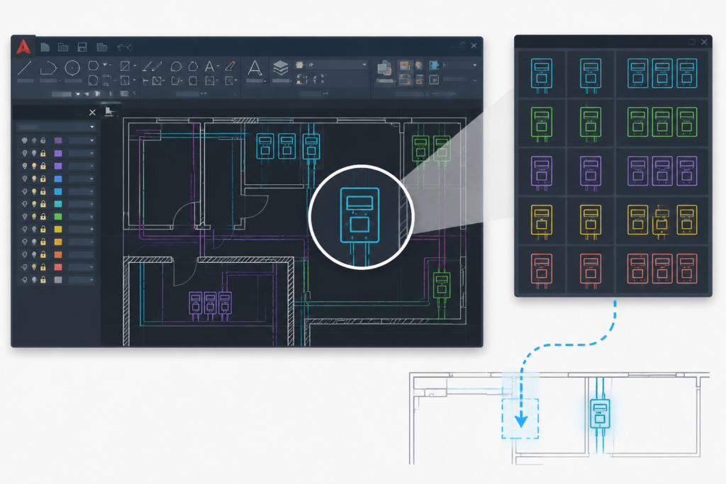
When inserting a block, check its visibility, orientation, layer behavior, annotation, and relationship to nearby equipment. Coordination with panel schedules, distribution diagrams, equipment layouts, and cable or conduit drafting helps prevent a symbol from being mistaken for a physical clearance, route, or connection detail.
Why reusable DWG blocks are useful
Reusable blocks support consistent documentation and reduce repetitive drafting. Because the file is intended for AutoCAD and compatible CAD workflows, users can insert and edit the symbols as needed while preserving the project team’s drafting conventions. Any editing should remain visually clear and should not change the technical meaning assigned by the project documentation.
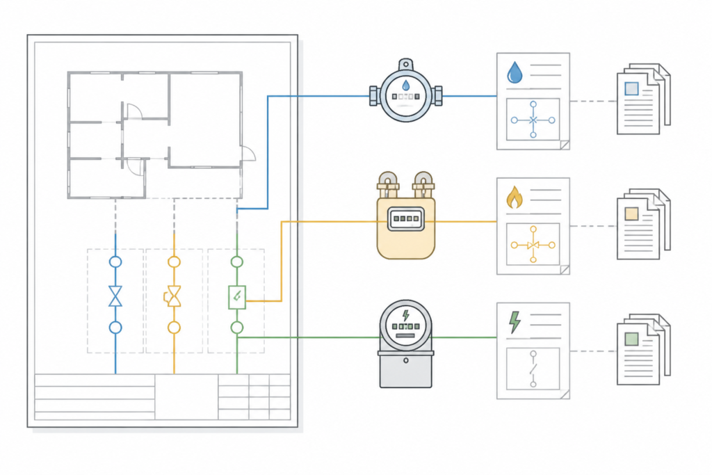
Related CAD reference topics
- Electrical legends and schematic symbol organization
- Single-line diagram drafting concepts
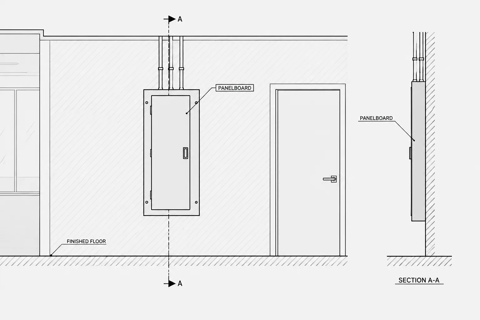
- Panel and distribution documentation
- Equipment layout and utility coordination
- Cable and conduit representation in plans
Use the downloadable resource below as a drafting aid. Engineering design decisions, device selection, installation details, and field work require review by qualified professionals; do not use a drawing symbol as a substitute for approved design documentation or safe work procedures.
Frequently asked questions
What are Meter Symbols DWG Blocks used for?
They are reusable CAD representations of meters for electrical, water, gas, and utility schematic or MEP drawings.
Can these meter symbols be edited in AutoCAD?
Yes. The source content identifies the file as compatible with AutoCAD and other leading CAD software, allowing users to insert and edit the blocks within their drafting workflow.
Should a meter symbol be treated as an installation detail?
No. A symbol communicates the presence or general category of equipment. It does not by itself define ratings, connections, clearances, installation requirements, or approval status.
How should I keep meter symbols consistent across a project?
Follow the project legend, layer standards, annotation conventions, and drawing coordination requirements. Use the same graphical meaning wherever the symbol appears.
Can these blocks be used in utility and MEP drawings?
They are intended for use in electrical, water, gas, and utility schematic documentation and can support coordinated MEP drafting when reviewed against the project requirements.










Leave a Reply
You must be logged in to post a comment.