
An Electrical General Symbols DWG can provide a practical starting point for organizing common elements in electrical drawings. Instead of redrawing familiar graphical items, CAD users can review the supplied block collection, select the symbols needed for a project, and incorporate them into an established drafting workflow.
This resource is intended for engineers, architects, designers, and CAD technicians who prepare electrical plans, schematics, legends, and coordination drawings. Always review each symbol against the project’s drawing conventions and the requirements of the responsible design professional before issuing documentation.
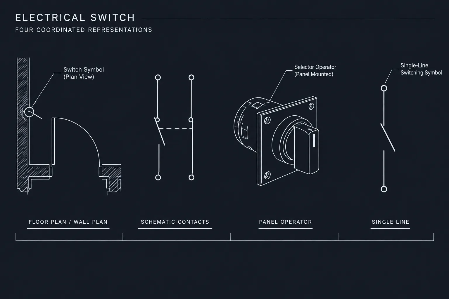
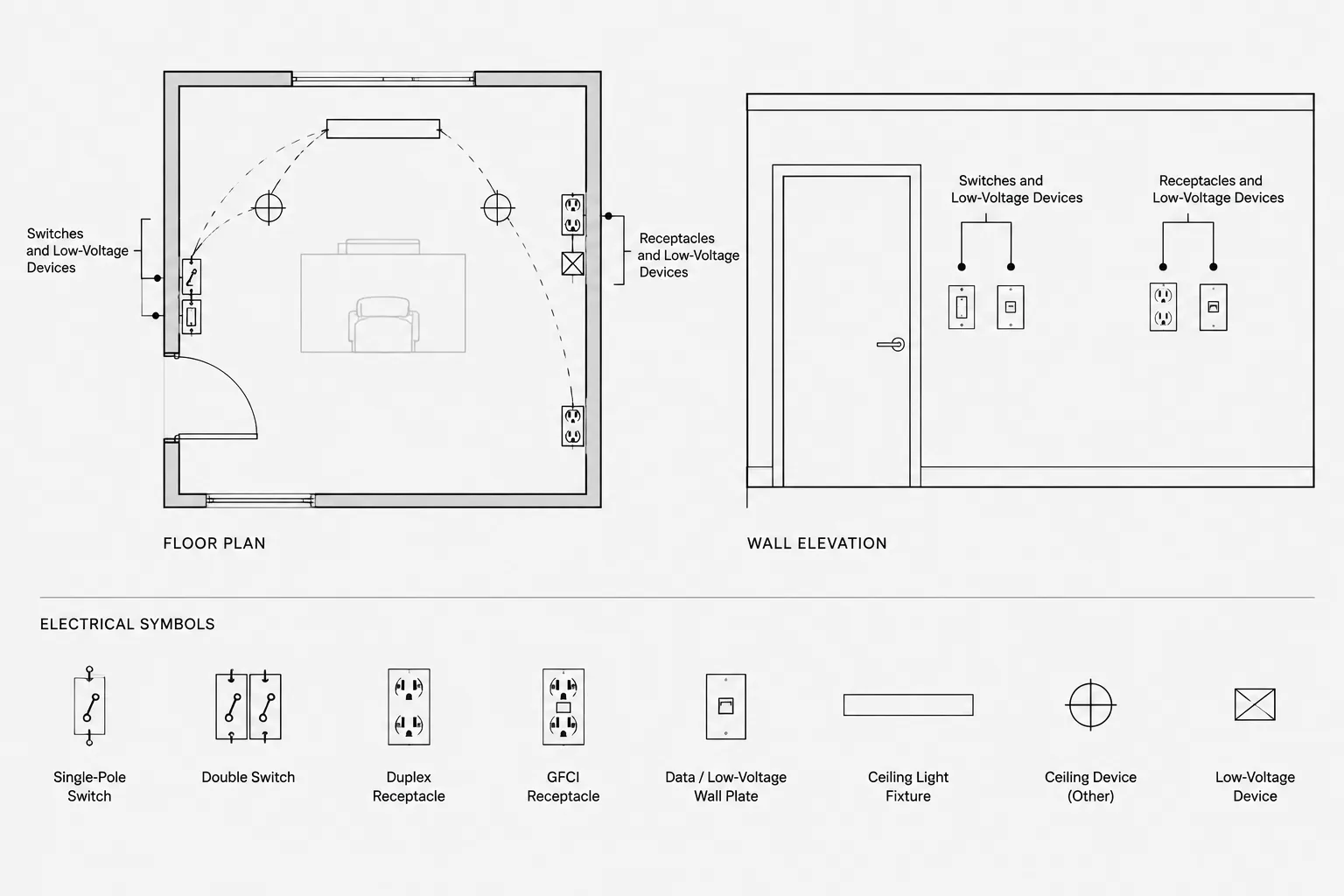
Discover a comprehensive collection of Electrical General Symbols in a high-quality DWG file, perfect for your next electrical design project. This CAD block includes a wide range of standard electrical symbols, such as switches, outlets, lighting fixtures, and more, streamlining the drafting process for engineers, architects, and designers. Easily compatible with AutoCAD and other popular CAD software, these symbols ensure precise and professional schematics for residential, commercial, and industrial applications. Save time and enhance accuracy by integrating this versatile Electrical General Symbols DWG file into your design workflow today.
Please log in or register to download this file.
How to use an Electrical General Symbols DWG
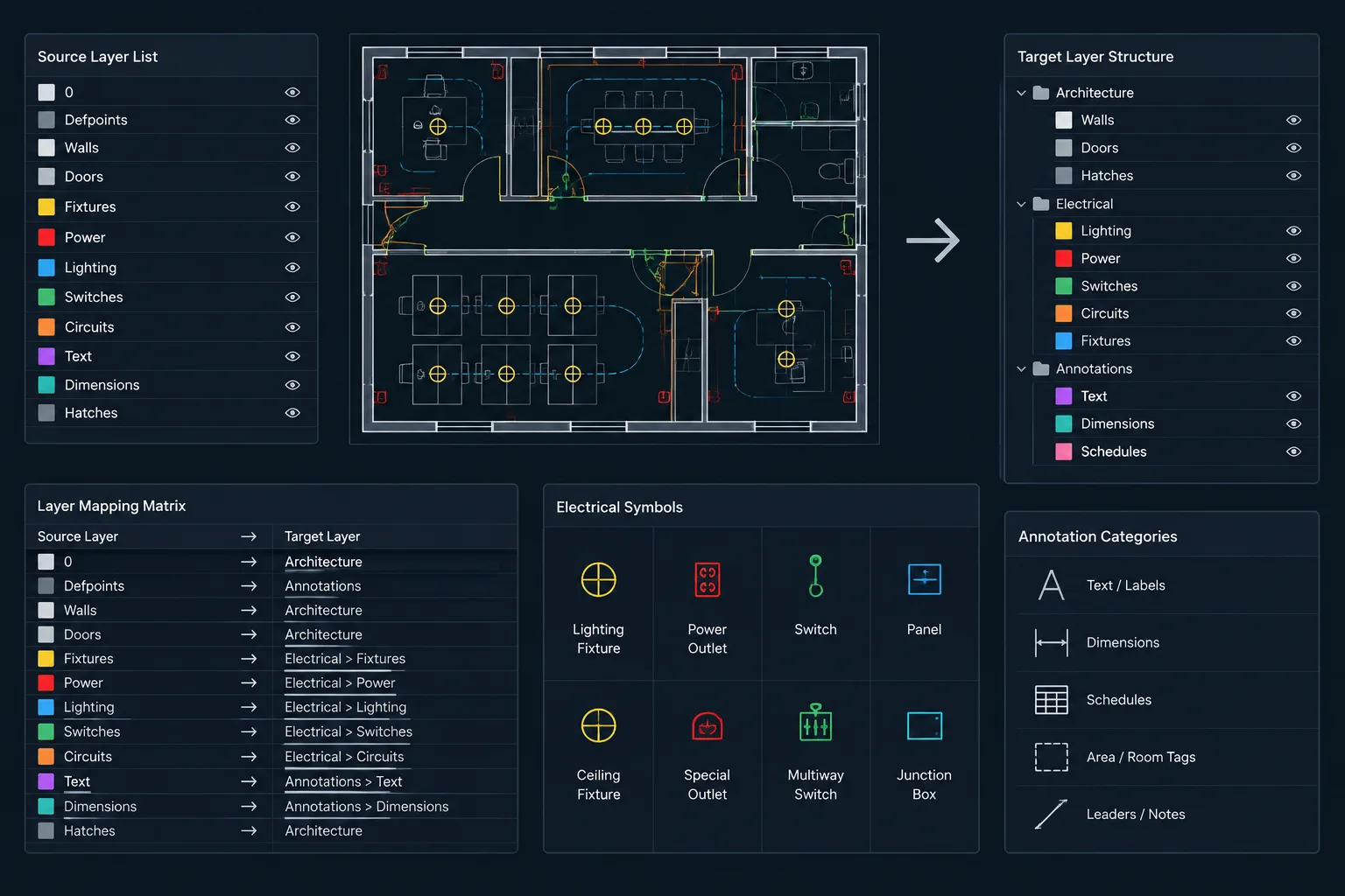
After opening the file in AutoCAD or compatible CAD software, inspect the block organization, insertion behavior, layer assignments, text appearance, and orientation of the symbols. A quick review helps identify how the content will behave when copied into a project drawing and whether it matches the office template.

Coordinate symbols with the drawing legend
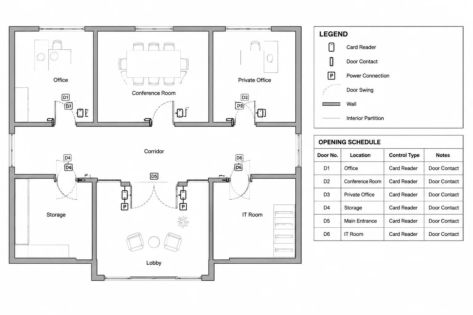
Electrical symbols only communicate reliably when they are used consistently. Compare the supplied graphics with the project legend, sheet notes, and related electrical documentation. If a project uses customized annotations or graphical conventions, maintain a clear distinction between the original block content and any office-specific revisions.
Support plan and schematic drafting
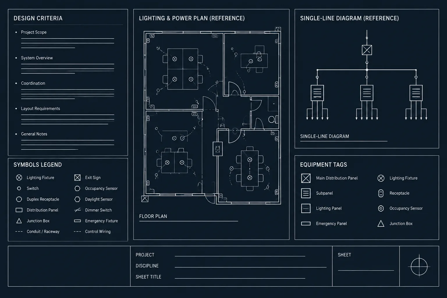
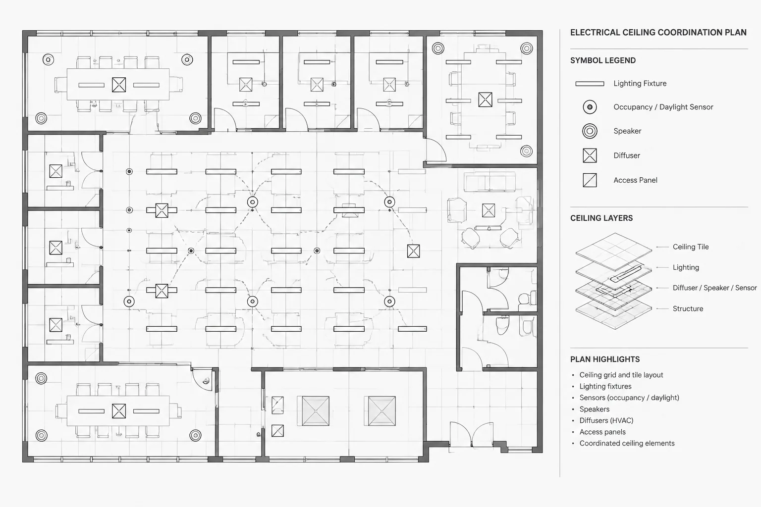
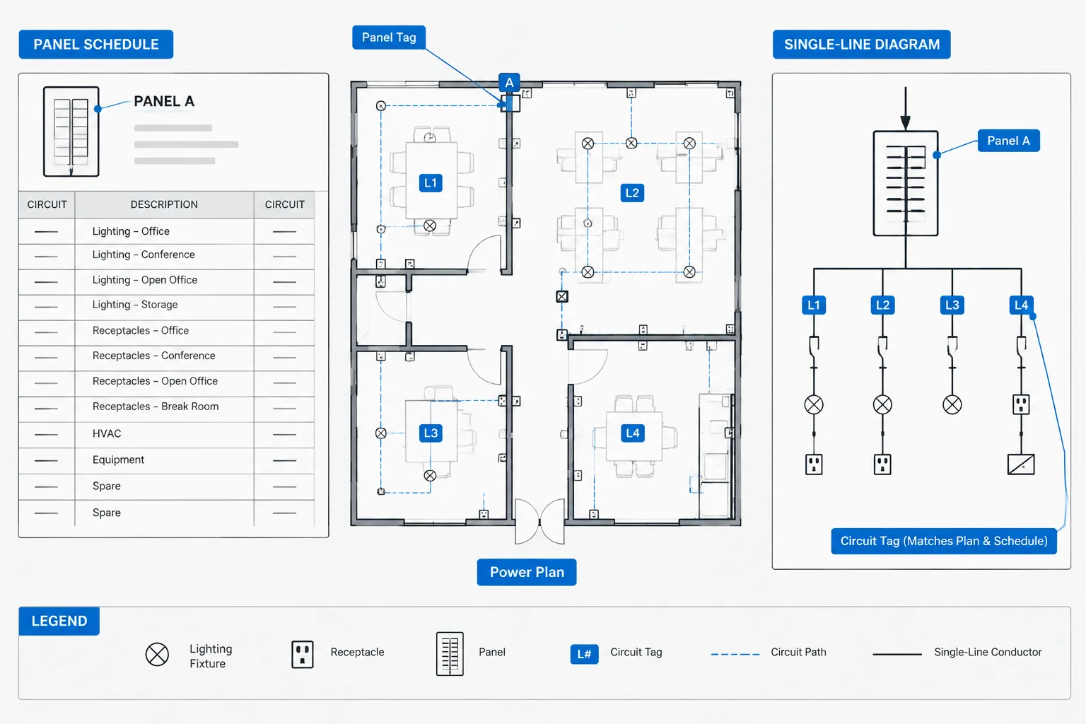
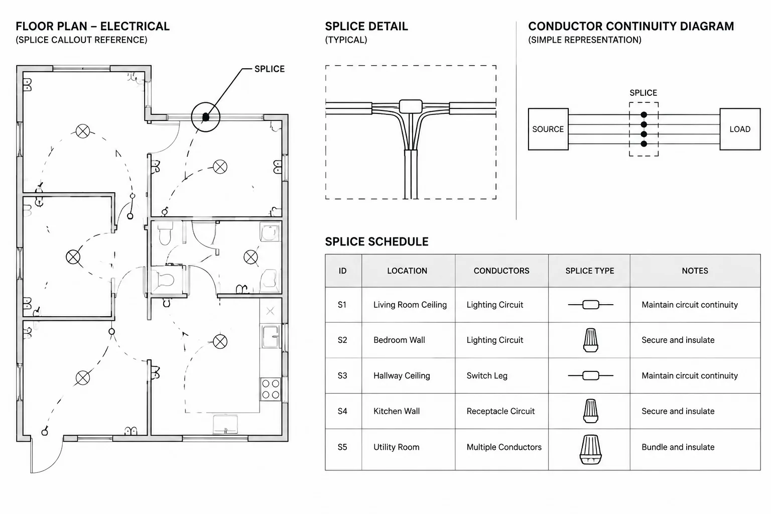
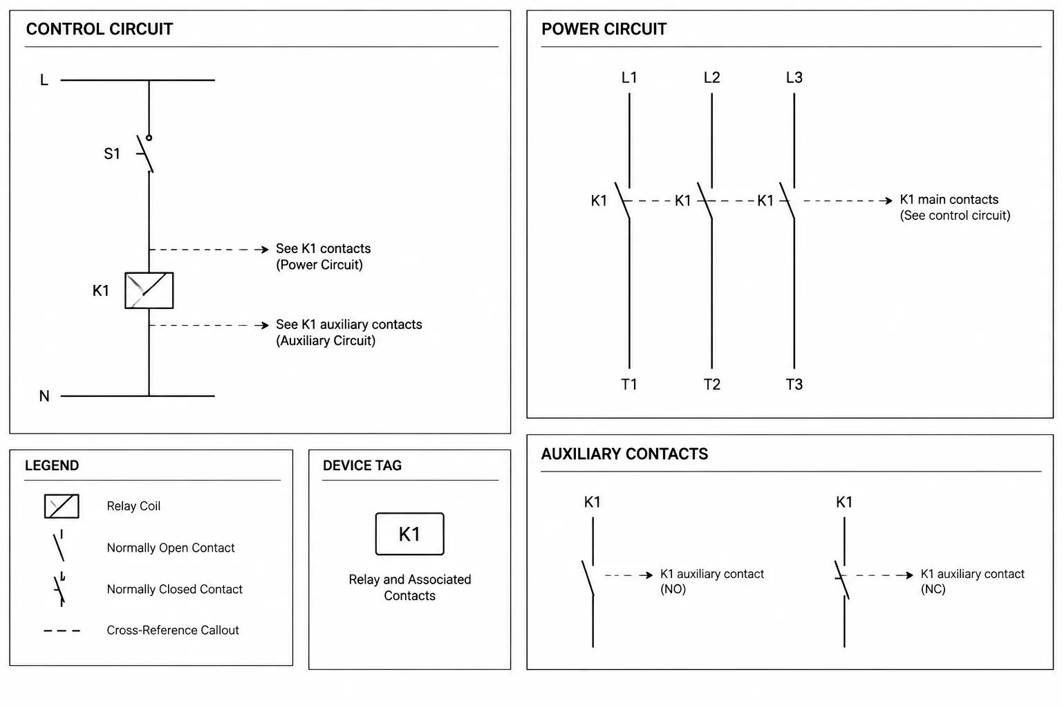
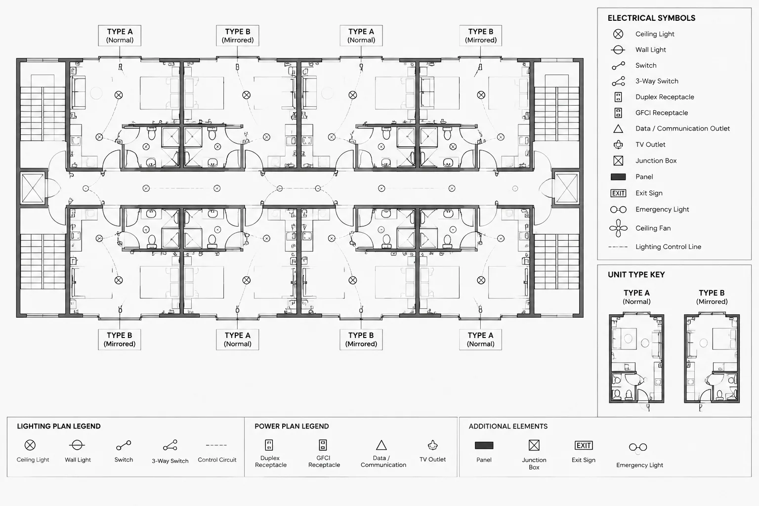
The collection can help organize drafting for lighting layouts, power plans, equipment documentation, and schematic or single-line diagram work. Symbol selection should follow the purpose of the drawing: a plan view may need location-based graphics, while a schematic emphasizes functional relationships and connection logic.
Useful related reference topics
- Electrical legend organization and annotation practices
- Lighting and power plan drafting concepts
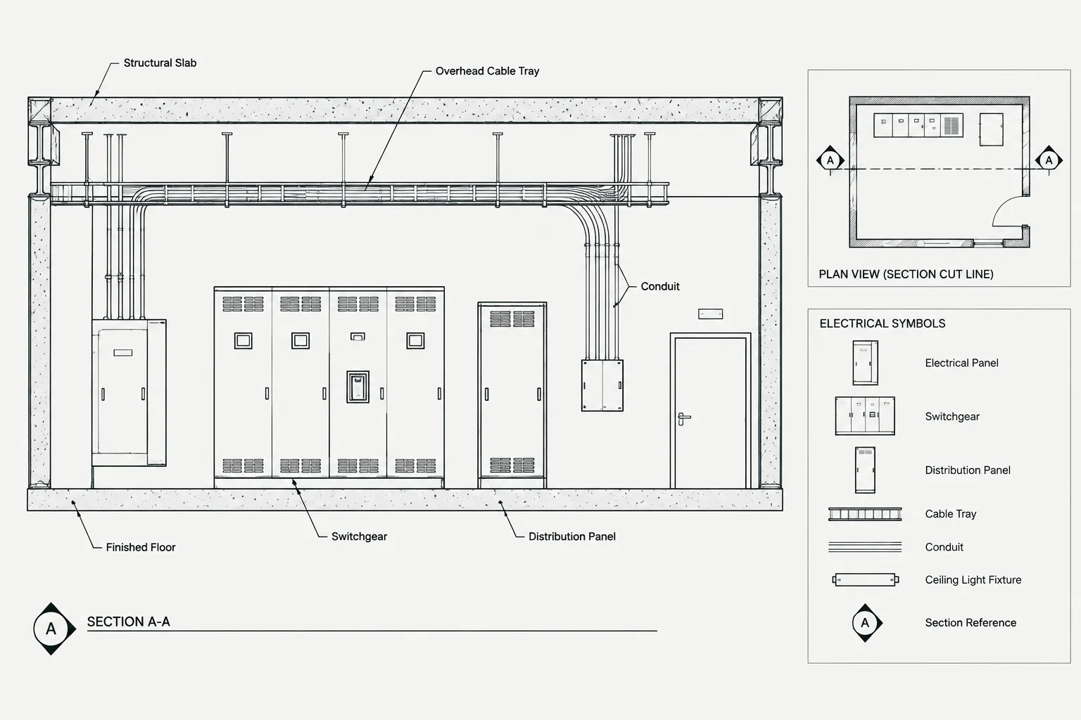
- Panel and distribution documentation
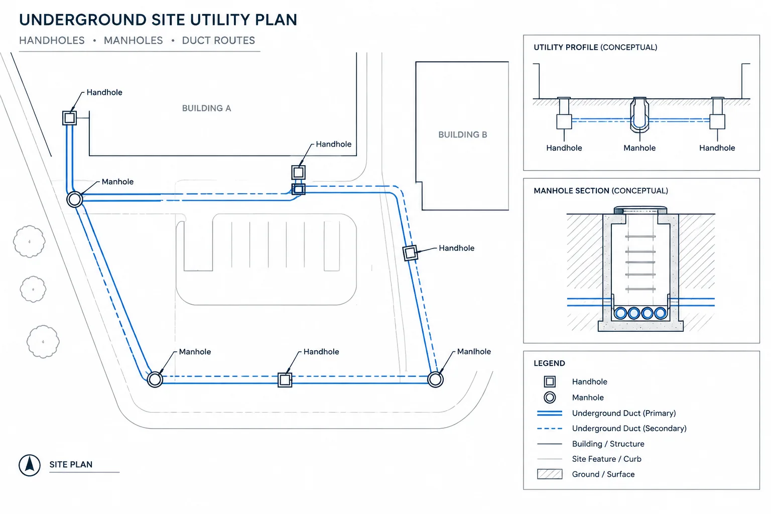
- Cable and conduit drafting concepts
- Single-line diagram symbols and layout conventions
- Equipment layout coordination in CAD
This DWG is a drafting reference, not a substitute for design verification. Confirm symbol meaning, equipment identification, connections, and applicable project requirements before the drawing is used for construction, permitting, fabrication, or field work.

Frequently asked questions
What is included in this Electrical General Symbols DWG?
The source description identifies a collection of general electrical symbols, including switches, outlets, lighting fixtures, and other commonly used drafting elements.
Can the DWG be opened in AutoCAD?
The file is presented as compatible with AutoCAD and other popular CAD software. Confirm compatibility in the software version and project environment used by your team.

Can these symbols be used in residential, commercial, and industrial drawings?
The source description presents the collection for residential, commercial, and industrial applications. Review every symbol against the conventions and documentation requirements of the specific project.
Should the symbols be edited before use?
They may need to be reviewed or adjusted to match project layers, annotation styles, block behavior, and the electrical legend. Preserve a controlled original copy when making office-specific changes.
Does using the DWG replace electrical design review?
No. A symbol library supports drafting efficiency, but qualified project personnel must verify the design, interpretation, coordination, and applicable requirements before issue.
Leave a Reply
You must be logged in to post a comment.