
MOSFET symbols DWG files help engineers, designers, and CAD drafters represent MOSFET devices consistently in electronic schematics and electrical documentation. A reusable symbol library can reduce repetitive drafting work while supporting clearer, more uniform drawings.
This resource is intended for AutoCAD users and related CAD workflows. Review the included symbols before placing them in a project so that the selected representation matches the device type, drawing convention, and documentation requirements.
Download a high-quality DWG file featuring detailed MOSFETs symbols, perfect for engineers and designers working on electronic circuit schematics. This CAD Block includes various standard MOSFETs symbols, ensuring accuracy and consistency in your AutoCAD projects. Use this file to streamline the design of PCB layouts, electrical diagrams, and technical documentation. The DWG format guarantees seamless compatibility with AutoCAD and other leading CAD software, making it an essential resource for professionals needing precise MOSFETs symbols for their electrical engineering applications and design workflows.
Please log in or register to download this file.
Using MOSFET symbols in CAD drawings
MOSFET symbols are graphical references used to identify field-effect transistor devices within circuit schematics. In a drawing, the symbol communicates the device’s intended connection points and helps readers understand how the component relates to nearby circuitry.
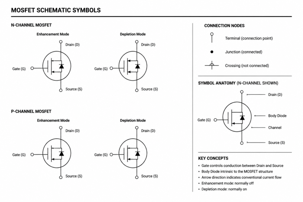
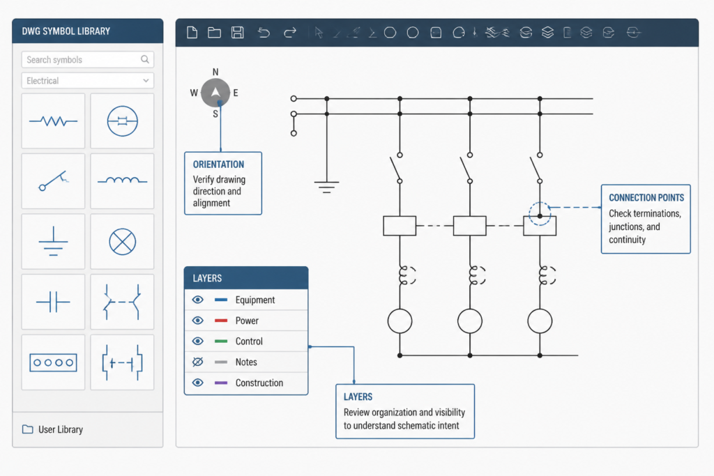
When adding a MOSFET symbol to a schematic, check its orientation, labeling, and connection points against the project’s electrical legend or drafting standard. Consistent placement and readable annotation are especially important when the schematic is later coordinated with PCB documentation, equipment layouts, panel drawings, or other electrical design records.
What to check before using the DWG block
- Confirm that the symbol matches the device representation required by the project.
- Review layer assignments, linework, text, and insertion behavior in the target CAD environment.
- Check that connection points align correctly with wires and related schematic elements.
- Use the project’s established naming, orientation, and annotation conventions.
- Coordinate the symbol with the electrical legend and associated documentation before issuing a drawing.
Related CAD documentation topics
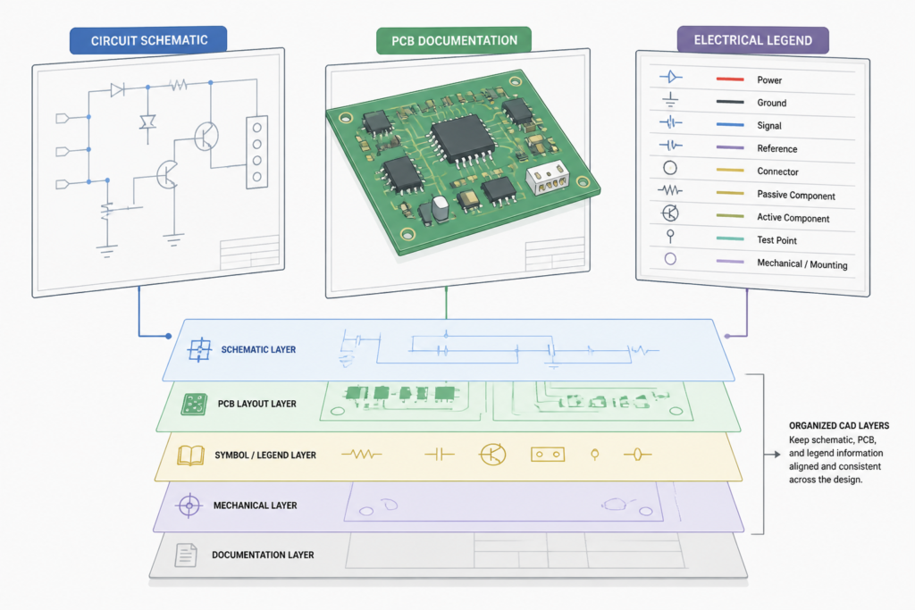
MOSFET symbols are most useful when coordinated with broader electrical CAD practices, including schematic symbols, single-line diagram concepts, electrical legends, PCB documentation, and equipment layout drafting. Keeping these references consistent helps reduce ambiguity between design views without replacing the project engineer’s review or the governing documentation requirements.
Download and review workflow
Download the DWG block, open it in a compatible CAD application, and inspect the geometry before incorporating it into a working drawing. Save any project-specific edits in accordance with your office CAD standards, and do not use a generic symbol as a substitute for verifying the actual component documentation.
Frequently asked questions
What is included in the MOSFET symbols DWG?
The source file contains detailed MOSFET CAD symbols intended for use in electronic circuit schematics, electrical diagrams, and technical documentation.
Can the DWG file be used with AutoCAD?
Yes. The file is provided in DWG format for AutoCAD workflows and may also be usable in other CAD applications that support the format. Confirm compatibility in your installed software before production use.
Are these symbols ready for every electrical project?
They are drafting resources, not project-specific engineering approvals. Review the symbol style, connection points, labels, and device representation against the applicable project requirements before issuing a drawing.
Can the symbols be used in PCB documentation?
The source content identifies PCB layouts, electrical diagrams, and technical documentation as intended use areas. Coordinate the symbol with the project’s schematic and component documentation before using it in a PCB-related workflow.
Should I edit the downloaded CAD block?
Edits may be appropriate when required by an office or project drafting standard. Preserve clear connection points and verify that any changes do not alter the intended device representation.












Leave a Reply
You must be logged in to post a comment.