
Resistor symbols DWG files help drafters represent resistance-related components consistently in electrical and electronic schematics. A reusable CAD block collection can save drafting time while keeping circuit diagrams easier to read, revise, and coordinate.
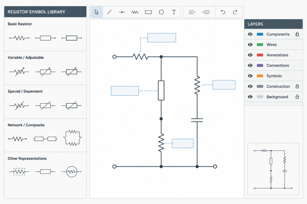
The supplied DWG resource contains a collection of resistor symbols for use with AutoCAD and other compatible CAD software. Use it as a drafting reference when preparing schematic sheets, educational diagrams, equipment documentation, and electrical drawing legends.
Discover a comprehensive DWG file featuring a collection of Resistors Symbols, perfect for electrical and electronic schematic designs. This high-quality CAD Block includes various standard resistor symbols used in circuit diagrams, making it ideal for engineers, architects, and designers. Easily integrate these Resistors Symbols into your projects to enhance clarity and professionalism. Compatible with AutoCAD and other leading CAD software, this DWG file streamlines your workflow and ensures accuracy in technical drawings. Suitable for educational, industrial, and professional use cases, download now to improve your CAD designs with essential resistor representations.
Please log in or register to download this file.
What resistor symbols communicate
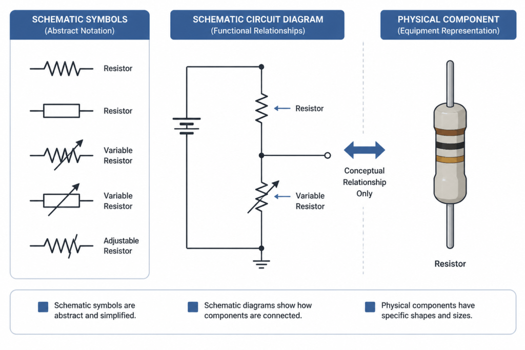
A resistor symbol identifies a passive circuit component in a schematic and shows where that component fits within the circuit representation. The symbol is an abstract drawing convention rather than a picture of the physical device. Its purpose is to support circuit tracing, component identification, and communication between designers, reviewers, and installers.
Using resistor CAD blocks in electrical drawings
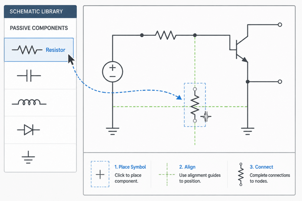
Insert the selected symbol into the schematic at the appropriate connection point, then coordinate its orientation and nearby annotation with the drawing layout. Keep symbols aligned with the drawing’s visual language so that circuit paths remain easy to follow. The block should be reviewed for scale, insertion behavior, linework, and compatibility with the target CAD environment before it is incorporated into a project file.
Drafting and layer considerations
Electrical CAD projects commonly separate schematic graphics, annotation, references, and construction or documentation notes by layer. Follow the project’s established layer naming, color, linetype, and plotting conventions rather than assuming that a downloaded block matches every office standard. Where a resistor symbol collection includes alternatives, select the representation that matches the project legend and the surrounding schematic style.
Symbol library context
Resistor blocks are most useful when treated as part of a broader electrical symbol library. They may be coordinated with connection symbols, switches, sources, terminals, signal references, and equipment identifiers. A consistent library improves drawing readability, but it does not replace project-specific design review or verification of the final schematic.
Practical review checklist
- Confirm that the selected symbol matches the intended schematic convention.
- Check orientation, insertion point, lineweight, and annotation clearance.
- Verify that the block behaves correctly in the destination CAD software.
- Keep the symbol coordinated with the project legend and layer standards.
- Review the completed circuit representation for legibility and connection continuity.
Frequently asked questions
What is included in a resistor symbols DWG file?
The supplied resource is described as a collection of resistor symbols for electrical and electronic schematic designs. The exact available representations should be reviewed in the DWG file before use.
Can the resistor symbols be used in AutoCAD?
Yes. The source describes the file as compatible with AutoCAD and other leading CAD software. Always test imported blocks in the target drawing environment and confirm that their layers and annotations follow the project setup.
Are resistor symbols used for schematics or physical layouts?
Resistor symbols primarily represent circuit components in schematic diagrams. They should not be interpreted as a detailed physical installation layout, equipment model, or verified design solution.
How should a resistor symbol be placed on a drawing?
Place it along the relevant schematic connection path, orient it consistently with adjacent symbols, and provide enough room for references or notes. The final arrangement should follow the project legend and drafting conventions.
Can this DWG replace an electrical symbol standard or project legend?
No. A CAD block is a drafting resource. The project team should confirm the selected representation against the applicable drawing conventions, office library, and design documentation requirements.












Leave a Reply
You must be logged in to post a comment.