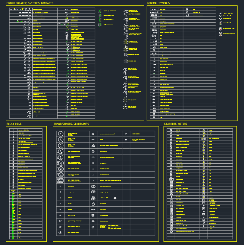
AutoCAD electrical symbols provide a consistent visual language for schematics, panel drawings, control diagrams, and related electrical documentation. This DWG collection brings together commonly used symbol categories, including circuit breakers, switches, contacts, relay coils, transformers, generators, starters, and meters.
Use the symbols as drafting resources rather than assuming that every project follows the same graphic convention. Before placing a block, compare its appearance and meaning with the project legend, drawing standard, and documentation requirements. The original file information and download control are preserved below.
This comprehensive DWG file features a wide range of essential electrical symbols, including circuit breakers, switches, contacts, relay coils, transformers, generators, starters, and meters. Perfect for architects, engineers, and electrical designers, this CAD block collection streamlines the creation of professional electrical schematics and panel layouts. Each symbol is meticulously designed for clarity and accuracy, ensuring compliance with standard electrical drafting practices. The DWG file is fully compatible with AutoCAD and other leading CAD software, enabling seamless integration into your projects. Ideal for use in residential, commercial, and industrial electrical design applications. Download now to enhance your electrical drawings with high-quality, ready-to-use symbols.
Please log in or register to download this file.
What Is Included in This Electrical Symbol Collection?
The file groups several types of electrical symbols that commonly appear in schematic and equipment documentation. Each category serves a different communication purpose, so the symbol name, tag, and surrounding connections should make its intended function clear.
Circuit Breakers and Switches
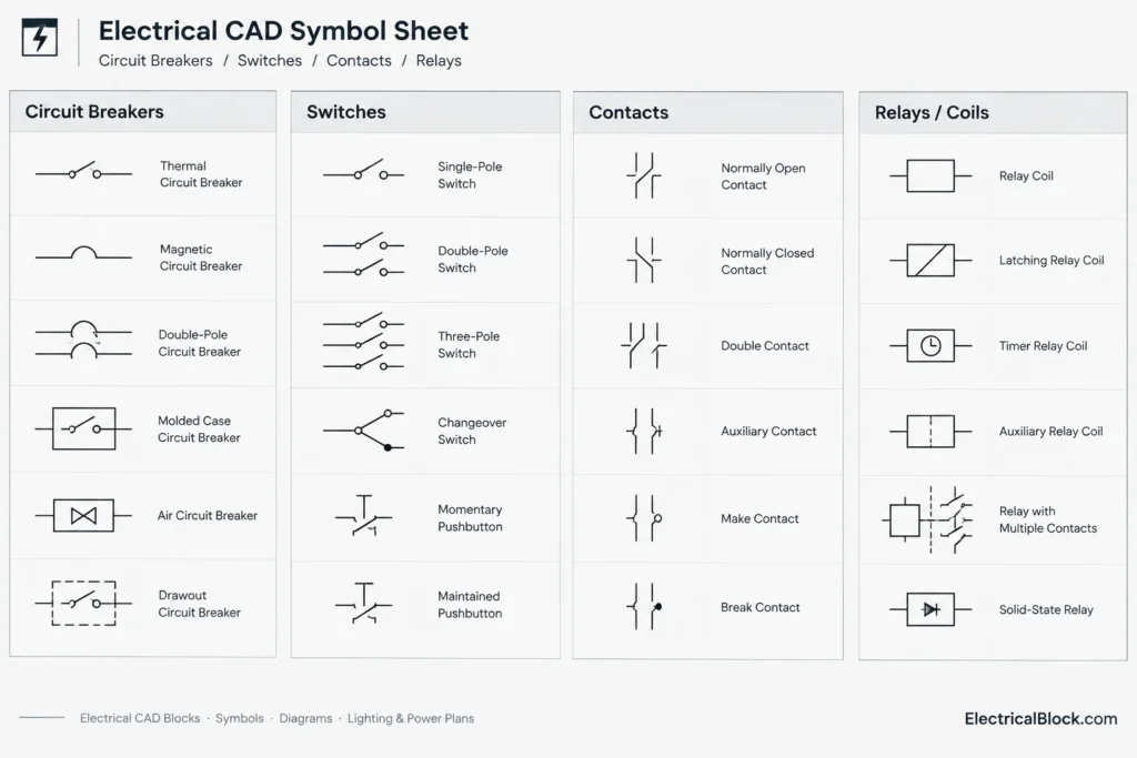
Circuit breaker symbols identify protective switching devices in diagrams. Switch symbols represent intentional changes in circuit state or routing. Their exact graphics can vary between drawing conventions, making a clear legend especially important when symbols are reused across projects.
Contacts and Relay Coils
Contacts and relay coils are often shown as related elements within control diagrams. Good documentation uses consistent device tags so readers can associate a coil with the contacts it operates. Contact state descriptions should also match the project convention rather than relying only on visual interpretation.
Transformers and Generators
Transformer and generator symbols are typically used to identify power sources or conversion equipment within a schematic or single-line-diagram context. Equipment labels, connection lines, and drawing notes provide the project-specific information that a generic symbol cannot communicate by itself.
Starters and Meters
Starter symbols help identify motor-control functions, while meter symbols indicate measurement or monitoring points. When these blocks are placed in a drawing, nearby tags and annotations should distinguish the actual device or measured quantity.
Practical DWG Review Checklist
- Inspect the geometry: Confirm that lines, arcs, fills, and connection points display correctly.
- Review layers: Move or map symbol objects to the project layer structure where necessary.
- Check insertion scale: Compare each block with the surrounding diagram and drawing units.
- Confirm orientation: Rotate or mirror symbols only when doing so preserves their intended meaning.
- Standardize labels: Apply the project’s device tags, text styles, and annotation format.
- Remove duplicates: Check block names before importing the collection into an established CAD library.
- Update the legend: Ensure every symbol used in the drawing is defined clearly for reviewers and installers.
Using the Symbols in Electrical Documentation
A symbol library is most useful when it supports a controlled CAD workflow. Consider keeping approved blocks on dedicated electrical layers and using predictable names for symbol definitions. This makes it easier to search the drawing, revise repeated devices, and maintain consistent plotting behavior.
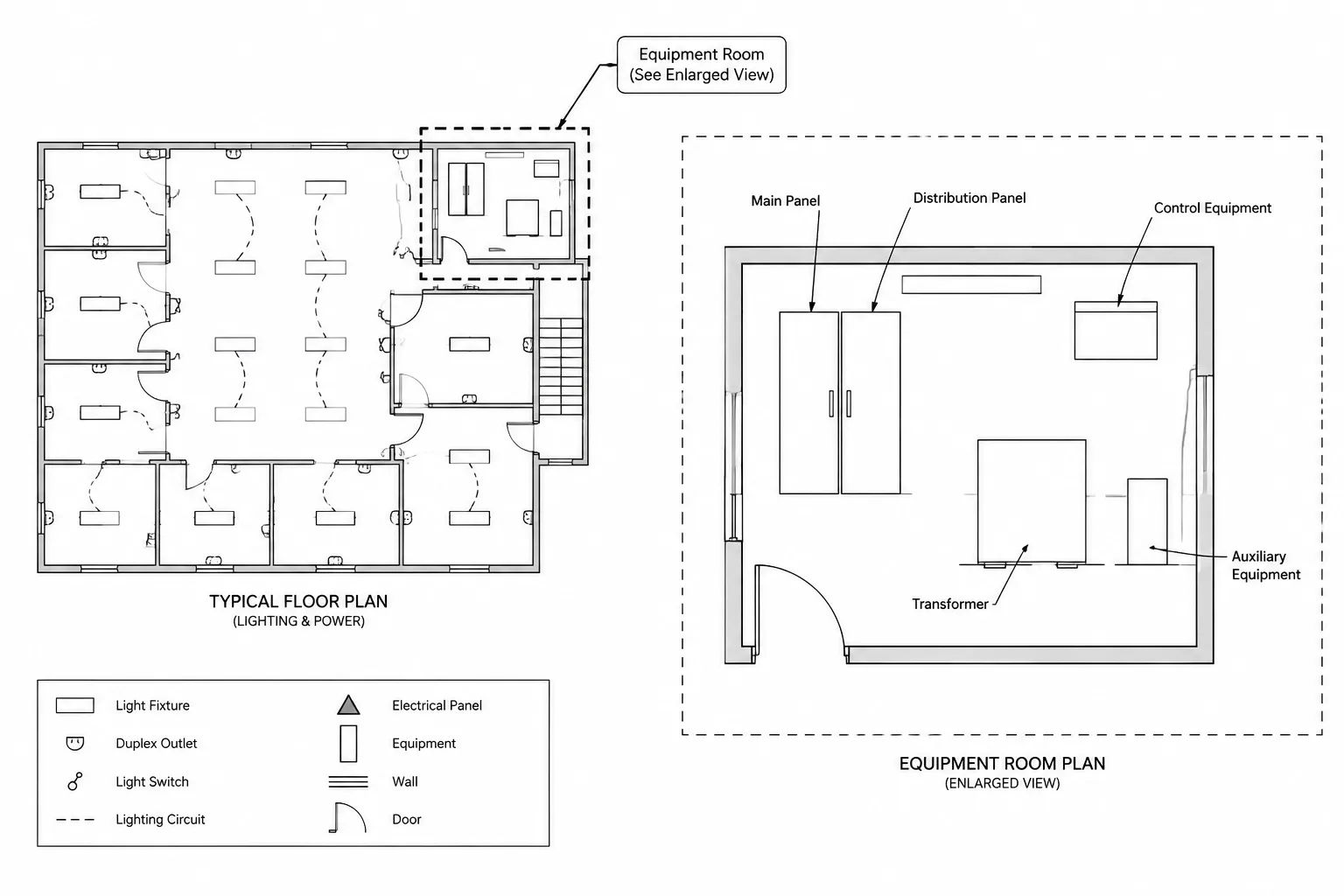
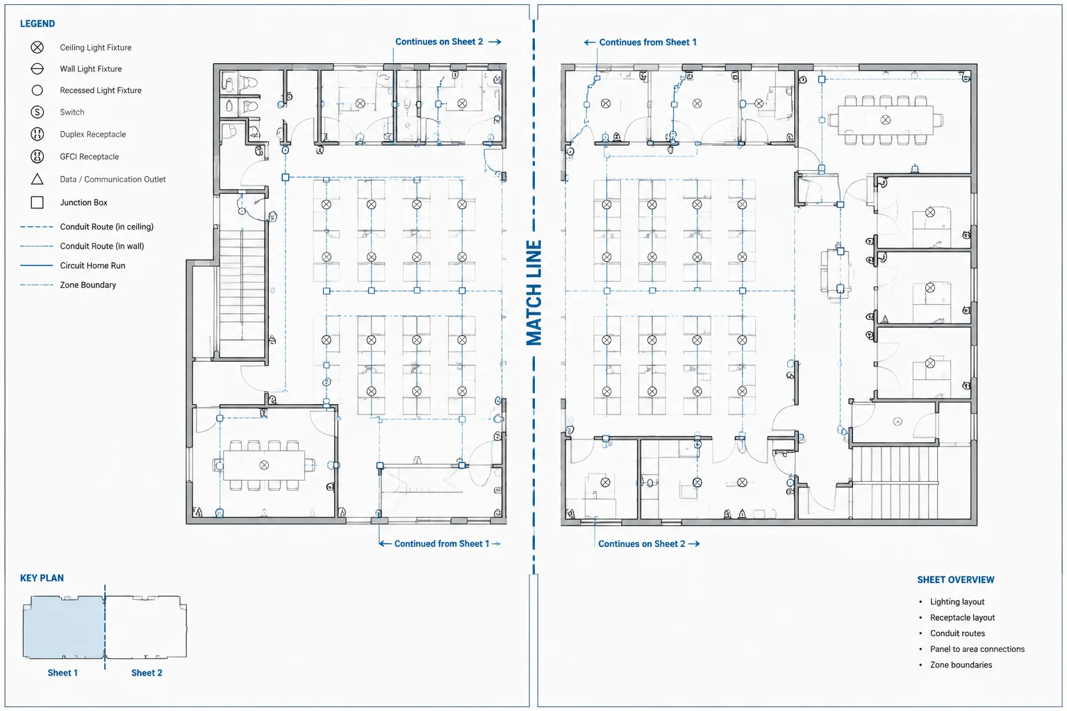
Symbols should also be coordinated with related documentation such as the electrical legend, single-line diagram, panel and distribution drawings, equipment layouts, lighting plans, and power plans. These drawing types provide context that the isolated CAD geometry does not contain.

Important Distinction: CAD Blocks and Intelligent Components
A DWG symbol may consist of standard CAD geometry rather than a data-rich electrical component. Do not assume that a downloaded block automatically includes catalog data, wire relationships, cross-references, attributes, or automated reporting behavior. Open the file, inspect the block definition, and adapt it to the requirements of the software workflow before adding it to a managed library.
Drawing Coordination and Verification
Generic electrical symbols can speed up drafting, but they do not replace project-specific engineering decisions. Verify symbol meaning, equipment identification, connections, notes, and legend entries against the applicable project requirements. Where multiple drafting conventions are involved, prioritize clarity and consistency throughout the complete drawing set.
Frequently Asked Questions
What types of AutoCAD electrical symbols are included?
The source description identifies circuit breakers, switches, contacts, relay coils, transformers, generators, starters, and meters.
Can these symbols be used in a single-line diagram?
Some symbol categories may be relevant to single-line diagrams, while others are more commonly associated with control schematics or panel documentation. Select only the graphics that match the purpose and convention of the drawing.

Are DWG symbols automatically intelligent electrical components?
Not necessarily. A DWG block can be ordinary CAD geometry without device data, automated cross-references, or electrical connectivity. Inspect the file structure and available attributes before integrating it into a software-specific workflow.
Why should the project legend be checked?
Electrical symbol appearance and interpretation can vary between organizations and drawing systems. A coordinated legend tells readers what each graphic represents within the specific document set.
What should be reviewed after importing the blocks?
Review layers, block names, insertion scale, linework, text styles, attributes, orientation, and plot appearance. Also check that imported definitions do not conflict with existing blocks in the destination drawing.
Can the symbols be placed directly into a final project drawing?
They should be reviewed and adapted first. Confirm that each symbol agrees with the project’s drafting conventions, equipment tags, notes, and documentation requirements.










Leave a Reply
You must be logged in to post a comment.