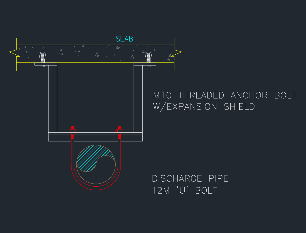
This pipe hanger through slab AutoCAD drawing provides a reusable reference for documenting a supported piping route at a concrete floor penetration. It can help drafters coordinate the relationship between the pipe, support components, slab opening, and surrounding construction within an MEP detail set.
Before incorporating the block into construction documents, review its geometry, units, layers, line types, and annotation style. The detail should be adapted to the project rather than treated as a complete installation specification.
This DWG file features a detailed CAD block of a pipe hanger passing through a slab, ideal for architects, MEP engineers, and construction professionals. The drawing accurately represents the installation of a pipe hanger system within a concrete slab, ensuring proper support and alignment for piping networks in residential, commercial, or industrial projects. Easily customizable and fully compatible with AutoCAD and other leading CAD software, this high-quality block streamlines your drafting process and enhances project documentation. Download this pipe hanger through slab DWG to save time and improve design accuracy on your next build.
Please log in or register to download this file.
Understanding the Detail
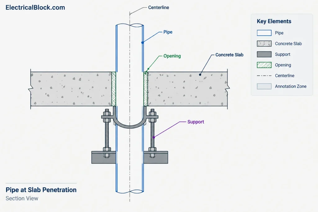
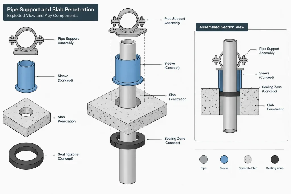
A through-slab piping detail may combine two related conditions: the penetration where the pipe crosses the slab and the support assembly that controls its position. The downloaded geometry should be inspected to determine exactly which components are represented. A support, sleeve, opening, seal, and fire-resistive treatment serve different functions and should not be assumed to be interchangeable.
Recommended CAD Review
- Confirm drawing units and scale: Compare the block with known project geometry before placing it in a detail or model-space view.
- Inspect layers: Move pipework, concrete, supports, hidden elements, centerlines, and annotations onto the office or project layer system as needed.
- Check block structure: Review insertion points, nested objects, attributes, and duplicate linework before adding the detail to a drawing library.
- Match graphic standards: Adjust lineweights, text styles, leaders, hatches, and plotting behavior to suit the destination sheet.
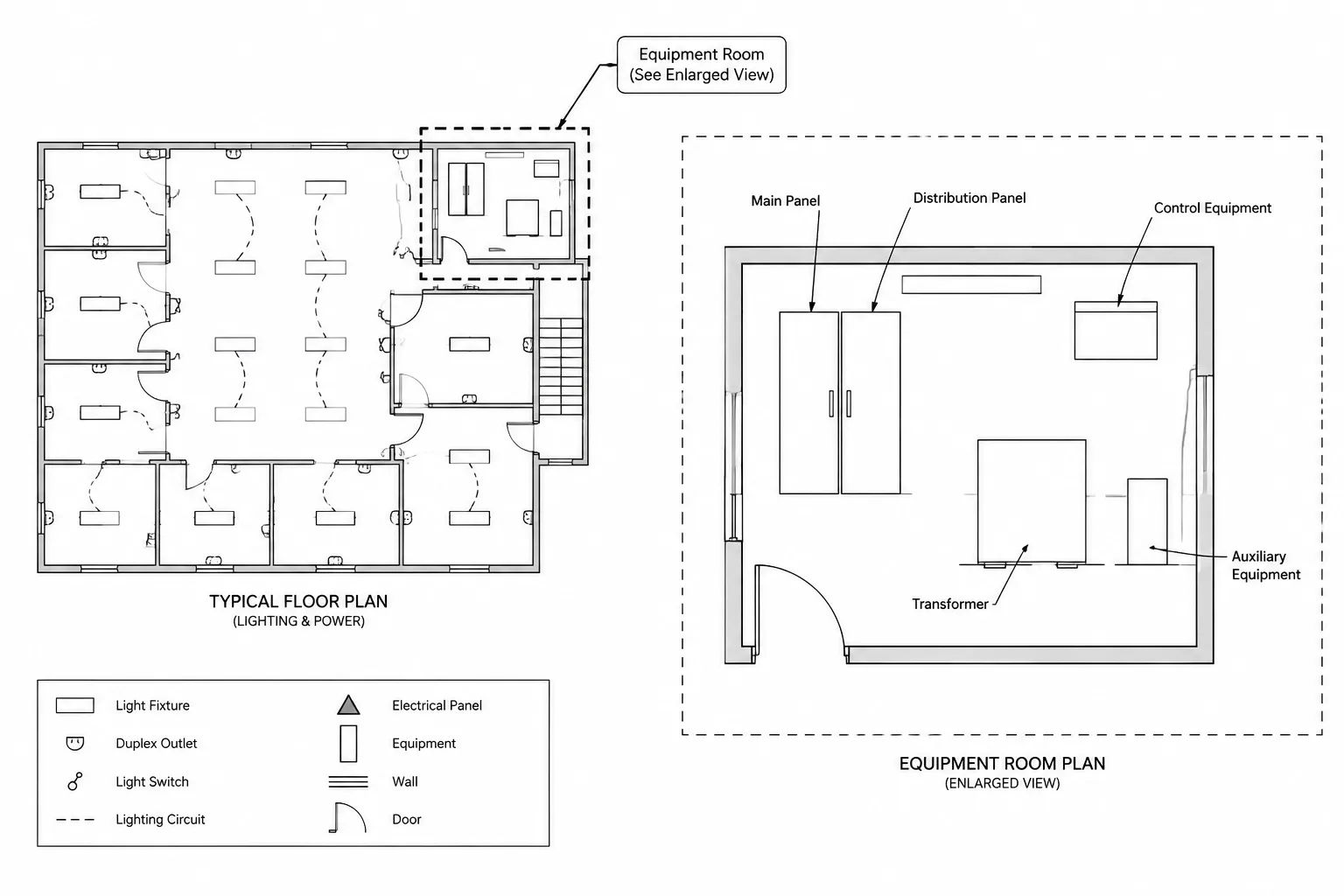
- Add project references: Identify the relevant plan location, detail callout, specification section, and coordination notes without overcrowding the view.
Coordination Considerations
Through-slab conditions commonly require coordination among piping, structural, architectural, fire-protection, and waterproofing documentation. The slab opening and support arrangement should be checked against the structural design, while any required sealing or fire-resistive system should be documented using approved project information.
Also check for conflicts with reinforcement zones, nearby services, ceiling space, access requirements, and equipment clearances. These considerations cannot be confirmed by a generic CAD block alone.
Related Drawing References
This detail can be reviewed alongside pipe support CAD blocks, slab penetration details, MEP coordination drawings, conduit support details, and construction drawing legends. Using consistent symbols and terminology across these references makes plan-to-detail navigation clearer for reviewers and installers.
Appropriate Use in Documentation
Use the block as a drafting starting point or educational reference. Final support selection, attachment method, penetration treatment, and component arrangement should be verified by the responsible design professionals and coordinated with applicable project requirements.
Frequently Asked Questions
What does a pipe hanger through slab detail show?
It generally illustrates the relationship between a piping route, its support arrangement, and a concrete slab penetration. The exact content depends on the objects included in the DWG, so each component should be identified during CAD review.
Is a pipe hanger the same as a pipe sleeve?
No. A hanger or support restrains and positions the piping, while a sleeve typically defines or protects the penetration path through construction. A detail may show both, but their functions should remain distinct in notes and specifications.

What should be checked before inserting the block?
Verify units, scale, insertion point, layers, line types, text styles, hatches, and block organization. Remove unnecessary objects and confirm that plotting matches the project CAD standard.
Can the drawing be used without modification?
It should be treated as a reference block rather than automatic approval for a project condition. Adapt the graphics and annotations, then obtain the required structural, MEP, fire-resistive, and architectural coordination.
Where should the detail be referenced?
It may be called out from a piping plan, coordination plan, section, enlarged area, or relevant detail sheet. The reference method should follow the project drawing index and office documentation conventions.










Leave a Reply
You must be logged in to post a comment.